


Siemens 7SR210 Argus, 7SR220 Argus Manual
Answers for energy
Reyrolle
Protection
Devices
7SR210 & 7SR220 Argus
Overcurrent Protection Relay
Siemens Protection Devices Limited 2
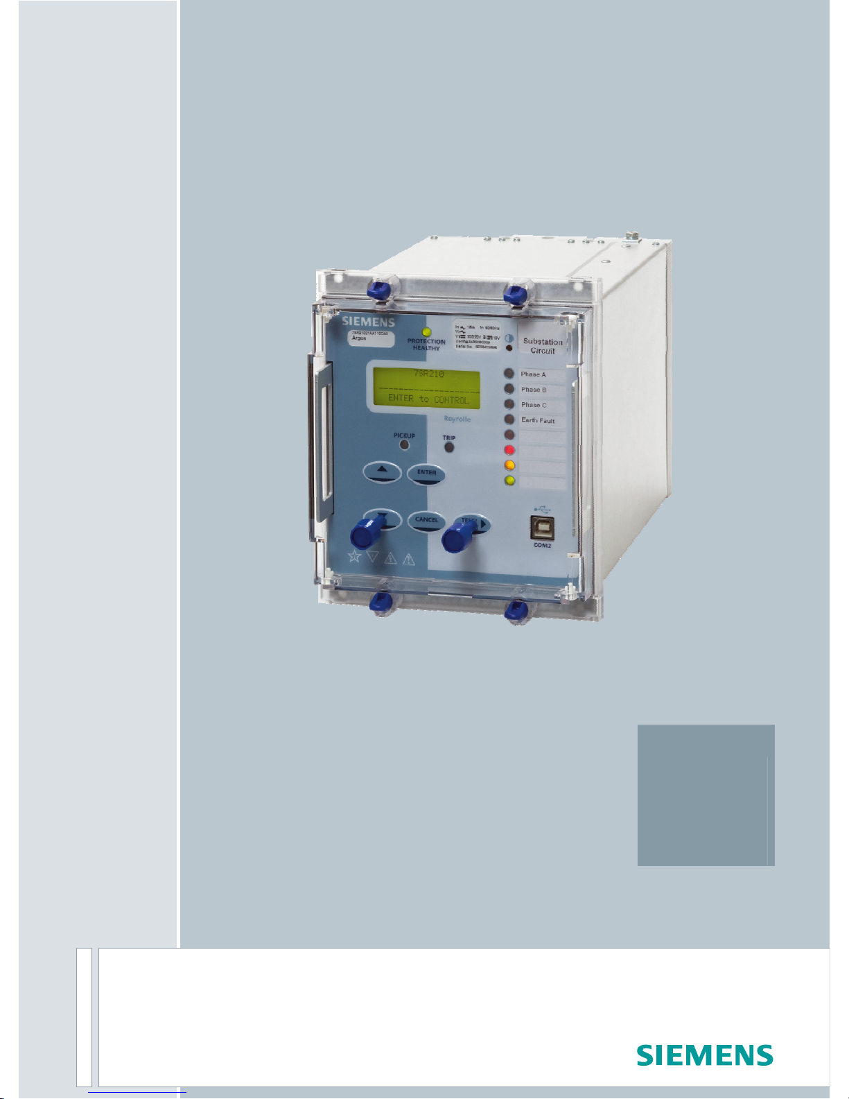
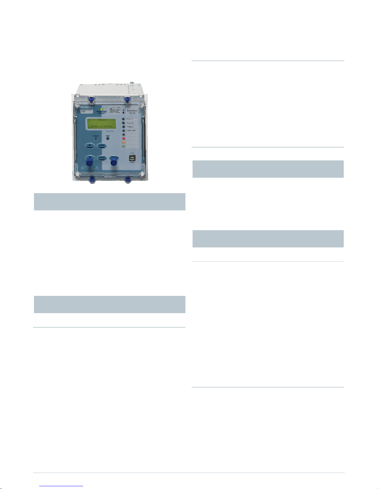
7SR210 7SR220 Argus
Overcurrent Protection Relay
The 7SR210n and 7SR220n are a new generation of nondirectional and directional overcurrent protection relays,
built on years of numeric relay protection experience with
the Argus family of products.
Housed in 4U high, size E6 or E8 cases, these relays provide
protection, control, monitoring, instrumentation and metering with integrated input and output logic, data logging &
fault reports. Communication access to relay functionality is
via a front USB port for local PC connection or rear electrical
RS485 port for remote connection. Additional rear port options are available.
Standard Functionality
37 Undercurrent
46BC Broken Conductor / Load Unbalance
46NPS Negative Phase Sequence Overcurrent
49 Thermal Overload
50 Instantaneous Overcurrent
50G/N Instantaneous Earth Fault
50BF Circuit Breaker Fail
51 Time Delayed Overcurrent
51G/N Time Delayed Measured Earth Fault /SEF
64H High Impedance REF
74TC Trip Circuit Supervision
81HBL2 2nd Harmonic Block/Inrush Restraint
51c Cold Load Pickup
8 Settings Groups
Password Protection – 2 levels
User Programmable Logic
Self Monitoring
Additional Functionality 7SR220n Directional Relay
27/59 Under/Over Voltage
47 Negative Phase Sequence (NPS) voltage
51V Voltage Dependent Overcurrent
59N Neutral Voltage Displacement
60CTS CT Supervision
60VTS VT Supervision
67/50 Bi-Directional Instantaneous Overcurrent
67/50G/N Bi-Directional Instantaneous Earth Fault
67/51 Bi-Directional Time Delayed Overcurrent
67/51G/N Bi-Directional Time Delayed Earth Fault
81 Under/Over Frequency
Optional Functionality
79 Auto Reclose
20 character x 4 line backlit LCD
Menu navigation keys
3 fixed LEDs
8 or 16 Programmable Tri-colour LEDs (Option)
6 Programmable Function Keys each with Tri-colour LED
(Option)
Standard Monitoring Functionality
Primary current phases and earth
Secondary current phases and earth
Positive Phase Sequence (PPS) Current
Negative Phase Sequence (NPS) Current
Zero Phase Sequence (ZPS) Current
Binary Input/Output status
Trip circuit healthy/failure
Time and date
Starters
Fault records
Event records
Frequency
Waveform records
Circuit breaker trip counters
I
2
t summation for contact wear
Demand metering
Additional Monitoring Functionality 7SR220n Directional
Relay
Direction
Primary line and phase voltages
Secondary voltages
Apparent power and power factor
Real and reactive power
W Hr forward and reverse
VAr Hr forward and reverse
Historical demand record
Positive phase sequence (PPS) Voltage
Negative phase sequence (NPS) Voltage
Zero phase sequence (ZPS) Voltage
Monitoring Functions
User Interface
Description
Function Overview

Standard Communications Ports
Communication access to relay functionality is via a front
USB port for local PC connection or rear electrical RS485 port
for remote connection
Optional Communications Ports
2 Rear ST fibre optic ports (2 x Tx/Rx) + IRIG-B port
1 Rear RS485 + IRIG-B port
1 Rear RS232 + IRIG-B port
Protocols
IEC60870-5-103, Modbus RTU and optional DNP 3.0
protocols – User selectable with programmable data points
Data
Event records
Fault records
Waveform records
Measurands
Commands
Time synchronism
Viewing and changing settings
With reference to figure 7 and figure 8 ‘Function Diagrams’.
37 Undercurrent
Each element has settings for pickup level and Definite Time
Lag (DTL) delays. Operates if current falls below setting for
duration of delay.
46BC Phase Unbalance/Broken Conductor
Element has settings for pickup level and DTL delay. With the
circuit breaker closed, if one or two of the line currents fall
below setting this could be due to a broken conductor.
6NPS Negative Phase Sequence Overcurrent
Two elements, one DTL and one IDMT, with user settings for
pickup level and delays, will operate if NPS Current exceeds
setting and delay. NPS Current elements can be used to detect unbalances on the system or remote earth faults when a
delta-star transformer is in circuit.
49 Thermal Overload
The thermal algorithm calculates the thermal states from the
measured currents and can be applied to lines, cables and
transformers. Outputs are available for thermal overload and
thermal capacity.
50/51 Phase Fault
Data Communications
50 INST/DTL and 51 IDMTL/DTL elements provide overcurrent
protection, each with independent settings for pickup current, time-multiplier (51) and time-delays. User can select
IEC or ANSI Time Current Characteristics. The IDMT stage has
a user programmable reset characteristic, either DTL or
shaped current/time reset characteristic, to improve grading
with electromechanical protection.
50G/51G/50N/51N Earth Fault/Sensitive Earth Fault
Two earth fault measurement modes are available. One
mode directly measures the earth current from an independent CT, or the residual connection of the 3 line CTs. This
input can be set to be either earth fault or sensitive earth
fault (50G/51G). The second mode derives the earth current
internally from the 3 phase CTs (50N/51N). 50 INST/DTL and
51 IDMTL/DTL elements provide overcurrent protection, each
with independent settings for pickup current, time-multiplier
(51) and time-delays. User can select IEC or ANSI Time Current Characteristics. The IDMT stage has a user programmable reset characteristic either DTL or shaped current/time
reset characteristic to improve grading with electromechanical protection.
50BF Circuit Breaker Fail
The circuit breaker fail function may be triggered from an
internal trip signal or from a binary input. Line currents are
monitored following a trip signal and an output is issued if
any current is still detected after a specified time interval.
This can be used to re-trip the CB or to back-trip an upstream
CB. A second back-trip time delay is available to enable another stage to be utilized if required.
Description of Functionality
64H Restricted Earth Fault - scheme
Standard Functionality
The measured earth fault input may be used in a 64H high
impedance restricted earth fault scheme.
Required external series stabilising resistor and non-linear
shunt resistor can be supplied.
74TC Trip Circuit Supervision
The trip circuit(s) can be monitored via binary inputs connected in H4/H5/H6 or H7 schemes. Trip circuit failure raises
an HMI alarm and output(s).
81HBL2 Harmonic Block / Inrush Restraint
Where second harmonic current is detected (i.e. during
transformer energisation) user selectable elements can be
blocked.
51c Cold Load
If a circuit breaker is closed onto a ‘cold’ load, i.e. one that
has not been powered for a prolonged period, this can impose a higher than normal load-current demand on the system which could exceed normal settings. These conditions
can exist for an extended period and must not be interpreted
as a fault. To allow optimum setting levels to be applied for
normal operation, the cold load pickup feature will apply
alternative settings for a limited period. The feature resets
when either the circuit breaker has been closed for a settable
period, or if the current has reduced beneath a set level for a
user set period.
Siemens Protection Devices Limited 3
Programmable User Logic
The user can map Binary Inputs and Protection operated
outputs to Function Inhibits, Logic Inputs, LEDs and/or Binary
Outputs.
The user can also enter up to 16 equations defining scheme
logic using standard functions e.g. Timers, AND/OR gates,
Inverters and Counters.
Each Protection element output can be used for Alarm &
Indication and/or tripping.
Circuit Breaker Maintenance
Two circuit breaker operations counters are provided. The
Maintenance Counters record the overall number of operations and the Delta Counter the number of operations since
the last reset.
An I
2
t summation Counter provides a measure of the contact
wear indicating the total energy interrupted by the circuit
breaker contacts.
Each counter has a user set target operations count which,
when reached, can be mapped to raise Alarms/ Binary Outputs.
These counters assist with maintenance scheduling
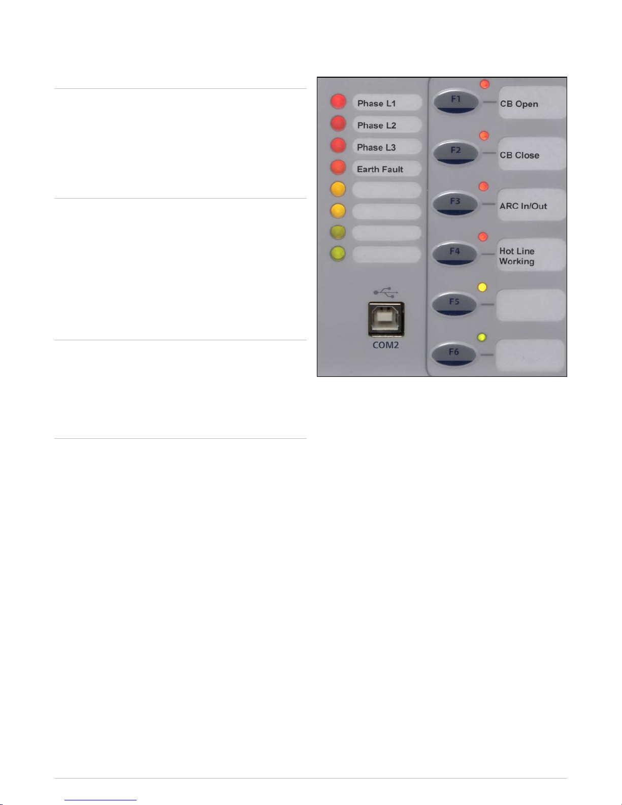
Function LED’s
Eight or sixteen user programmable tri-colour LED’s are
provided eliminating the need for expensive panel mounted
pilot lights and associated wiring. Each LED can be user set
to red, green or yellow allowing for clear indication of the
associated function’s state. A slip-in label pocket along-side
enables the user to insert customised notation. A printer
compatible template is available.
Function Keys
Six user programmable function keys are available for
implementing User logic and scheme control functionality,
eliminating the need for expensive panel mounted control
switches and associated wiring. Each function key has an
associated user programmable tri-color LED (red, green,
yellow) allowing for clear indication of the associated
function’s state. A slip-in label pocket along-side enables the
user to insert his own notation for the function Key LED
Identification.
Each Function Key can be mapped directly to any of the
built-in Command functions or to the User Logic equations.
Fig 1. Tri-colour LED’s and function keys
Siemens Protection Devices Limited 4

27/59 Under/Over Voltage
Each element has settings for pickup level, drop-off level and
Definite Time Lag (DTL) delays. Operates if voltage ‘exceeds’
setting for duration of delay. Can be applied in load
shedding schemes.
47 Negative Phase Sequence Overvoltage
Each element has settings for pickup level and Definite Time
Lag (DTL) delays. Operates if NPS Voltage exceeds setting for
duration of delay.
59N Neutral Overvoltage
Two elements, one DTL and one IDMTL, have user settings
for pickup level and delays. These will operate if the Neutral
voltage exceeds the setting for duration of delay. Neutral
overvoltage can be used to detect earth faults in high
impedance earthed or isolated systems.
60CTS CT Supervision
The CT Supervision considers the presence of negative phase
sequence current, without an equivalent level of negative
phase sequence voltage, for a user set time as a CT failure.
Element has user operate and delay settings.
60VTS VT Supervision
The VT Supervision uses a combination of negative phase
sequence voltage and negative phase sequence current to
detect a VT fuse failure. This condition may be alarmed or
used to inhibit voltage dependent functions. Element has
user operate and delay settings.
67/67N Directional Control
Phase fault, Earth fault and Sensitive Earth fault elements
can be directionalised. Each element can be user set to Forward, Reverse, or Non-directional.
Directional Phase fault elements are polarised from quadrature voltage.
Earth fault elements can be user set to be polarised from
residual voltage or negative phase sequence voltage.
81 Under/Overfrequency
Each element has settings for pickup level, drop-off level and
Definite Time Lag (DTL) delays. Operates if frequency exceeds setting for duration of delay. Typically applied in load
shedding schemes.
79 Auto-Reclose
This function provides independent Phase fault and Earth
Fault/Sensitive Earth fault sequences of up to 5 Trips i.e. 4
Reclose attempts before Lockout. Auto-Reclose sequence can
be user set to be initiated from internal protection operation
or via Binary Input from an external Protection. The user can
set each trip in the sequence to be either instantaneous
(Fast) or delayed. Independent times can be set by the user
for Reclose (Dead) time and Reclaim time.
Sequence of event records
Up to 5000 events are stored and time tagged to 1ms
resolution.
Fault Records
The last 10 fault records are displayed on the relay fascia and
are also available through the communication interface,
with time and date of trip, measured quantities and type of
fault.
Waveform recorder
The waveform recorder stores analogue data for all poles
and the states of protection functions, binary inputs, LEDs
and binary outputs with user settable pre & post trigger
data. A record can be triggered from protection function,
binary input or via data communications. Waveform storage
is selectable from either 10 records of 1 second, 5 records of
2 seconds, 2 records of 5 seconds or 1 record of 10 seconds
duration.
Demand Monitoring
A rolling record of demand over the last 24h is stored. The
demand is averaged over a user selectable period of time. A
rolling record of such demand averages is stored and
provides the demand history. A typical application is to
record 15min averages for the last 7 days.
Real Time Clock
The time and date can be set and are maintained while the
relay is de-energised by a back up storage capacitor. The
time can be synchronized from a binary input pulse or the
data communication channel.
Data Log
The average values of voltages, current and real & reactive
power are recorded at a user selectable interval and stored
to provide data in the form of a Data Log which can be
downloaded for further analysis. A typical application is to
record 15 minute intervals over the last 7 days.
Additional Functionality Data Acquisition -
Via Communication Interface
Optional Functionality
Siemens Protection Devices Limited 5
 Loading...