


Siemens 7MF4333, 7MF4033, 7MF4233, 7MF4433, 7MF4533 User Manual
...
Siemens Industry, Inc.
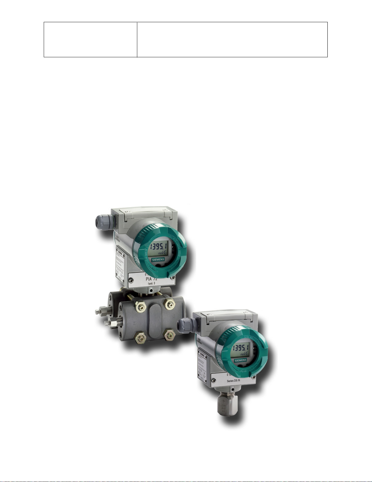
SITRANS P, Series DSIII Transmitters
Pressure, Differential Pressure,
Flanged Level, and Absolute Pressure
USER'S MANUAL
for
Model 7MF4*33-
UMSITRPDS3-1
Rev 10
November 2010
Supersedes Rev 9

IMPORTANT
MODEL 275 HART COMMUNICATOR AND
MODEL 375 FIELD COMMUNICATOR
Many procedures, screens, and wiring diagrams shown in this manual feature the Model 275 HART
Communicator.
The Model 375 Field Communicator is also available. Procedures and screens are similar to those for the
Model 275, however, there are significant differences and an online Configuration Map for use with the
Model 375 is provided at the back of this manual.
Transmitter model and firmware version can affect the displays, display options, and Configuration Maps.
Whether using the Model 275 or the Model 375, be sure to read the manual supplied by the manufacturer
before installing or using the device. Refer to the communicator nameplate for hazardous area
certifications and approvals and other important information.
APPLICATION AND MODEL QUICK LOCATOR
The following table provides an overview of measurement categories and available models. For details
pertaining to a particular model, see the appropriate section for a dimension drawing, the model
designation table and specifications in Section 9 Model Designations and Specifications. To quickly
locate other information, refer to the Table of Contents.
Measurement Models
Section
See
Dimensions
Model
Designation
Specifications
Absolute or Gauge
Pressure
Differential
Pressure
Level (Flange)
7MF4033
7MF4233
7MF4333
7MF4433
7MF4533
7MF4633
7MF4812
9.1
9.2
9.3
9.4 Figure 9-3 or 9-4
9.5 Figure 9-5 Table 9-10 Table 9-11
Figure 9-1
Figure 9-2
Figure 9-3
Table 9-1
Table 9-3
Table 9-5
Table 9-7
Table 9-8
Table 9-2
Table 9-4
Table 9-6
Table 9-9

UMSITRPDS3-1 Contents
TABLE OF CONTENTS
Section and Title Page
Conventions, Symbols, and General Information.................................................................viii
Conventions and Symbols ...................................................................................................viii
Scope ..................................................................................................................................viii
Warranty ............................................................................................................................... ix
Qualified Persons ................................................................................................................. ix
General Warnings and Cautions........................................................................................... ix
1.0 INTRODUCTION....................................................................................................1-1
1.1 CONTENTS......................................................................................................................1-1
1.2 PRODUCT DESCRIPTION ..............................................................................................1-2
1.3 RATING, APPROVAL, AND TAG PLATES......................................................................1-9
1.4 CONFIGURATION ...........................................................................................................1-9
1.5 CUSTOMER/PRODUCT SUPPORT..............................................................................1-10
2.0 MODEL 275 UNIVERSAL HART COMMUNICATOR............................................2-1
2.1 INTRODUCTION..............................................................................................................2-1
2.2 COMMUNICATOR CONNECTIONS................................................................................2-1
2.3 CONTROLS OVERVIEW .................................................................................................2-4
2.3.1 Liquid Crystal Display ................................................................................................2-4
2.3.2 Software-Defined Function Keys ...............................................................................2-4
2.3.3 Action Keys................................................................................................................2-6
2.3.4 Alphanumeric and Shift Keys.....................................................................................2-7
2.4 GETTING TO KNOW THE COMMUNICATOR ................................................................2-8
2.4.1 Display Icons .............................................................................................................2-8
2.4.2 Menu Structure ..........................................................................................................2-9
2.4.3 Reviewing Installed Devices......................................................................................2-9
2.5 MAIN MENU...................................................................................................................2-11
2.5.1 Offline Menu ............................................................................................................2-12
2.5.2 Online Menu ............................................................................................................2-18
2.5.3 Frequency Device Menu..........................................................................................2-21
2.5.4 Utility Menu..............................................................................................................2-21
2.6 USING THE QUICK ACCESS KEY................................................................................2-23
2.6.1 Adding Quick Access Key Options ..........................................................................2-24
2.6.2 Deleting Quick Access Key Options ........................................................................2-25
3.0 PRE-INSTALLATION TEST ..................................................................................3-1
3.1 PROCEDURE ..................................................................................................................3-1
3.1.1 Test Equipment..........................................................................................................3-2
3.2 ESTABLISHING COMMUNICATION ...............................................................................3-3
3.3 TESTING THE TRANSMITTER .......................................................................................3-3
3.4 REVIEWING CONFIGURATION DATA ...........................................................................3-4
3.5 CHECKING TRANSMITTER OUTPUT ............................................................................3-4
4.0 INSTALLATION.....................................................................................................4-1
4.1 EQUIPMENT DELIVERY AND HANDLING .....................................................................4-1
4.1.1 Receipt of Shipment ..................................................................................................4-1
4.1.2 Storage ......................................................................................................................4-1
4.2 ENVIRONMENTAL CONSIDERATIONS .........................................................................4-2
4.3 PRE-INSTALLATION CONSIDERATIONS AND CALCULATIONS .................................4-2
November 2010
i

Contents UMSITRPDS3-1
4.3.1 Mechanical ................................................................................................................4-2
4.3.2 Electrical ....................................................................................................................4-3
4.3.3 Impulse Piping for Absolute and Differential Models .................................................4-4
4.3.4 Transmitter Operating Mode and Network Type......................................................4-10
4.3.5 Power Supply Requirements ...................................................................................4-14
4.3.6 Determining Network (Loop) Length........................................................................4-17
4.3.7 Network Junctions ...................................................................................................4-19
4.3.8 Safety Barriers.........................................................................................................4-19
4.3.9 Connection of Miscellaneous Hardware ..................................................................4-20
4.3.10 Shielding and Grounding .......................................................................................4-21
4.4 MECHANICAL INSTALLATION .....................................................................................4-22
4.4.1 Pipe Mounting, Differential and Gauge Construction...............................................4-22
4.4.2 Direct Mounting to Process, Model 7MF4433 or 7MF4533 .....................................4-24
4.4.3 Flange Mounting, Model 7MF4633/7MF4812..........................................................4-25
4.5 MECHANICAL INSTALLATION, All Models...................................................................4-27
4.5.1 Enclosure Rotation ..................................................................................................4-27
4.5.2 Display Orientation ..................................................................................................4-28
4.5.3 Electrical Conduit and Cable Installation .................................................................4-29
4.6 ELECTRICAL INSTALLATION.......................................................................................4-31
4.7 HAZARDOUS AREA INSTALLATION............................................................................4-33
5.0 POST-INSTALLATION TEST................................................................................5-1
5.1 TEST EQUIPMENT..........................................................................................................5-1
5.2 INSTALLATION REVIEW.................................................................................................5-1
5.3 EQUIPMENT CONNECTION ...........................................................................................5-2
5.4 VERIFICATION ................................................................................................................5-3
5.4.1 Communication Test..................................................................................................5-3
5.4.2 Transmitter Selftest....................................................................................................5-3
5.4.3 Loop Test...................................................................................................................5-4
5.5 TRANSMITTER ZERO AND SHUTOFF VALVE MANIPULATION ..................................5-5
5.5.1 Absolute Pressure .....................................................................................................5-5
5.5.2 Differential Pressure and Flow...................................................................................5-8
5.5.3 Measuring Vapor .....................................................................................................5-11
6.0 ON-LINE CONFIGURATION AND OPERATION ..................................................6-1
6.1 LOCAL OPERATION AND DISPLAY...............................................................................6-1
6.1.1 Digital Display............................................................................................................6-1
6.1.2 Numeric Display.........................................................................................................6-2
6.1.3 Unit/Bargraph Display................................................................................................6-3
6.1.4 Error Message ...........................................................................................................6-3
6.1.5 Output Signal Range .................................................................................................6-3
6.1.6 Mode Display...........................................................................................................6-4
6.2 LOCAL OPERATION WITH THE MAGNETIC PUSHBUTTONS .....................................6-5
6.2.1 Cancel Pushbutton Disable and Write Protection......................................................6-7
6.2.2 Set/Adjust Zero and Full Scale ..................................................................................6-7
6.2.3 Electric Damping......................................................................................................6-10
6.2.4 Blind Setting of Zero and Full Scale ........................................................................6-10
6.2.5 Zero Adjustment (Position Correction).....................................................................6-12
6.2.6 Fixed Current Output ...............................................................................................6-13
6.2.7 Failure Current.........................................................................................................6-13
6.2.8 Pushbutton and Function Disable............................................................................6-14
6.2.9 Flow Measurement (Differential Pressure only).......................................................6-14
6.2.10 Select Measured Value to Display.........................................................................6-16
November 2010
ii

UMSITRPDS3-1 Contents
6.2.11 Select the Displayed Input Pressure Engineering Unit..........................................6-16
6.3 LOCAL OPERATION WITHOUT A DISPLAY OR WITH ACTIVATED KEYLOCK.........6-18
6.3.1 Set Zero and Full Scale ...........................................................................................6-18
6.4 REMOTE CONFIGURATION AND OPERATION BY HART..........................................6-20
6.4.1 Process Data ...........................................................................................................6-20
6.4.2 Setting Zero and Full Scale .....................................................................................6-21
6.4.3 Blind Setting of Zero and Full Scale ........................................................................6-21
6.4.4 Zero Adjustment for Position Correction..................................................................6-21
6.4.5 Electric Damping......................................................................................................6-22
6.4.6 Fast Measured Value Acquisition (fast response mode) .........................................6-22
6.4.7 Fixed Current Output ...............................................................................................6-23
6.4.8 Fault Current............................................................................................................6-23
6.4.9 Disabling the Transmitter Magnetic Pushbuttons and Write Protection...................6-24
6.4.10 Measured Value Display........................................................................................6-25
6.4.11 Select Pressure Engineering Units........................................................................6-25
6.4.12 Display/Bargraph ...................................................................................................6-25
6.4.13 Sensor Trim ...........................................................................................................6-26
6.4.14 D/A Trim.................................................................................................................6-28
6.4.15 Transmitter Current Adjustment.............................................................................6-28
6.4.16 Factory Calibration (Manufacturer Trims) ..............................................................6-29
6.4.17 Device Information.................................................................................................6-30
6.4.18 Flow Measurement (Differential Pressure) ............................................................6-30
6.4.19 Diagnostic Functions .............................................................................................6-30
6.4.20 Simulation..............................................................................................................6-33
6.4.21 Self Test and Master Reset ...................................................................................6-34
7.0 CALIBRATION AND MAINTENANCE ..................................................................7-1
7.1 CALIBRATION .................................................................................................................7-2
7.2 PREVENTIVE MAINTENANCE........................................................................................7-3
7.2.1 Transmitter Exterior Inspection..................................................................................7-3
7.2.2 Transmitter Exterior Cleaning ....................................................................................7-3
7.2.3 Transmitter Enclosure Interior Inspection..................................................................7-4
7.2.4 Transmitter Calibration ..............................................................................................7-4
7.2.5 Impulse Piping ...........................................................................................................7-4
7.3 TROUBLESHOOTING .....................................................................................................7-5
7.3.1 Analog Output............................................................................................................7-5
7.3.2 Digital Output (Communication).................................................................................7-8
7.4 ASSEMBLY REMOVAL AND REPLACEMENT ...............................................................7-9
7.4.1 Display Assembly ....................................................................................................7-11
7.4.2 Replacing the Electronics Module ...........................................................................7-12
7.4.3 Measuring Cell Assembly Removal and Replacement............................................7-13
7.4.4 Terminal Board Assembly Removal and Replacement ...........................................7-16
7.5 NON-FIELD-REPLACEABLE ITEMS .............................................................................7-16
7.6 TRANSMITTER REPLACEMENT ..................................................................................7-17
7.7 MAINTENANCE RECORDS ..........................................................................................7-18
7.8 RECOMMENDED SPARE AND REPLACEMENT PARTS ............................................7-18
7.9 COMPATIBILITY, Revision Numbers.............................................................................7-19
8.0 CIRCUIT DESCRIPTION .......................................................................................8-1
8.1 OVERALL OPERATION...................................................................................................8-2
8.2 PRESSURE......................................................................................................................8-2
8.3 DIFFERENTIAL PRESSURE AND FLOW .......................................................................8-3
8.4 FLANGED LEVEL ............................................................................................................8-3
November 2010
iii

Contents UMSITRPDS3-1
8.5 ABSOLUTE PRESSURE (DIFFERENTIAL CONSTRUCTION).......................................8-4
8.6 ABSOLUTE PRESSURE (GAUGE CONSTRUCTION) ...................................................8-4
8.7 COMMUNICATION FORMAT ..........................................................................................8-5
9.0 MODEL DESIGNATIONS AND SPECIFICATIONS ..............................................9-1
9.1 MODEL 7MF4033, GAGE PRESSURE ...........................................................................9-2
9.2 MODEL 7MF4233, ABSOLUTE PRESSURE...................................................................9-7
9.3 MODEL 7MF4333, ABSOLUTE PRESSURE.................................................................9-12
9.4 MODELS 7MF4433 AND 7MF4533, DIFFERENTIAL PRESSURE AND FLOW ...........9-17
9.5 MODELS 7MF4633 AND 7MF4812, LEVEL ..................................................................9-24
9.6 SERVICE PARTS, ALL MODELS ..................................................................................9-30
9.7 ACCESSORIES .............................................................................................................9-35
9.8 NETWORK TOPOLOGY ................................................................................................9-35
9.8.1 Two-Wire Cable.......................................................................................................9-35
9.9 HAZARDOUS AREA CLASSIFICATION........................................................................9-36
9.9.1 CSA Hazardous Locations Precautions...................................................................9-38
10.0 GLOSSARY.......................................................................................................10-1
11.0 APPENDIX A - ONLINE CONFIGURATION MAP.............................................11-1
12.0 APPENDIX B - HAZARDOUS AREA INSTALLATION.....................................12-1
13.0 APPENDIX C - ELEVATION AND SUPPRESSION CORRECTIONS...............13-1
13.1 HOW ADJUSTMENT IS MADE....................................................................................13-1
13.2 ELEVATION CALCULATION EXAMPLE .....................................................................13-2
13.3 SUPPRESSION CALCULATION EXAMPLE ...............................................................13-2
13.4 RECOMMENDED METHOD ........................................................................................13-3
Online Configuration Map (with Model 275 Communicator)
Online Configuration Map (with Model 375 Communicator)
LIST OF FIGURES
Figure and Title Page
1-1 Gauge Construction, Pressure and Absolute Pressure Models .........................................1-3
1-2 Differential Construction; Differential, Flow, and Absolute Models .....................................1-4
1-3 Differential Pressure and Flow Models with H03 Option ....................................................1-5
1-4 Flanged Liquid Level Models ..............................................................................................1-6
1-5 Traditional Application ........................................................................................................1-7
1-6 Digital Display and Field Terminals ....................................................................................1-8
2-1 Model 275 Universal HART Communicator........................................................................2-2
2-2 HART Communicator Connections to a Transmitter Loop .................................................2-3
2-3 HART Communicator Display Icons ...................................................................................2-8
2-4 Offline Menu Map .............................................................................................................2-12
2-5 SITRANS P Online Menu Map .........................................................................................2-19
2-6 Generic Online Menu Map................................................................................................2-20
3-1 Bench Test Connections.....................................................................................................3-1
3-2 Field Test Connections .......................................................................................................3-2
4-1 Differential Flow Measurement Piping for Gas and Liquid..................................................4-5
4-2 Differential Liquid Measurement Piping ..............................................................................4-6
4-3 Absolute or Gauge Pressure Measurement Piping ............................................................4-7
4-4 Steam Service, Below the Line Mounting ...........................................................................4-8
November 2010
iv

UMSITRPDS3-1 Contents
4-5 Open and Closed Tank Level Measurement, Flange Mounted Transmitters .....................4-9
4-6 Point-To-Point Network (Analog Mode) ............................................................................4-11
4-7 Procidia to Transmitter Connections (Analog Mode) ........................................................4-12
4-8 Model 353/354 to Transmitter Connections (Analog Mode) .............................................4-13
4-9 Multi-Drop Network (Digital Mode)....................................................................................4-15
4-10 Power Supply vs. Loop Resistance ................................................................................4-16
4-11 Pipe Mounting, Gauge Construction...............................................................................4-23
4-12 Pipe Mounting, Differential Construction ........................................................................4-23
4-13 Differential Construction, Position Options .....................................................................4-24
4-14 Enclosure Rotation Considerations ................................................................................4-27
4-15 Display Removal and Repositioning ...............................................................................4-28
4-16 Conduit Drain and Explosion Proof Installations.............................................................4-29
4-17 Network Conductor Terminations ...................................................................................4-32
5-1 Equipment Connection for System Checkout .....................................................................5-2
5-2 Measuring Gases................................................................................................................5-6
5-3 Measuring Vapor and Liquid...............................................................................................5-7
5-4 Measuring Gases................................................................................................................5-9
5-5 Measuring Liquids.............................................................................................................5-10
5-6 Measuring Vapor ..............................................................................................................5-11
6-1 Digital Display .....................................................................................................................6-1
6-2 Switch Point of the Square Root Characteristic................................................................6-15
6-3 Displayable Engineering Units..........................................................................................6-17
6-4 Sensor Trim ......................................................................................................................6-27
6-5 Pressure Min/Max Pointer Example .................................................................................6-32
6-6 Saturation Monitoring Examples.......................................................................................6-33
6-7 Simulation Circuit Diagram ...............................................................................................6-34
7-1 Transmitter Exploded View.................................................................................................7-9
7-2 Display Assembly Installed and Partially Removed..........................................................7-11
7-3 Electronics Module Removal and Installation ...................................................................7-12
7-4 Measuring Cell Alignment and Insertion Depth ................................................................7-15
8-1 Transmitter Block Diagram .................................................................................................8-1
8-2 Pressure Measuring Cell ....................................................................................................8-2
8-3 Differential Pressure and Flow Measuring Cell...................................................................8-3
8-4 Flanged Level Measuring Cell ............................................................................................8-4
8-5 Absolute Pressure Measuring Cell, Differential Construction .............................................8-4
8-6 Absolute Pressure Measuring Cell, Gauge Construction ...................................................8-5
9-1 Model 7MF4033, Dimensions .............................................................................................9-2
9-2 Model 7MF4233, Dimensions .............................................................................................9-7
9-3 Models 7MF4333, 7MF4433 and 7MF4533, Dimensions.................................................9-12
9-4 Models 7MF4433 and 7MF4533, Dimensions, With H03 Option......................................9-17
9-5 Models 7MF4633 and 7MF4812, Dimensions ..................................................................9-24
11-1 Online Configuration Map, Part 1 of 2 ............................................................................11-2
11-2 Online Configuration Map, Part 2 of 2 ............................................................................11-3
12-1 Control Drawing ..............................................................................................................12-2
12-2 Control Drawing ..............................................................................................................12-3
12-3 Control Drawing ..............................................................................................................12-4
13-1 Elevation and Suppression Examples ............................................................................13-1
November 2010
v

Contents UMSITRPDS3-1
LIST OF TABLES
Table and Title Page
1-1 Measurements, Models and Figure References.................................................................1-2
2-1 Function Keys with Their Labels and Actions Performed ...................................................2-5
2-2 Communicator Firmware Device Descriptions, Rev. F2.2 ................................................2-10
2-3 Offline Menu Map Continued, “Edit individually” Options1................................................2-12
4-1 Operating Mode and Network...........................................................................................4-10
4-2 Flange And Extension Dimensions...................................................................................4-26
6-1 Operating Mode and Status Arrows....................................................................................6-2
6-2 Parameters Accessible Using the Magnetic Pushbuttons ..................................................6-6
6-3 Pushbutton and Function Disable Options .......................................................................6-14
6-4 Pushbutton and Function Disable Options .......................................................................6-24
9-1 Model 7MF4033, Model Designation ..................................................................................9-3
9-2 Model 7MF4033, Specifications..........................................................................................9-5
9-3 Model 7MF4233, Model Designation ..................................................................................9-8
9-4 Model 7MF4233, Specifications........................................................................................9-10
9-5 Model 7MF4333, Model Designation ................................................................................9-13
9-6 Model 7MF4333, Specifications........................................................................................9-15
9-7 Model 7MF4433, Model Designation ................................................................................9-18
9-8 Model 7MF4533, Model Designation ................................................................................9-20
9-9 Models 7MF4433 and 7MF4533, Specifications...............................................................9-22
9-10 Models 7MF4633 and 7MF4812, Model Designation .....................................................9-25
9-11 Models 7MF4633 and 7MF4812, Specifications.............................................................9-28
9-12 Measuring Cells for Pressure, Service Parts ..................................................................9-30
9-13 Measuring Cells for Absolute Pressure, Gauge Construction, Service Parts .................9-31
9-14 Measuring Cells for Absolute Pressure, Differential Const., Service Parts ....................9-31
9-15 Measuring Cells for Pressure and Flow, Differential Const., Service Parts....................9-32
9-16 Measuring Cells for Differential Pressure and Flow, Service Parts ................................9-33
9-17 Measuring Cells for Filling Level, Service Parts .............................................................9-34
9-18 Electronics and Connecting Boards, Service Parts ........................................................9-34
9-19 Accessories ....................................................................................................................9-35
9-20 Certificate and Approvals, All Models .............................................................................9-37
November 2010
vi

UMSITRPDS3-1 Contents
Changes for Revision 10, November 2010
Significant changes for Rev. 10 are listed below.
Section Revision
Cover Change publication revision number and date.
Conventions, Symbols and General
Information
Update section text; include Warranty subsection and add
“operating time” warranty details.
1.5 Customer/Product Support Update section text and contact information table.
6.2 On-Line Operation Update Table 6-2, Mode 11.
Throughout publication Change Siemens Energy & Automation, Inc. to Siemens
Industry, Inc.
Warranty Remove from publication; see Conventions, Symbols and
General Information above.
SITRANS P, Series DS III, and Procidia are trademarks of Siemens Industry, Inc. Viton and Kalrez
DuPont Performance Elastomers. Teflon
registered trademark of Haynes International. Monel is a registered trademark of Special Metals Corporation. HART is a
registered trademark of the HART Communication Foundation. All product designations may be trademarks or product names of
Siemens Industry, Inc. or other supplier companies whose use by third parties for their own purposes could violate the rights of
the owners.
Siemens Industry, Inc. assumes no liability for errors or omissions in this document or for the application and use of information
included in this document. The information herein is subject to change without notice.
Procedures in this document have been reviewed for compliance with applicable approval agency requirements and are
considered sound practice. Neither Siemens Industry, Inc. nor these agencies are responsible for product uses not included in the
approval certification(s) or for repairs or modifications made by the user.
is a registered trademark of E. I. du Pont de Nemours and Company. Hastelloy is a
are registered trademarks of
!
November 2010
vii
Contents UMSITRPDS3-1
Conventions, Symbols, and General Information
Conventions and Symbols
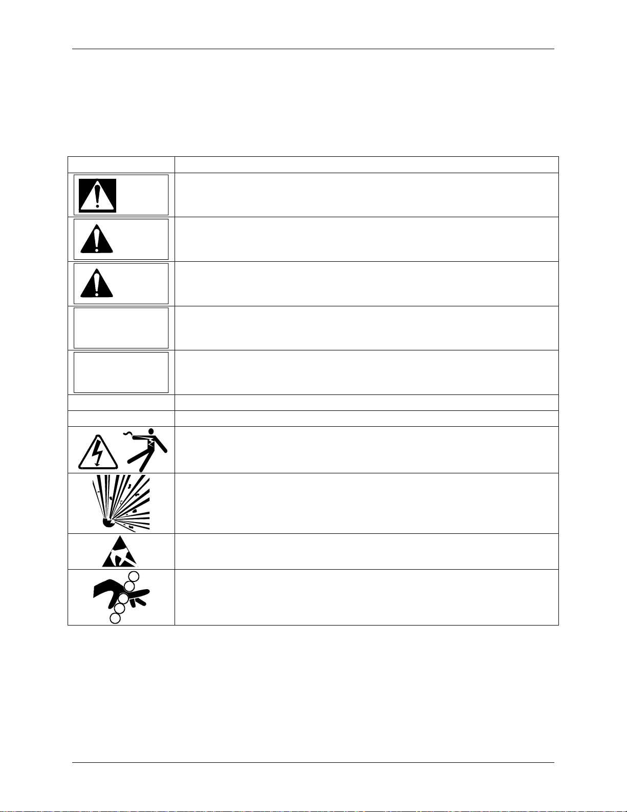
The following symbols may be used in this manual and may appear on the equipment. The reader should
be familiar with the symbols and their meanings. Symbols are provided to quickly alert the reader to
safety related text.
Symbol Meaning
Indicates an immediate hazardous situation which, if not avoided, will result in
DANGER
death or serious injury.
Indicates a potentially hazardous situation which, if not avoided, could result in
WARNING
death or serious injury.
Indicates a potentially hazardous situation which, if not avoided, may result in
CAUTION
minor or moderate injury.
Indicates a potentially hazardous situation which, if not avoided, may result in
CAUTION
property damage.
Indicates a potential situation which, if not avoided, may result in an undesirable
NOTICE
result or state.
IMPORTANT
Note
Identifies an action that should be taken to avoid an undesirable result or state.
Identifies supplemental information that should be read before proceeding.
Electrical shock hazard – Either symbol indicates the presence of an electrical
shock hazard. The associated text states the nature of the hazard, what can happen
as a result of the hazard, and how to avoid the hazard..
Explosion hazard – Symbol indicates that the danger of an explosion hazard
exists. The associated text states the nature of the hazard, what can happen as a
result of the hazard, and how to avoid the hazard.
Electrostatic discharge – The presence of this symbol indicates that electrostatic
discharge can damage the electronic assembly.
Pinch hazard – Symbol indicates that a pinch hazard exists if correct procedures
are not followed.
Part numbers are for items ordered from the Process Instrumentation & Analytics Business Unit of
Siemens Industry, Inc., except as noted.
Scope
This manual does not purport to cover all details or variations in equipment or to provide for every
possible contingency to be met in connection with installation, operation, or maintenance. Should further
information be desired or should particular problems arise which are not covered sufficiently for the
purchaser’s purposes, the matter should be referred to a support group listed in the Customer/Product
November 2010
viii

UMSITRPDS3-1 Contents
Support section of this manual or to the local Siemens sales office. The contents of this manual shall not
become part of or modify any prior or existing agreement, commitment or relationship.
Warranty
The SITRANS P DSIII transmitter warranty is based on actual operating hours, as shown in the Operating
Hours Register. The transmitter is warranted for 60 months of operation in two successive steps:
1. A 36-month 100% warranty from date of initial operation.
2. A 24-month pro-rated warranty which decreases linearly from 100% at 36 months to 0% at 60 months
of powered operation.
If Siemens cannot determine transmitter operating hours, the warranty shall commence on the date of
shipment from Siemens. All other provisions of the Siemens standard warranty remain as stated in the
sales contract.
Should the transmitter require repair during the pro-rated warranty period, the charge will be pro-rated
based on prevailing repair rates for parts and labor.
Qualified Persons
The described equipment should be installed, configured, operated, and serviced only by qualified
persons thoroughly familiar with this manual. A copy of this manual accompanies the equipment. The
current version of the manual, in Portable Document Format (PDF), can be downloaded from the Siemens
Internet site; see the Customer/Product Support section of this manual for the address.
For the purpose of this manual and product labels, a qualified person is one who is familiar with the
installation, assembly, commissioning, and operation of the product, and who has the appropriate
qualifications for their activities such as:
• Training, instruction, or authorization to operate and maintain devices/systems according to the safety
standards for electrical circuits, high pressures, and corrosive, as well as, critical media.
• For devices with explosion protection: training, instruction or authorization to work on electrical
circuits for systems that could cause explosions.
• Training or instruction according to the safety standards in the care and use of suitable safety
equipment.
General Warnings and Cautions
WARNING
An explosion-proof device may be opened only after power is removed from the device.
An intrinsically safe device loses its license as soon as it is operated in a circuit that does not meet the
requirements of the examination certificate valid in your country.
The device may be operated with high pressure and corrosive media. Therefore, serious injury and/or
considerable material damage cannot be ruled out in the event of handling of the device.
The perfect and safe operation of the equipment is conditional upon proper transport, proper storage,
installation and assembly, as well as, on careful operation and commissioning.
November 2010
ix

Contents UMSITRPDS3-1
x
The equipment may be used only for the purposes specified in this manual.
CAUTION
Electrostatic discharge can damage or cause the failure of semiconductor devices such as
integrated circuits and transistors. The symbol at right appears on a circuit board or other
electronic assembly to indicate that special handling precautions are needed.
• A properly grounded conductive wrist or heel strap must be worn whenever an electronics module or
circuit board is handled or touched. Static control kits are available from most electrical and
electronic supply companies.
• Electronic assemblies must be stored in static protective bags when not installed in equipment.
!
November 2010

UMSITRPDS3-1 Introduction
1.0 INTRODUCTION
This user’s manual is for the Siemens SITRANS P Series DSIII Pressure Transmitters.
All information needed to bench test, install, configure, calibrate, and service a transmitter is included in
this user’s manual.
IMPORTANT
Save this user’s manual. It should be available to those installing, configuring,
operating, and servicing the described pressure transmitters.
1.1 CONTENTS
The user’s manual consists of a table of contents, ten sections, and three appendices. Following the table
of contents is a subsection that contains important information about the symbols that can appear in this
user’s manual and on the transmitter. The subsection also has statements about installing and servicing the
transmitter. A brief description of each major section and appendices follows.
Section 1, Introduction, describes each section in the manual and provides a brief description of the
SITRANS P Series DSIII Pressure Transmitter line. A product support section has telephone, fax, E-mail,
and Internet contact information.
Section 2, Model 275 Universal HART Communicator, describes use of the HART Communicator to test,
configure, and calibrate a transmitter.
Section 3, Pre-Installation Test, provides procedures to perform a bench test of the transmitter to ensure
proper operation of all transmitter functions. Start-up configuration is described here.
Section 4, Installation, furnishes specific information for mechanical and electrical installation of the
transmitter.
Section 5, Post-Installation Test, describes how to confirm that the transmitter has been installed correctly
- sometimes referred to as commissioning.
Section 6, On-Line Configuration and Operation, details local configuration using the magnetic
pushbuttons and remote configuration using the HART Communicator. Local operation and remote
operation of the transmitter are described.
Section 7, Calibration and Maintenance, provides references to calibration procedures for analog and
digital modes and to a zeroing procedure for mounting position. It also furnishes preventive maintenance,
troubleshooting, and assembly replacement procedures.
Section 8, Circuit Description, contains an assembly-level circuit description to support transmitter
servicing.
Section 9, Model Designations and Specifications, has tables that correlate rating plate model numbers to
transmitter physical configurations. This section also contains an accessory list and several service parts
lists. Detailed mechanical, functional, performance, and environmental specifications are provided, as are
dimension drawings of the transmitter. Hazardous area certifications are listed.
Section 10, Glossary, contains definitions of various transmitter-related terms.
November 2010
1-1

Introduction UMSITRPDS3-1
Appendix A, Online Configuration Map, is used to help navigate HART/transmitter menus during remote
configuration and operation of the transmitter.
Appendix B, Hazardous Area Installations, contains control drawings and other information needed for
installation in a hazardous area.
Appendix C, Elevation and Suppression Corrections, explains how to perform elevation and suppression
calculations necessary for certain liquid level gauging applications.
Warranty contains the product warranty statements and information concerning servicing of the product
during the warranty period.
1.2 PRODUCT DESCRIPTION
SITRANS P Series DSIII transmitters provide reliable, accurate, stable, and cost-effective measurement
of differential, absolute, and gauge pressure and liquid level.
The transmitter is a microcontroller-based, self-contained pressure-to-current transducer. A measuring
cell senses the applied process pressure and provides an analog output signal that is proportional to
applied pressure. An analog-to-digital converter produces a digital signal for the microcontroller. The
microcontroller modifies and corrects the signal for linearity and temperature, and a digital-to-analog
converter produces a 4-20 milliampere output signal for the loop.
The transmitter can be installed quickly and easily using one of the optional mounting brackets.
Illustrations showing mounting hardware and dimensions are provided in this manual. Measuring cell
construction determines a transmitter’s physical dimensions and mechanical installation. Note that a given
sensor construction can involve one or more measurement methods, as shown in Table 1-1.
TABLE 1-1 Measurements, Models and Figure References
Measurement Model And Measuring Cell Construction Refer To
Absolute or Gauge Pressure 7MF4033, Gauge Construction
7MF4233, Gauge Construction
Figures 1-1, 4-3, 4-4, 411, 4-13, 9-1, 9-2 and 93
7MF4333, Differential Construction
Differential Pressure 7MF4433, Differential Construction
7MF4533, Differential Construction
Liquid Level (Flange) 7MF4633, Flange Construction
7MF4812, Flange
Figures 1-2, 1-3, 4-1, 42, 4-12, 4-13, 9-3, and 94
Figures 1-4, 4-5, and 9-5
Figures 1-1 through 1-4 show the various transmitter models and constructions. They also show common
transmitter mounting methods. The mounting brackets shown are optional.
November 2010
1-2
UMSITRPDS3-1 Introduction
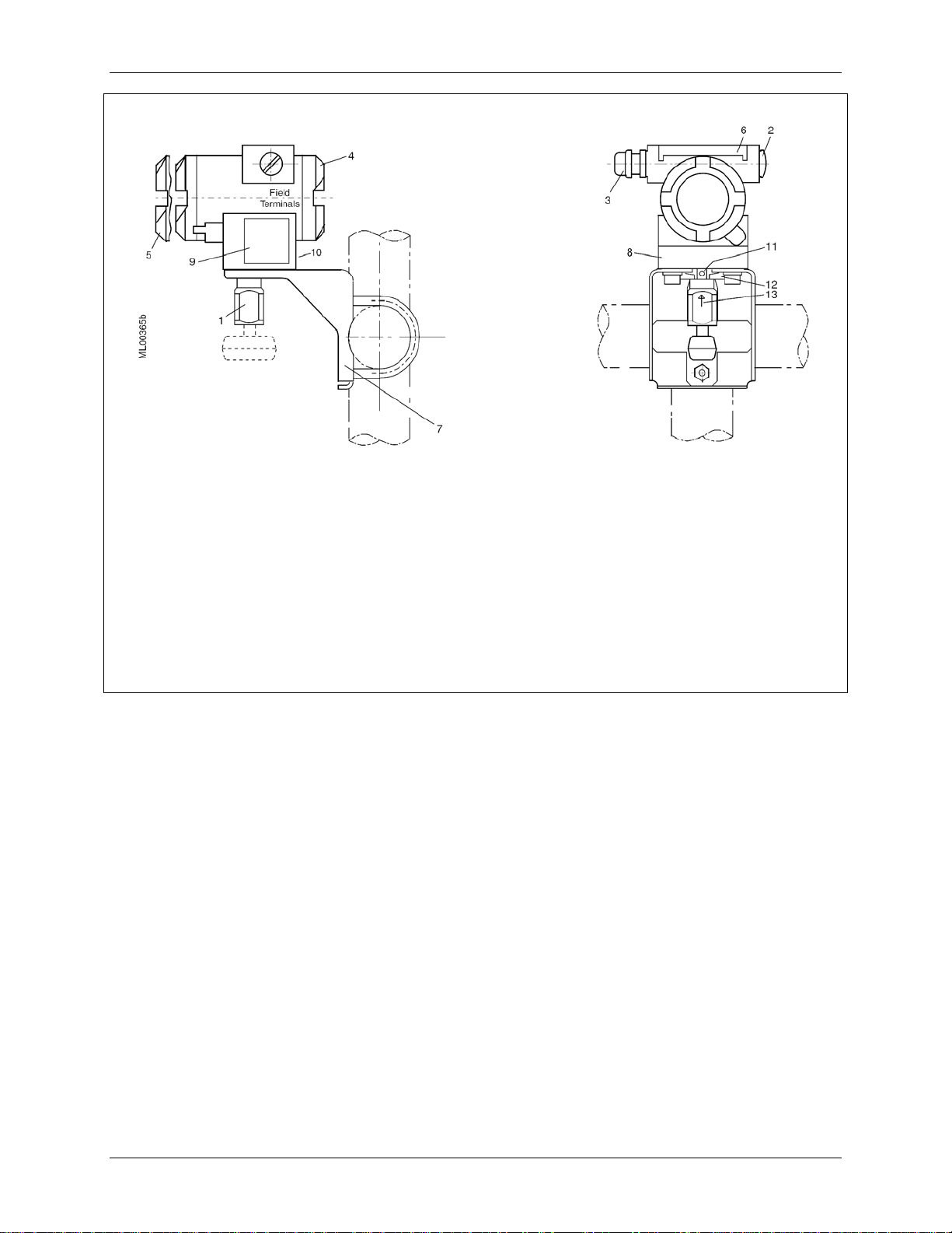
1
Process connection:
1/2-NPT, connection shank G1/2A
Oval flange
2
Blanking plug
3
Electrical connection:
Screwed gland M20 x 1.5
Screwed gland 1/2-14NPT
4
Field terminals; remove enclosure cap for
access
5
Electronics module and display; remove
enclosure cap for access
FIGURE 1-1 Gauge Construction, Pressure and Absolute Pressure Models
6
Hinged access cover over magnetic
pushbuttons
7
Mounting bracket, optional
8
Tag plate
9
Approval plate; Rating plate on other side
10
Enclosure ground screw
11
Enclosure setscrew
12
Enclosure rotation limits
13
Enclosure rotation reference arrow; see
Section 4 for details
This Figure is for Models 7MF4033 and
7MF4233
November 2010
1-3
Introduction UMSITRPDS3-1
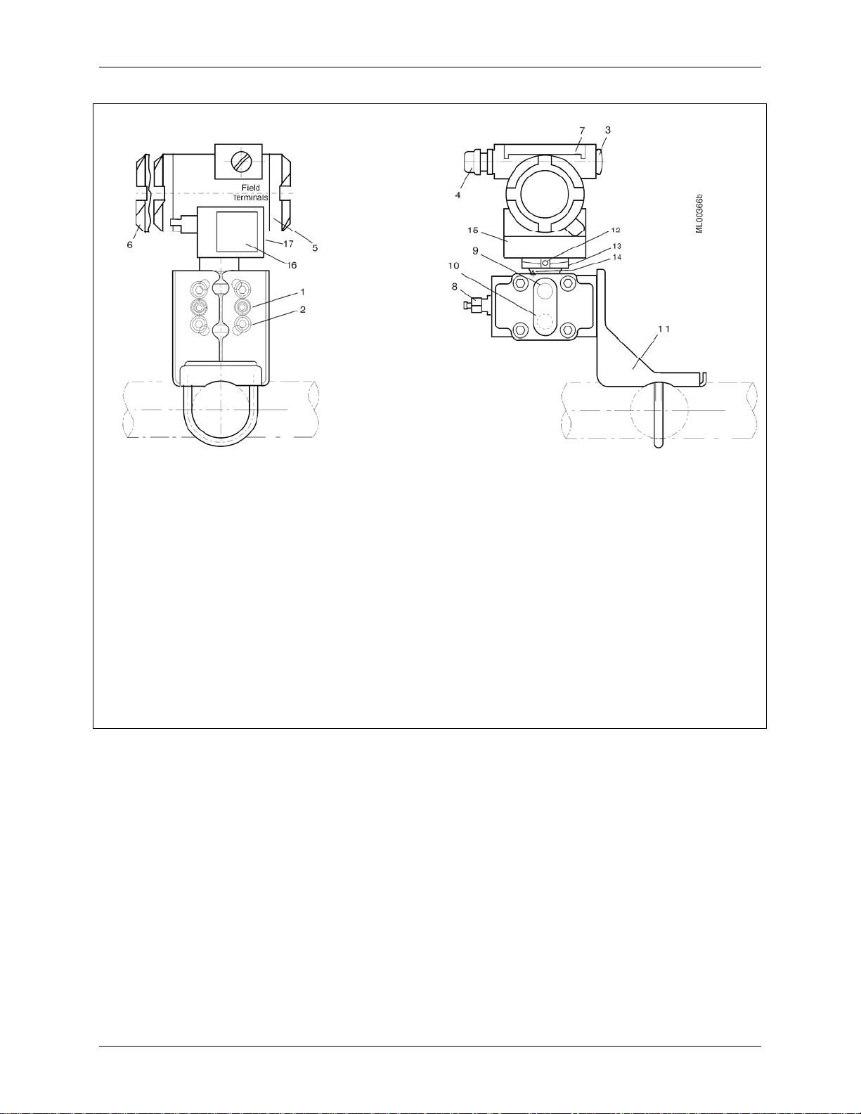
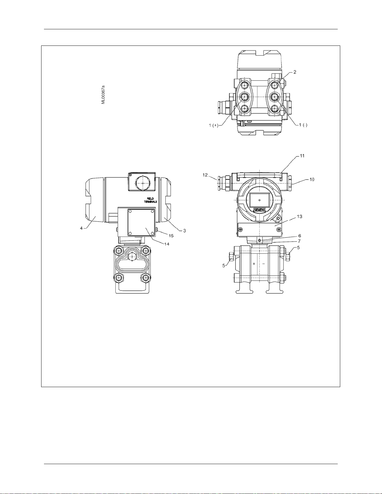
1
Process Connection 1/4-18NPT for absolute
pressure + side
2
Mounting thread M10, M12 or 7/16-20UNF
3
Blanking plug
4
Electrical connection:
Screwed gland M20 x 1.5
Screwed gland 1/2-14NPT
5
Field terminals; remove enclosure cap for
access
6
Electronics module and display; remove
enclosure cap for access
7
Hinged access cover over magnetic
pushbuttons
8
Sealing screw with vent shown (optional)
9
Side vent for measuring liquid
FIGURE 1-2 Differential Construction; Differential, Flow, and Absolute Models
10
Side vent for measuring gas (supplement H02)
11
Mounting bracket, optional
12
Enclosure setscrew
13
Enclosure rotation limits (see 14 reference
arrow)
14
Enclosure rotation reference arrow; see
Section 4 for details
15
Tag plate
16
Approval plate; Rating plate on other side
17
Enclosure ground screw
This Figure is for Models 7MF4333, 7MF4433,
and 7MF4533.
November 2010
1-4
UMSITRPDS3-1 Introduction
1
Process connection 1/4-18NPT
2
Mounting thread M10 or 7/16-20UMF
3
Field terminals; remove enclosure cap for
access
4
Electronics module and display; remove
enclosure cap for access
5
Sealing screw
6
Enclosure setscrew
7
Enclosure rotation limits; enclosure
rotation reference arrow on neck (see
Section 4 for details)
10
11
12
13
14
15
FIGURE 1-3 Differential Pressure and Flow Models with H03 Option
November 2010
Blanking plug
Access cover over magnetic pushbuttons
Electrical connection:
M20 x 1.5
1/2-14NPT
Tag plate
Approval plate; Rating plate on other side
Enclosure ground screw
This Figure is for Models 7MF4433 and
7MF4533 with H03 option.
1-5
Introduction UMSITRPDS3-1
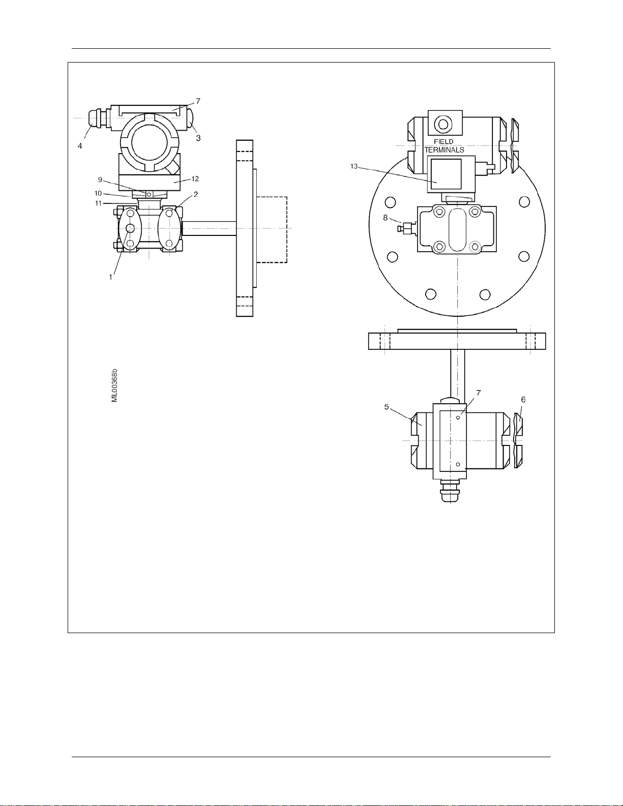
1
Process connection at low side 1/4-18NPT
2
Mounting thread M10, M12, or 7/16-20UNF
3
Blanking plug
4
Electrical connection:
M20 x1.5
1/2-14NPT
5
Field terminals; remove enclosure cap for
access
6
Electronics module and display; remove
enclosure cap for access
7
Access cover to magnetic pushbuttons
8
Sealing screw with vent shown (optional)
9
Enclosure setscrew
10
Enclosure rotation limits
11
Enclosure rotation reference arrow (not
shown; see Section 4 for details)
12
Tag plate
13
Rating plate; approval plate on other side
This Figure is for Models 7MF4633 and
7MF4812
FIGURE 1-4 Flanged Liquid Level Models
November 2010
1-6
UMSITRPDS3-1 Introduction
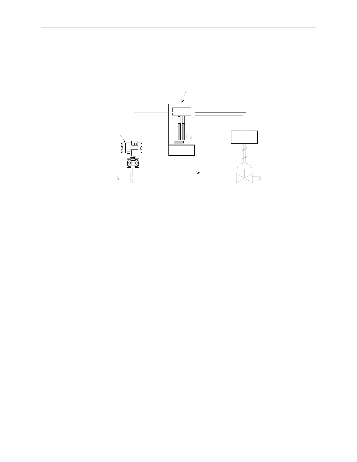
A transmitter can operate in either analog mode or digital mode, as discussed in the following paragraphs.
Analog Mode
A single transmitter is connected to a controller, recorder, or other field device. A loop known as a Pointto-Point network interconnects the instruments. Figure 1-5 shows a traditional application.
Process Automation Controller
2-Wire
4-20 mA
MG00369c
I/P
Model 771
Differential
Transmitter
2-Wire
4-20 mA
Model 353
Flow
FIGURE 1-5 Traditional Application
The HART
®
(Highway Addressable Remote Transducer) protocol is used for communication between the
transmitter and a HART Communicator, a personal computer running configuration software, or another
remote device. This is done by superimposing the HART digital signal on the analog current. HART
communications can be used to transfer a new or edited configuration, remotely monitor the process
variable, or service a transmitter.
Digital Mode
Up to 15 transmitters can be parallel connected to a Multi-Drop network using only shielded, twisted-pair
cable. The HART protocol provides communication between the transmitters and a HART-compatible
controller, recorder, or other device. Each transmitter is identified by a unique network address that is
selected during configuration.
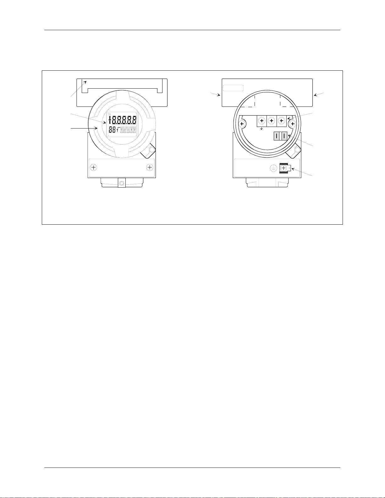
Display, Magnetic Pushbuttons, and Loop Connections
The optional display (Figure 1-6A) permits local viewing of input and output variables and status
messages, and it simplifies local configuration. Local configuration is performed using three magnetic
pushbuttons that are found beneath an access cover in the transmitter housing. Section 6 On-Line
Configuration and Operation describes use of the display and magnetic pushbuttons.
Loop connections are made to a terminal assembly with three screw terminals (Figure 1-6B). The
assembly is located within the transmitter enclosure and is accessed by removing the enclosure cap
adjacent to FIELD TERMINALS on the enclosure. The terminal assembly also has Analog Output Test
Terminals to connect an external digital milliammeter for loop troubleshooting and transmitter
calibration. Loop wiring is shown in Section 4 Installation.
November 2010
1-7
Introduction UMSITRPDS3-1
An enclosure ground connection is located on the housing beneath the field terminal enclosure cap. The
enclosure should always be grounded by a wire connected from this terminal to an earth ground, even
when a ground may be provided by metal conduit protecting the loop wiring.
2
44
1
3
+
+
MG00364b
MG00364b
+
_
-4-20mA+
1
2
3
1
Digital display, optional
2
Magnetic pushbutton access cover
3
Enclosure cap
1
Field terminals for analog output
2
Analog output test terminals
3
Enclosure ground
4
Electrical entrances; plug unused entrance
A. Digital Display B. Field Terminals
FIGURE 1-6 Digital Display and Field Terminals
Transmitters have an intrinsically safe, explosion proof, NEMA 4x (IP67/68), field mountable, hardened
enclosure. Electrical conduit connections are 1/2-14 NPT or M20 x 1.5. All process wetted materials are
316 stainless steel or better. The flush-mount process connection of the liquid level model is compatible
with standard ANSI and metric flange sizes for tanks and pipes.
November 2010
1-8
UMSITRPDS3-1 Introduction
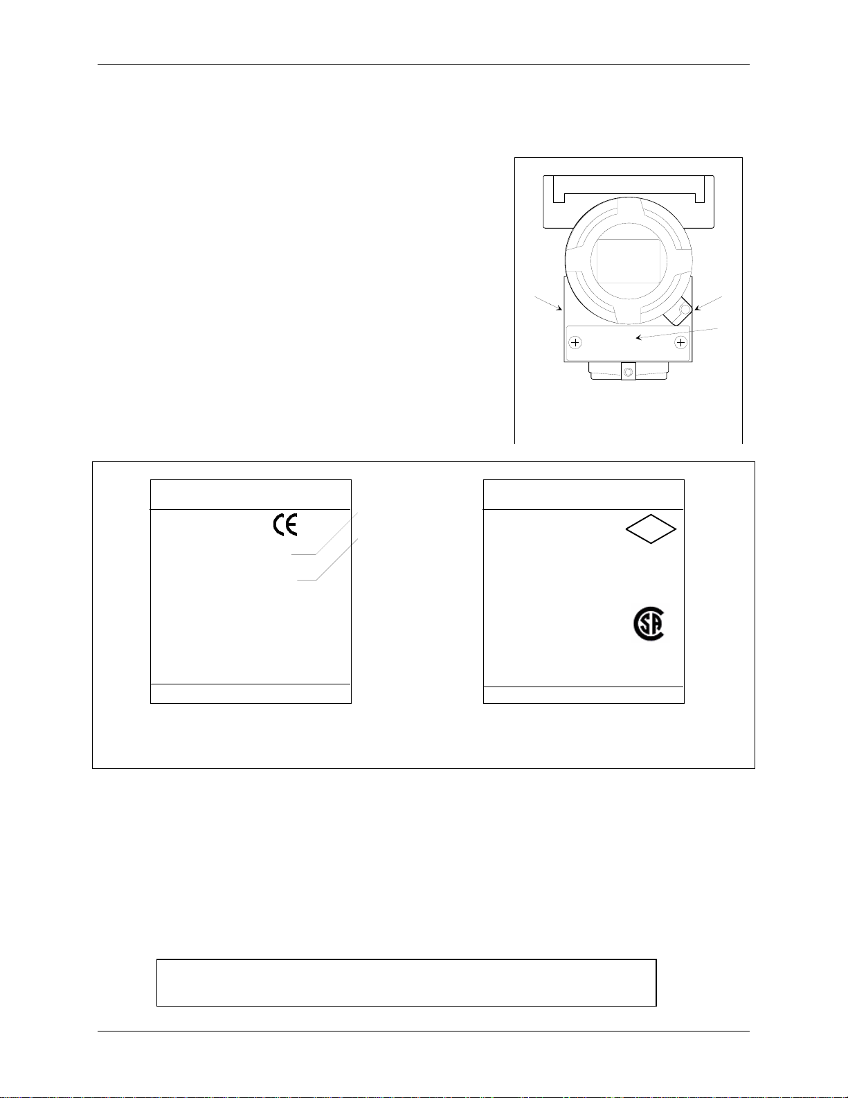
1.3 RATING, APPROVAL, AND TAG PLATES
These plates are fastened to the outside of the transmitter
enclosure, as shown at right. The rating plate shows that
transmitter’s model number, serial number, and performance
data. The approval plate shows that transmitter’s approval and
certification data. Always refer to these plates to confirm the
model number, performance data and approval and certification
data before installing or servicing a transmitter. Representative
plates are shown below.
The tag plate is fastened with two screws so it can be
removed for engraving.
SIEMENS
Springhouse, PA USA
SITRANS P
Transmitter for diff. pressure
7MF4433-1EA22-1NC6-Z
B21
Fab. Nr. IX-T411-9014869
VH :DC 10.5-45V (not intr. safe) outp.: 4-20 mA
Mat.: Connec. Diaphr. O-ring Filling
1.4404 FPM Silicon oil
Measuring span : 2.4 - 240 inH2O
Rated pressure : MWP 2300 psi
Assembled in USA / Components of France
PED:SEP
Type of protection IP 65
Rating Plate
1 Model number
2 Serial number
1
2
MG00384b
+
12
MG00353a
+
3
1 Rating plate
2 Approval plate
3 Tag plate
SIEMENS
Springhouse, PA USA
SITRANS P
(XP/DIP) or (IS)
CL I ZN 0/1 AEx ia IIC T4..T6 (FM)
Ex ia IIC T4. .T6 (CSA cert.2000.1153651)
CL I DIV 1, GP ABCD T4..T6; CL II, DIV 1, GP EFG; CL III
Vi < 30V : Ii < 100 mA : Pi < 0.75 W
Ci < 6 nF : Li < 0.4 mH
Per Control Dwg. A5E00072 770A
CL 1 Div 2 GP ABCD T4..T6
CL II DIV 2 GP FG; CL III
Vmax = 30 V
Ta = T4: -40..85ºC ; T6: -40..60ºC
ENCL Type 4X, seal not required
FW: 0011.03.06 HW: 02.05.01
Assembled in USA / Components of France
Approval Plate
FM
APPROVED
MG00384b
1.4 CONFIGURATION
A transmitter must be configured before use. Each transmitter is shipped with either a default
configuration or, if specified at time of order, a custom configuration defined by the user. The default
configuration may need to be edited before the transmitter is used in a loop. The configuration is stored
within the transmitter in a non-volatile memory.
A configuration can be created or edited locally at the transmitter’s magnetic pushbuttons or remotely
using the Model 275 HART Communicator.
Note: If using a Model 375 Field Communicator, see the inside of the front
cover of this manual.
November 2010
1-9

Introduction UMSITRPDS3-1
1.5 CUSTOMER/PRODUCT SUPPORT
Support is available through an online Support Request service; a link is provided in
the table at the end of this section.
When contacting Siemens for support:
• Please provide complete product information:
• For hardware, this information is provided on the product nameplate
(part number or model number, serial number, and/or version).
• For most software, this information is given in the Help > About screen.
• If there is a problem with product operation:
• Is the problem intermittent or repeatable? What symptoms have been observed?
• What steps, configuration changes, loop modifications, etc. were performed before the
problem occurred?
• What status messages, error messages, or LED indications are displayed?
• What troubleshooting steps have been performed?
• Is the installation environment (e.g. temperature, humidity) within the product’s specified
operating parameters? For software, does the PC meet or exceed the minimum requirements
(e.g. processor, memory, operating system)?
• A copy of the product Service Instruction, User’s Manual, or other technical publication should be at
hand. The Siemens public Internet site (see the table) has current revisions of technical literature, in
Portable Document Format, for downloading.
• To send an instrument to Siemens for warranty or non-warranty service, call Customer Service and
Return to request a Return Material Authorization (RMA); see the table below.
IMPORTANT
An instrument must be thoroughly cleaned (decontaminated) to remove any process
materials, hazardous materials, or blood-borne pathogens prior to return for repair. Read
and complete the Siemens RMA form(s).
For support and the location of your local Siemens representative, refer to the table below for the URL of
the Process Instrumentation (PI) portion of the Siemens public Internet site. Once at the site, click
Support in the right column and then Product Support. Next select the type of support desired: sales,
technical (see the table below), documentation, or software.
Online Support Request http://www.siemens.com/automation/support-request
Technical Support 1-800-333-7421; 8 a.m. to 4:45 p.m. eastern time, Monday through Friday (except
holidays)
Customer Service & Returns 1-800-365-8766 (warranty and non-warranty)
Public Internet Site http://www.usa.siemens.com/pi
Technical Publications
in PDF
Click the above link to go to the PI home page. Click Support and then Manuals
and then, under “Additional Manuals,” select the product line (e.g. Control
Solutions)
November 2010
1-10
UMSITRPDS3-1 Model 275 Universal Hart Communicator
2.0 MODEL 275 UNIVERSAL HART COMMUNICATOR
The Model 275 Universal HART Communicator is a handheld interface that provides a common
communication link to SITRANS P transmitters and other HART-compatible instruments.
This section describes HART Communicator connections, liquid crystal display, keypad, and on-line and
off-line menus. It also provides overviews of many Communicator functions. The Communicator is
shown in Figure 2-1. For information about the Communicator’s battery pack, Memory Module, Data
Pack, and maintenance procedures, refer to the manual supplied with the Communicator.
2.1 INTRODUCTION
The HART Communicator connects to and communicates with a transmitter or other HART device using
a 4-20 mA loop, provided a minimum load resistance of 250Ω is present between the Communicator and
the power supply. The Communicator uses Bell 202 frequency-shift keying (FSK) to impose highfrequency digital signals on a standard 4-20 mA current loop. Because no net energy is added to the loop,
HART communication does not disturb the 4-20 mA signal.
The Communicator can be used in hazardous and non-hazardous locations.
WARNING
Explosion can cause death or serious injury.
Before connecting the HART Communicator in an
explosive atmosphere, be sure that the instruments in
the loop are installed in accordance with intrinsically
safe or non-incendive field wiring practices.
Refer to the Communicator nameplate and the supplied
manual for certifications and approvals before
connecting, or making a connection to the serial port or
NiCad charger port on the Communicator.
2.2 COMMUNICATOR CONNECTIONS
The Communicator can interface with a transmitter from the control room, the instrument site, or any
wiring termination point in the loop. Connections are made through a supplied 40" (1m) cable (dual
banana plug to mini-hook test clips). The connection panel also may have a jack for the optional NiCad
charger, and it has a serial port for a future connection to a personal computer (PC).
To interface with a transmitter or other HART device, connect the HART Communicator in parallel with
the instrument or load resistor. The connections are non-polar. For intrinsically safe FM and CSA wiring
connections, see the manual supplied with the Communicator.
Figure 2-2 illustrates typical wiring connections between the HART Communicator and a loop with a
transmitter or other HART-compatible device in a loop. The Communicator is quickly connected into a
transmitter loop.
November 2010
2-1
Model 275 Universal Hart Communicator UMSITRPDS3-1
9
10
11
12
1
2
7
F1 F2 F3 F4
3
HART Communicator
4
5
6
MG00360a
I
O
A B C D E F G H I
13
2
J K L
8
M N O P Q R
4
5
V W X Y Z /
S T U
78
# % &
< >
.
0
6
9
+
:
*
_
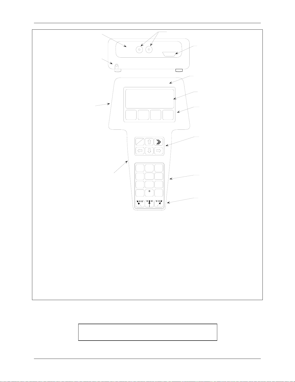
Model 275 Universal HART Communicator
1
Liquid Crystal Display (LCD), 8 lines, 21 characters per line
2
Function Keys (softkeys), software defined
3
Action Keys – ON/OFF (I/O), Up Arrow, Quick Access Key (>>>), Previous Menu (Back, left arrow),
4
Down Arrow, Select (Forward, right arrow)
Alphanumeric Keys (keypad number sequence may be different from that shown)
5
Shift Keys – Use to select alphabetic and other characters above a number, period, or dash.
6
Communicator Nameplate – On back of device. See nameplate for certifications and approvals
7
before connecting in a hazardous location.
Communicator model number and serial number on back
8
Connection panel.
9
Non-polar loop connection; dual banana plug
10
Serial port for PC connection; DB9
11
NiCad Charger Jack, optional
12
FIGURE 2-1 Model 275 Universal HART Communicator
Note: If using a Model 375 Field Communicator, see the
inside of the front cover of this manual.
November 2010
2-2
UMSITRPDS3-1 Model 275 Universal Hart Communicator
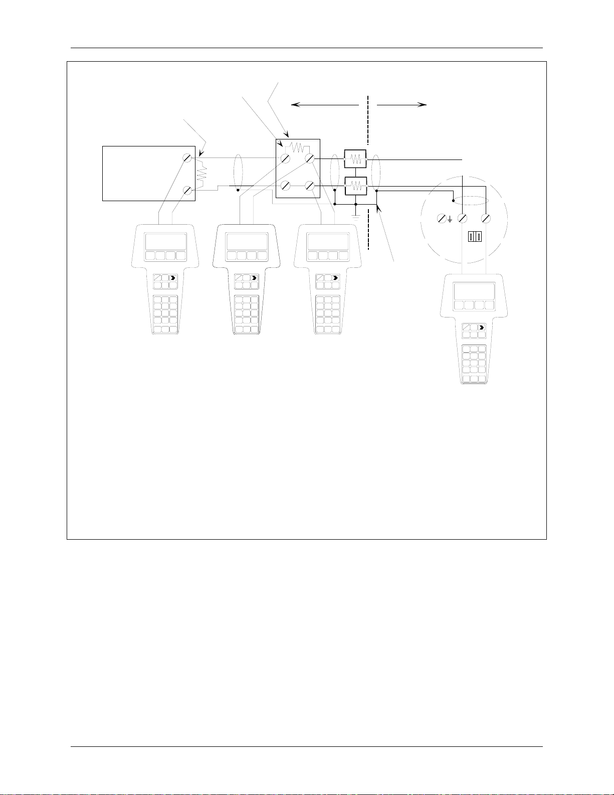
Range Resistor
250, typical
Controller,
Recorder, or
Other 1-5 Vdc
Device; See
Note 2
I
Current Sense
Resistor 250 to
1100; See Note 3
+
_
O
See
Note 1
Circuit
Junction
MG00359a
Non-Hazardous
Location
Hazardous
Location
Transmitter
Terminals
_
+
- +
4-20 mA
See Note 4
IOI
O
I
O
I
See
O
Note 1
Notes:
1 HART Communicator Connections:
Non-hazardous location – Connect as shown above.
Hazardous location – Refer to Communicator nameplate and the manual supplied with the
Communicator for certifications and approvals before connecting.
The HART Communicator is a non-polar device.
2 The System Power Supply may be part of the host input device or a separate device.
3 Network resistance equals the sum of the barrier resistances and the current sense resistor.
Minimum value is 250!; maximum value is 1100!.
4 Supply and return barriers are shown. Interconnect all cable shields and ground only at the barriers.
FIGURE 2-2 HART Communicator Connections to a Transmitter Loop
November 2010
2-3

Model 275 Universal Hart Communicator UMSITRPDS3-1
2.3 CONTROLS OVERVIEW
As shown in Figure 2-1, the front of the HART Communicator has five major functional areas: liquid
crystal display (LCD), function keys, action keys, alphanumeric keys, and shift keys. The next five
sections describe how each of these functional areas is used to enter commands and display data.
2.3.1 Liquid Crystal Display
The liquid crystal display (LCD) is an 8-line by 21-character display that provides communication
between the user and a connected device. When the HART Communicator is connected to a SITRANS P
transmitter or other HART-compatible device, the top line of the Online menu displays the model name
of the device and its tag. A typical display is shown below. The actual display content can vary with the
device type and manufacturer.
SITRANS P
Online "
1->Pres
2 Type
3 Device setup
HELP |SAVE
Note: If using a Model 375 Field
Communicator, see the inside of
the front cover of this manual.
The bottom line of each menu is reserved for dynamic labels for the software-defined function keys, F1F4, which are found directly below the display. More information on software-defined function keys is
given in the next section.
2.3.2 Software-Defined Function Keys
The four software-defined function keys (softkeys), located below the LCD and marked F1 through F4,
are used to perform software functions as indicated by the dynamic labels. Pressing the function key
immediately beneath a label activates the displayed function.
The label appearing above a function key indicates the function of that key for the current menu
. For
example, in menus providing access to on-line help, the HELP label appears above the F1 key. In menus
providing access to the Online menu, the HOME label appears above the F3 key. Table 2-1 lists these
labels and describes what happens when each function key is pressed.
November 2010
2-4

UMSITRPDS3-1 Model 275 Universal Hart Communicator
TABLE 2-1 Function Keys with Their Labels and Actions Performed
F1 F2 F3 F4
HELP
Access on-line help
RETRY
Try to reestablish
communication
EXIT
Leave the current menu
YES
Answer to yes/no
question
ALL
Include current Quick
Access Key item on
Quick Access Key
menu for all devices
ON/OFF
Activate or deactivate a
bit-enumerated binary
variable
DEL
Delete current
character or Quick
Access Key menu item
SEND
Send configuration
data to device
PGUP
Move up one help
screen
PREV
Go to previous
message in a list of
messages
ABORT
Terminate current task
ESC
Leave a value
unchanged
QUIT
Terminate session
because of a
communication error
PGDN
Move down one help
screen
NEXT
Go to next message in
a list of messages
OK
Acknowledge
information on the
LCD
ENTER
Accept user-entered
data
EXIT
Leave the current menu
NO
Answer to yes/no
question
ONE
Include Quick Access
Key item for one
device
NEXT
Go to the next variable
in off-line edit
FILTR
Open customization
menu to sort
configurations
XPAND
CMPRS
SAVE
Save information to
Communicator
MARK
Toggle marked
variable in
configuration to be sent
to a field device
Opens detailed
configuration
information
Closes detailed
configuration
information
HOME
Go the top menu in the
device description
BACK
Go back to the menu
from which HOME
was pressed
EDIT
Edit a variable value
ADD
Add current item to
Quick Access Key
menu
November 2010
2-5

Model 275 Universal Hart Communicator UMSITRPDS3-1
2.3.3 Action Keys
Directly beneath the LCD and software-defined function keys are six blue, white, and black action keys.
Each has a specific function as described below:
I
ON/OFF KEY – Use to power-up the Communicator. When the Communicator is turned on,
it automatically searches for a HART-compatible device on the 4-20 mA loop. If no device is
O
found, the Communicator displays the Main menu:
If a SITRANS P transmitter is found, the Communicator displays the Online menu:
UP ARROW KEY – Use to move the cursor up through a menu or list of options or to scroll
through lists of available characters when editing fields that accept both alpha and numeric
data.
DOWN ARROW KEY – Use to move the cursor through a menu or a list of options or to
scroll through lists of available characters when editing fields that accept alpha and numeric
data.
LEFT ARROW/PREVIOUS MENU KEY – Use to move the cursor to the left or back to the
previous menu.
HART Communicator
1#Offline
2 Online
3 Frequency device
4 Utility
SITRANS P
Online "
1#Pres
2 Type
3 Device setup
HELP |SAVE
RIGHT ARROW/SELECT KEY – Use to move the cursor to the right or to select a menu
option.
QUICK ACCESS KEY (HOT KEY) – When the Communicator is on and connected to a
HART-compatible device, pressing the Quick Access Key instantly displays the Quick Access
Key menu of user-defined options. When the Communicator is off and the Quick Access Key
is pressed, the Communicator automatically powers-up and displays the Quick Access Key
menu.
See Section 2.6 for more information on using the Quick Access Key.
November 2010
2-6

UMSITRPDS3-1 Model 275 Universal Hart Communicator
IMPORTANT
When performing certain operations, the message “OFF KEY DISABLED”
indicates that the Communicator cannot be turned off. This feature helps prevent
accidental shutoff of the Communicator while the output of a device is fixed or a
device variable is being edited.
2.3.4 Alphanumeric and Shift Keys
The alphanumeric keys perform two functions: (1) rapid selection of menu options and (2) data entry. The
shift keys located below the alphanumeric keys on the keypad are used during data entry to select from
among the characters available above each number.
2.3.4.1 Rapid Selection of Menu Options
From any menu, use the keypad to select available options in two ways. First, use the UP or DOWN
arrow keys, followed by the RIGHT ARROW/SELECT key, to access available options displayed on the
LCD.
As an alternative, use the rapid select feature. Simply press the number on the alphanumeric keypad that
corresponds to the desired menu option. For example, to quickly access the Utility menu from the Main
menu, simply press “4” on the keypad.
2.3.4.2 Data Entry
Some menus require data entry. Use the alphanumeric and shift keys to enter all alphanumeric
information into the HART Communicator. Pressing an alphanumeric key alone while editing causes the
large character in the center of the key (number 0-9, decimal point, or dash) to be entered.
Pressing and releasing a shift key activates shift and causes the appropriate arrow icon ($, %, or &) to
appear in the upper right-hand corner of the LCD. When shift is activated, the indicated alpha characters
or symbols are entered when the keypad is used.
Example
To enter a number, such as “7,” simply press the number key.
To enter one of the small characters appearing above the large numeral (i.e., a letter, space, or
mathematical symbol), first press and release
the corresponding shift key at the bottom of the keypad,
then press the desired alphanumeric key. To enter the letter “E,” press and release the middle shift key,
then press the number “2” key.
To deactivate a shift key without entering a letter, space, or mathematical symbol, simply press that shift
key again.
November 2010
2-7
Model 275 Universal Hart Communicator UMSITRPDS3-1
A
2.4 GETTING TO KNOW THE COMMUNICATOR
The HART Communicator operates either on-line or off-line. Off-line operation is used to create or edit a
configuration that can then be downloaded to a HART device, such as a transmitter. On-line operation is
used to download a configuration to a HART device, upload a configuration, edit HART device operating
parameters, and monitor process values.
For off-line operation, the Communicator need not be connected to a HART device. On-line operation
requires a connection to a powered HART device.
The menu that appears first when the Communicator is turned on depends on whether the Communicator
is connected to a powered HART device.
• Communicator not connected - Main menu (off-line operation)
• Communicator connected - Online menu (on-line operation)
To work off-line when connected to a powered loop, access the Main menu from the Online menu by
pressing the LEFT ARROW/PREVIOUS MENU key.
Note
Communicator internal operation is controlled by firmware. Consequently,
operation will depend upon the firmware version and the installed device drivers,
as discussed in this section.
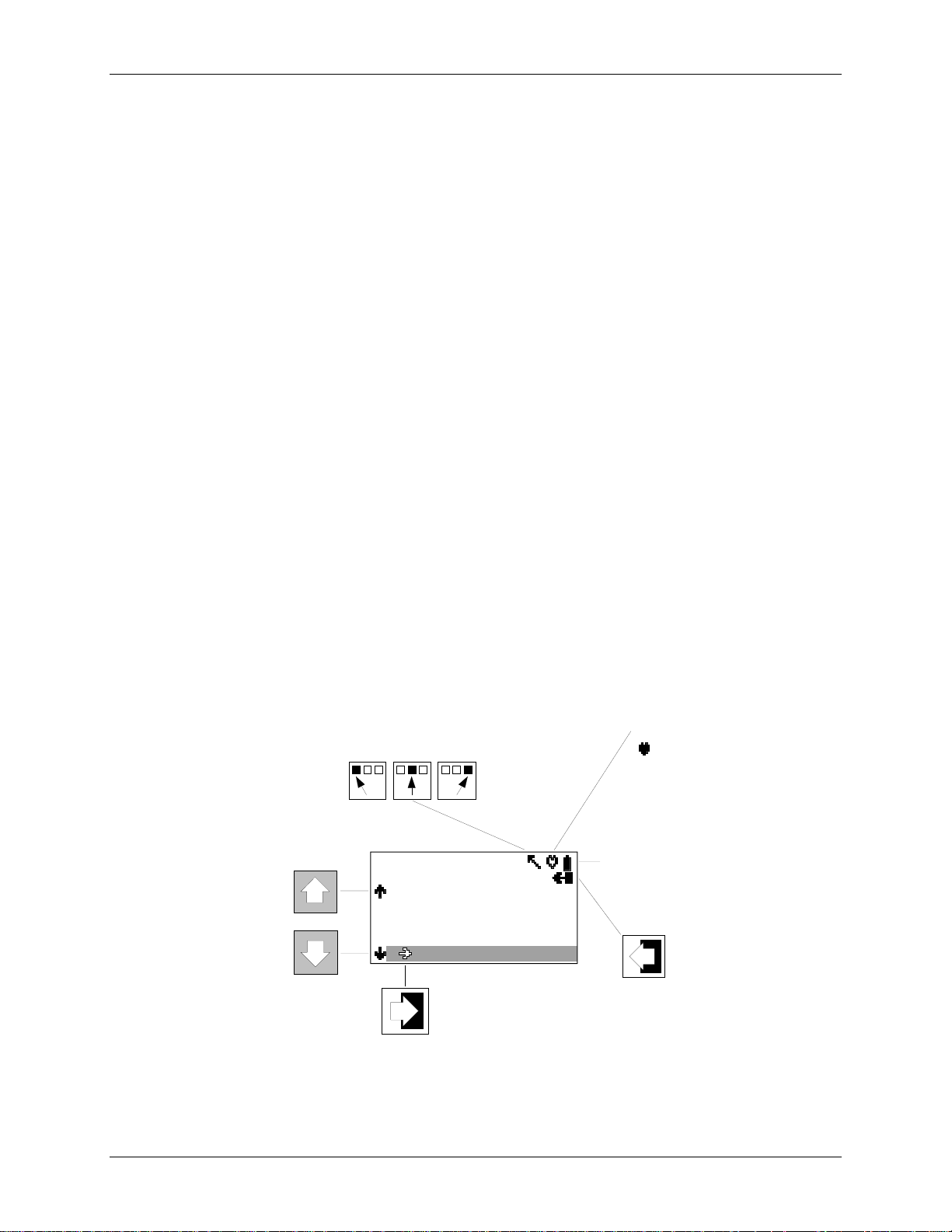
2.4.1 Display Icons
Several different symbols (icons) appear on the LCD to show the state of the Communicator and provide
visible response to actions of the user. Figure 2-3 shows the display icons and how they relate to keypad
functions.
HART Communication
( indicates connected
device is configured in
the burst mode)
ccess Additional
Menu Items
HART Communicator
Device Info
2 Dev Type
3 Dev ID 0
4 Tag
5 MM/DD/YY 10/10/10
6 Write Protect Yes
Low Battery
Access
Previous
Menu
X03034S1
FIGURE 2-3 HART Communicator Display Icons
November 2010
2-8
 Loading...