


Siemens 7MF4033 series, 7MF4233 series, 7MF4533 series, 7MF4912 series, 7MF4333 series User Manual
Siemens
Energy & Au tomation
SITRANS P, Series DSIII Transmitter
Pressure, Differential Pressure,
Flanged Level, and Absolute Pressure
USER'S MANUAL
UMSITRPDS3-1
Rev. 6
November 2005
Supersedes Rev. 5
for
Model 7MF4*33-...

北京迪妙声科技有限公司
S
DELLSONIC
BEJING DELLSONICS SCIENCE & TECHNOLOGY L TD.
公 司 简 介
北京迪妙声科技有限公司(原名北京妙声力科技有限公司),位于北京市海淀区中关村
南大街,是与西门子公司德国总部正式签约的西门子过程仪表及分析仪器核心合作伙伴,
也是西门子北方区域规模最大、实力最强的优秀代理商。
公司主营:
一、西门子-妙声力(Milltronics)系列物位产品:超声波物位计、超声波液位差计、超声波泥水界
面计、超声波明渠流量计、雷达物位计、射频导纳物位计、射频导纳油水界面计、;射频导纳物位开关、
音叉式物位开关、阻旋式物位开关;皮带称、固体质量流量计、冲板流量计等。
二、西门子过程仪表产品:电磁流量计、质量流量计、超声波流量计、 温度变送器、压力变送器、
阀门定位器、气体分析仪等。
三、德国 UWT 公司的阻旋式料位开关、音叉式料位开关、重锤式料位计等产品。
四、自行研发生产超声波液位计、温度变送器、压力变送器、数显表及油田专用仪器等产品。
成立于 1954 年的西门子-妙声力公司(Milltronics)是世界公认的超声波物位测量领域
的领导者,全球最大的超声波物位仪表生产厂家,在超声波、雷达、电容技术领域拥有超过 60
项专利,超声波产品的综合性能指标经美国《控制》杂志评比,其综合性能名列全球第一!
作为西门子公司长期稳定的代理商,我公司有着 10 余年产品的销售和服务经验,无论
从专业技术水平、现货及备件库存量、售后服务质量、仪表维护以及故障产品国内维修能力
等方面,都具备显著的优势。尤其是我公司一流的技术支持和高效率高品质的服务体系,在
业界具有很高的知名度。
如果您需要相关的产品,需要咨询技术问题,需要值得信赖的合作伙伴,敬请来电垂询!
商务部总机电话:010-88579530/31/32/33,88579597,88571841,81968099(小灵通)
传真:总机转 50
谢谢您的合作与支持!
地址:北京海淀区魏公村街 1 号韦伯豪家园 3-3-702 (100081) http://www.dellsonics.com
电话:010-88579530/31/32/33,88579597,88571841 传真:总机转 50 E-mail:sales@dellsonics.com

IMPORTANT
MODEL 275 HART COMMUNICATOR AND
MODEL 375 FIELD COMMUNICATOR
Many procedures, screens, and wiring diagrams shown in this manual feature the Model 275 HART
Communicator.
The Model 375 Field Communicator is now available. Procedures and screens are similar to those for the
Model 275, however, there are significant differences and an online Configuration Map for use with the
Model 375 is provided at the back of this manual.
Transmitter model and firmware version can affect the displays, display options, and Configuration Maps.
Whether using the Model 275 or the Model 375, be sure to read the manual supplied by the manufacturer
before installing or using the device. Refer to the devices nameplate for hazardous are
approvals and other important information.
APPLICATION AND MODEL QUICK LOCATOR
The following table provides an overview of measurement categories and available models. For details
pertaining to a particular model, see its model designation table and its specification table in Section 9
Model Designations and Specifications. To quickly locate other information, refer to the Table of
Contents.
Measurement Models Model Designation Specifications Dimensions
a certifications and
Absolute or Gauge
Pressure
Differential Pressure
Level (Flange)
7MF4033
7MF4233
7MF4333
7MF4433
7MF4533
7MF4633
7MF4912
Table 9-1
Table 9-2
Table 9-3
Table 9-4
Table 9-5
Table 9-6
Table 9-6
Table 9-15
Table 9-16
Table 9-16
Table 9-15
Table 9-15
Table 9-16
Table 9-16
Figure 9-1
Figure 9-1
Figure 9-2
Figure 9-2 or 9-3
Figure 9-2 or 9-3
Figure 9-4
Figure 9-4

UMSITRPDS3-1 Contents
TABLE OF CONTENTS
Section and Title Page
Conventions, Symbols, and General Information.................................................................viii
1.0 INTRODUCTION...................................................................................................1-1
1.1 CONTENTS......................................................................................................................1-1
1.2 PRODUCT DESCRIPTION ..............................................................................................1-2
1.3 RATING, APPROVAL, AND TAG PLATES......................................................................1-9
1.4 CONFIGURATION ...........................................................................................................1-9
1.5 PRODUCT SUPPORT ...................................................................................................1-10
2.0 MODEL 275 UNIVERSAL HART COMMUNICATOR...........................................2-1
2.1 INTRODUCTION..............................................................................................................2-1
2.2 COMMUNICATOR CONNECTIONS................................................................................2-1
2.3 CONTROLS OVERVIEW .................................................................................................2-4
2.3.1 Liquid Crystal Display ................................................................................................2-4
2.3.2 Software-Defined Function Keys ...............................................................................2-4
2.3.3 Action Keys................................................................................................................2-6
2.3.4 Alphanumeric and Shift Keys.....................................................................................2-7
2.3.4.1 Rapid Selection of Menu Options........................................................................2-7
2.3.4.2 Data Entry ...........................................................................................................2-7
2.4 GETTING TO KNOW THE COMMUNICATOR ................................................................2-8
2.4.1 Display Icons .............................................................................................................2-8
2.4.2 Menu Structure ..........................................................................................................2-9
2.4.3 Reviewing Installed Devices......................................................................................2-9
2.5 MAIN MENU...................................................................................................................2-11
2.5.1 Offline Menu ............................................................................................................2-12
2.5.1.1 New Configuration.............................................................................................2-13
2.5.1.2 Saved Configuration..........................................................................................2-16
2.5.2 Online Menu ............................................................................................................2-18
2.5.3 Frequency Device Menu..........................................................................................2-21
2.5.4 Utility Menu..............................................................................................................2-21
2.5.4.1 Configure Communicator ..................................................................................2-21
2.5.4.2 System Information ...........................................................................................2-22
2.5.4.3 Listen for PC .....................................................................................................2-22
2.5.4.4 Storage Location ...............................................................................................2-22
2.5.4.5 Simulation .........................................................................................................2-22
2.5.4.6 Selftest ..............................................................................................................2-22
2.6 USING THE QUICK ACCESS KEY................................................................................2-23
2.6.1 Adding Quick Access Key Options ..........................................................................2-24
2.6.2 Deleting Quick Access Key Options ........................................................................2-25
3.0 PRE-INSTALLATION TEST .................................................................................3-1
3.1 PROCEDURE ..................................................................................................................3-1
3.1.1 Test Equipment..........................................................................................................3-2
3.2 ESTABLISHING COMMUNICATION ...............................................................................3-3
3.3 TESTING THE TRANSMITTER........................................................................................3-3
3.4 REVIEWING CONFIGURATION DATA ...........................................................................3-4
3.5 CHECKING TRANSMITTER OUTPUT ............................................................................3-4
4.0 INSTALLATION....................................................................................................4-1
November 2005
i

Contents UMSITRPDS3-1
4.1 EQUIPMENT DELIVERY AND HANDLING .....................................................................4-1
4.1.1 Receipt of Shipment ..................................................................................................4-1
4.1.2 Storage ......................................................................................................................4-1
4.2 ENVIRONMENTAL CONSIDERATIONS .........................................................................4-2
4.3 PRE-INSTALLATION CONSIDERATIONS AND CALCULATIONS.................................4-2
4.3.1 Mechanical ................................................................................................................4-2
4.3.2 Electrical ....................................................................................................................4-3
4.3.3 Impulse Piping for Absolute and Differential Models .................................................4-4
4.3.4 Transmitter Operating Mode and Network Type......................................................4-10
4.3.4.1 Analog Mode .....................................................................................................4-10
4.3.4.2 Digital Mode ......................................................................................................4-14
4.3.5 Power Supply Requirements ...................................................................................4-14
4.3.5.1 Point-to-Point Network ......................................................................................4-16
4.3.5.2 Multi-Drop Network ...........................................................................................4-17
4.3.6 Determining Network (Loop) Length........................................................................4-17
4.3.6.1 Cable Capacitance............................................................................................4-17
4.3.6.2 Maximum Cable Length Calculation .................................................................4-18
4.3.7 Network Junctions ...................................................................................................4-19
4.3.8 Safety Barriers.........................................................................................................4-19
4.3.9 Connection of Miscellaneous Hardware ..................................................................4-20
4.3.10 Shielding and Grounding .......................................................................................4-21
4.4 MECHANICAL INSTALLATION .....................................................................................4-22
4.4.1 Pipe Mounting, Differential and Gauge Construction...............................................4-22
4.4.2 Direct Mounting to Process, Model 7MF4433 or 7MF4533 .....................................4-24
4.4.3 Flange Mounting, Model 7MF4633/7MF4912..........................................................4-25
4.5 MECHANICAL INSTALLATION, All Models...................................................................4-27
4.5.1 Enclosure Rotation ..................................................................................................4-27
4.5.2 Display Orientation ..................................................................................................4-28
4.5.3 Electrical Conduit and Cable Installation .................................................................4-29
4.5.3.1 Conduit..............................................................................................................4-29
4.5.3.2 Cables ...............................................................................................................4-30
4.5.3.3 Access to Transmitter Terminal Compartment..................................................4-30
4.6 ELECTRICAL INSTALLATION.......................................................................................4-31
4.7 HAZARDOUS AREA INSTALLATION............................................................................4-33
5.0 POST-INSTALLATION TEST...............................................................................5-1
5.1 TEST EQUIPMENT..........................................................................................................5-1
5.2 INSTALLATION REVIEW.................................................................................................5-1
5.3 EQUIPMENT CONNECTION...........................................................................................5-2
5.4 VERIFICATION ................................................................................................................5-3
5.4.1 Communication Test..................................................................................................5-3
5.4.2 Transmitter Selftest....................................................................................................5-3
5.4.3 Loop Test...................................................................................................................5-4
5.5 TRANSMITTER ZERO AND SHUTOFF VALVE MANIPULATION..................................5-5
5.5.1 Absolute Pressure .....................................................................................................5-5
5.5.1.1 Measuring Gases ................................................................................................5-6
5.5.1.2 Measuring Vapor and Liquid ...............................................................................5-7
5.5.2 Differential Pressure and Flow...................................................................................5-8
5.5.2.1 Measuring Gases ................................................................................................5-8
5.5.2.2 Measuring Liquids ...............................................................................................5-9
5.5.3 Measuring Vapor .....................................................................................................5-11
6.0 ON-LINE CONFIGURATION AND OPERATION .................................................6-1
November 2005
ii

UMSITRPDS3-1 Contents
6.1 LOCAL OPERATION AND DISPLAY ...............................................................................6-1
6.1.1 Digital Display............................................................................................................6-1
6.1.2 Numeric Display.........................................................................................................6-2
6.1.3 Unit/Bargraph Display................................................................................................6-3
6.1.4 Error Message ...........................................................................................................6-3
6.1.5 Output Signal Range .................................................................................................6-3
6.1.6 Mode Display............................................................................................................6-4
6.2 LOCAL OPERATION WITH THE MAGNETIC PUSHBUTTONS .....................................6-5
6.2.1 Cancel Pushbutton Disable and Write Protection......................................................6-7
6.2.2 Set/Adjust Zero and Full Scale ..................................................................................6-7
6.2.2.1 Theoretical Relationships....................................................................................6-7
6.2.2.2 Practical Applications..........................................................................................6-9
6.2.3 Electric Damping......................................................................................................6-10
6.2.4 Blind Setting of Zero and Full Scale ........................................................................6-10
6.2.4.1 Theoretical Relationships..................................................................................6-10
6.2.4.2 Practical Applications........................................................................................6-11
6.2.5 Zero Adjustment (Position Correction).....................................................................6-12
6.2.5.1 Zero-Point Alignment at Absolute Pressure ......................................................6-12
6.2.6 Fixed Current Output ...............................................................................................6-13
6.2.7 Failure Current.........................................................................................................6-13
6.2.8 Pushbutton and Function Disable............................................................................6-14
6.2.9 Flow Measurement (Differential Pressure only).......................................................6-14
6.2.10 Select Measured Value to be Displayed................................................................6-16
6.2.11 Select the Displayed Input Pressure Engineering Unit..........................................6-16
6.3 LOCAL OPERATION WITHOUT A DISPLAY OR WITH ACTIVATED KEYLOCK.........6-18
6.3.1 Set Zero and Full Scale ...........................................................................................6-18
6.4 REMOTE CONFIGURATION AND OPERATION BY HART..........................................6-20
6.4.1 Process Data ...........................................................................................................6-20
6.4.2 Setting Zero and Full Scale .....................................................................................6-21
6.4.3 Blind Setting of Zero and Full Scale ........................................................................6-21
6.4.4 Zero Adjustment for Position Correction..................................................................6-21
6.4.5 Electric Damping......................................................................................................6-22
6.4.6 Fast Measured Value Acquisition (fast response mode) .........................................6-22
6.4.7 Fixed Current Output ...............................................................................................6-23
6.4.8 Fault Current............................................................................................................6-23
6.4.9 Disabling the Transmitter Magnetic Pushbuttons and Write Protection...................6-24
6.4.10 Measured Value Display........................................................................................6-25
6.4.11 Select Pressure Engineering Units........................................................................6-25
6.4.12 Display/Bargraph ...................................................................................................6-25
6.4.13 Sensor Trim ...........................................................................................................6-26
6.4.13.1 Trimming the Lower Sensor Adjustment Point................................................6-26
6.4.13.2 Trimming the Upper Sensor Adjustment Point................................................6-27
6.4.14 D/A Trim.................................................................................................................6-28
6.4.15 Transmitter Current Adjustment.............................................................................6-28
6.4.16 Factory Calibration (Manufacturer Trims)..............................................................6-29
6.4.17 Device Information.................................................................................................6-30
6.4.18 Flow Measurement (Differential Pressure) ............................................................6-30
6.4.19 Diagnostic Functions .............................................................................................6-30
6.4.19.1 Operating Hours Counter ................................................................................6-31
6.4.19.2 Calibration Timer and Service Timer...............................................................6-31
6.4.19.3 Min/Max Pointer ..............................................................................................6-32
6.4.19.4 Monitoring the Saturation Current ...................................................................6-32
6.4.20 Simulation..............................................................................................................6-33
November 2005
iii

Contents UMSITRPDS3-1
6.4.21 Self Test and Master Reset ...................................................................................6-34
7.0 CALIBRATION AND MAINTENANCE .................................................................7-1
7.1 CALIBRATION .................................................................................................................7-2
7.2 PREVENTIVE MAINTENANCE........................................................................................7-3
7.2.1 Transmitter Exterior Inspection..................................................................................7-3
7.2.2 Transmitter Exterior Cleaning....................................................................................7-3
7.2.3 Transmitter Enclosure Interior Inspection..................................................................7-4
7.2.4 Transmitter Calibration ..............................................................................................7-4
7.2.5 Impulse Piping ...........................................................................................................7-4
7.3 TROUBLESHOOTING .....................................................................................................7-5
7.3.1 Analog Output............................................................................................................7-5
7.3.2 Digital Output (Communication).................................................................................7-8
7.4 ASSEMBLY REMOVAL AND REPLACEMENT ...............................................................7-9
7.4.1 Display Assembly ....................................................................................................7-11
7.4.2 Replacing the Electronics Module ...........................................................................7-12
7.4.3 Measuring Cell Assembly Removal and Replacement............................................7-13
7.4.4 Terminal Board Assembly Removal and Replacement ...........................................7-16
7.5 NON-FIELD-REPLACEABLE ITEMS.............................................................................7-16
7.6 TRANSMITTER REPLACEMENT..................................................................................7-17
7.7 MAINTENANCE RECORDS ..........................................................................................7-18
7.8 RECOMMENDED SPARE AND REPLACEMENT PARTS............................................7-18
7.9 COMPATIBILITY, Revision Numbers.............................................................................7-19
8.0 CIRCUIT DESCRIPTION ......................................................................................8-1
8.1 OVERALL OPERATION...................................................................................................8-2
8.2 PRESSURE......................................................................................................................8-2
8.3 DIFFERENTIAL PRESSURE AND FLOW .......................................................................8-3
8.4 FLANGED LEVEL ............................................................................................................8-3
8.5 ABSOLUTE PRESSURE (DIFFERENTIAL CONSTRUCTION).......................................8-4
8.6 ABSOLUTE PRESSURE (GAUGE CONSTRUCTION) ...................................................8-4
8.7 COMMUNICATION FORMAT ..........................................................................................8-5
9.0 MODEL DESIGNATIONS AND SPECIFICATIONS .............................................9-1
9.1 MODEL DESIGNATIONS.................................................................................................9-1
9.2 ACCESSORIES .............................................................................................................9-20
9.3 SPECIFICATIONS .........................................................................................................9-21
9.4 MEASURING SPANS AND OVERLOAD LIMITS ..........................................................9-29
9.5 NETWORK TOPOLOGY................................................................................................9-35
9.5.1 Two-Wire Cable.......................................................................................................9-35
9.6 HAZARDOUS AREA cLASSIFICATIONS......................................................................9-35
9.6.1 CSA Hazardous Locations Precautions...................................................................9-36
10.0 GLOSSARY......................................................................................................10-1
11.0 APPENDIX A - ONLINE CONFIGURATION MAP............................................11-1
12.0 APPENDIX B - HAZARDOUS AREA INSTALLATION....................................12-1
13.0 APPENDIX C - ELEVATION AND SUPPRESSION CORRECTIONS..............13-1
13.1 HOW ADJUSTMENT IS MADE....................................................................................13-1
13.2 ELEVATION CALCULATION EXAMPLE .....................................................................13-2
November 2005
iv

UMSITRPDS3-1 Contents
13.3 SUPPRESSION CALCULATION EXAMPLE ...............................................................13-2
13.4 RECOMMENDED METHOD ........................................................................................13-3
Warranty.....................................................................................................................W-1
LIST OF FIGURES
Figure and Title Page
1-1 Gauge Construction, Pressure and Absolute Pressure Models .........................................1-3
1-2 Differential Construction; Differential, Flow, and Absolute Models .....................................1-4
1-3 Differential Pressure and Flow Models with H03 Option ....................................................1-5
1-4 Flanged Liquid Level Models ..............................................................................................1-6
1-5 Traditional Application ........................................................................................................1-7
1-6 Display................................................................................................................................1-8
1-7 Field Terminals ...................................................................................................................1-8
2-1 Model 275 Universal HART Communicator........................................................................2-2
2-2 HART Communicator Connections to a Transmitter Loop .................................................2-3
2-3 HART Communicator Display Icons ...................................................................................2-8
2-4 Offline Menu Map .............................................................................................................2-12
2-5 SITRANS P Online Menu Map .........................................................................................2-19
2-6 Generic Online Menu Map................................................................................................2-20
3-1 Bench Test Connections.....................................................................................................3-1
3-2 Field Test Connections.......................................................................................................3-2
4-1 Differential Flow Measurement Piping for Gas and Liquid..................................................4-5
4-2 Differential Liquid Measurement Piping ..............................................................................4-6
4-3 Absolute or Gauge Pressure Measurement Piping ............................................................4-7
4-4 Steam Service, Below the Line Mounting ...........................................................................4-8
4-5 Open and Closed Tank Level Measurement, Flange Mounted Transmitters .....................4-9
4-6 Point-To-Point Network (Analog Mode) ............................................................................4-11
4-7 Procidia to Transmitter Connections (Analog Mode) ........................................................4-12
4-8 Model 353/354 to Transmitter Connections (Analog Mode) .............................................4-13
4-9 Multi-Drop Network (Digital Mode)....................................................................................4-15
4-10 Power Supply vs. Loop Resistance ................................................................................4-16
4-11 Pipe Mounting, Gauge Construction...............................................................................4-23
4-12 Pipe Mounting, Differential Construction ........................................................................4-23
4-13 Differential Construction, Position Options .....................................................................4-24
4-14 Enclosure Rotation Considerations ................................................................................4-27
4-15 Display Removal and Repositioning ...............................................................................4-28
4-16 Conduit Drain and Explosion Proof Installations.............................................................4-29
4-17 Network Conductor Terminations ...................................................................................4-32
5-1 Equipment Connection for System Checkout .....................................................................5-2
5-2 Measuring Gases................................................................................................................5-6
5-3 Measuring Vapor and Liquid...............................................................................................5-7
5-4 Measuring Gases................................................................................................................5-9
5-5 Measuring Liquids.............................................................................................................5-10
5-6 Measuring Vapor ..............................................................................................................5-11
6-1 Digital Display.....................................................................................................................6-1
6-2 Switch Point of the Square Root Characteristic................................................................6-15
6-3 Displayable Engineering Units..........................................................................................6-17
6-4 Sensor Trim ......................................................................................................................6-27
6-5 Pressure Min/Max Pointer Example .................................................................................6-32
6-6 Saturation Monitoring Examples.......................................................................................6-33
6-7 Simulation Circuit Diagram ...............................................................................................6-34
November 2005
v

Contents UMSITRPDS3-1
11-1 Online Configuration Map, Part 1 of 2 ............................................................................11-2
11-2 Online Configuration Map, Part 2 of 2 ............................................................................11-3
12-1 Control Drawing ..............................................................................................................12-2
12-2 Control Drawing ..............................................................................................................12-3
13-1 Elevated Span ................................................................................................................13-1
13-2 Suppressed Span ...........................................................................................................13-1
LIST OF TABLES
Table and Title Page
1-1 Measurements, Models and Figure References.................................................................1-2
1-2 Contact Information ..........................................................................................................1-10
2-1 Function Keys with Their Labels and Actions Performed ...................................................2-5
2-2 Communicator Firmware Device Descriptions, Rev. F2.2 ................................................2-10
2-3 Offline Menu Map Continued, “Edit individually” Options1................................................2-12
4-1 Operating Mode and Network...........................................................................................4-10
4-2 Flange And Extension Dimensions...................................................................................4-26
6-1 Operating Mode and Status Arrows....................................................................................6-2
6-2 Parameters Accessible Using the Magnetic Pushbuttons ..................................................6-6
6-3 Pushbutton and Function Disable Options .......................................................................6-14
6-4 Pushbutton and Function Disable Options .......................................................................6-24
9-1 Model 7MF4033, Model Designation ..................................................................................9-2
9-2 Model 7MF4233, Model Designation ..................................................................................9-4
9-3 Model 7MF4333, Model Designation ..................................................................................9-6
9-4 Model 7MF4433, Model Designation ...................................................................................9-8
9-5 Model 7MF4533, Model Designation .................................................................................9-10
9-6 Models 7MF4633 and 7MF4912, Model Designation .......................................................9-12
November 2005
vi

UMSITRPDS3-1 Contents
Changes for Revision 6, November 2005
Significant changes for Rev. 6 are indicated by change bars in the page margins. Some are listed below.
Section Revision
Cover Manual revision number and date changed.
Product Support Update Contact Information table.
Warranty Update warranty statements to include reference to the Operating
Hours Register.
SITRANS P, Series DS III, and Procidia are Siemens Energy & Automation, Inc. trademarks. All other trademarks are the
property of their respective owners. All product designations may be trademarks or product names of Siemens Energy &
Automation, Inc. or other supplier companies whose use by third parties for their own purposes could violate the rights of the
owners.
Siemens Energy & Automation, Inc. assumes no liability for errors or omissions in this document or for the application and use
of information included in this document. The information herein is subject to change without notice.
Procedures in this document have been reviewed for compliance with applicable approval agency requirements and are
considered sound practice. Neither Siemens Energy & Automation, Inc. nor these agencies is responsible for repairs made by
the user.
November 2005
vii

UMSITRPDS3-1 Contents
For the purpose of this manual and product labels, a qualified person is one who is familiar with the
installation, assembly, commissioning, and operation of the product, and who has the appropriate
qualifications for their activities such as:
• Training, instruction, or authorization to operate and maintain devices/systems according to the safety
standards for electrical circuits, high pressures, and corrosive, as well as, critical media.
• For devices with explosion protection: training, instruction or authorization to work on electrical
circuits for systems that could cause explosions.
• Training or instruction according to the safety standards in the care and use of suitable safety
equipment.
Scope
This manual does not purport to cover all details or variations in equipment, nor to provide for every
possible contingency to be met in connection with installation, operation, or maintenance. Should further
information be desired or should particular problems arise which are not covered sufficiently for the
purchaser’s purposes, the matter should be referred to one of the support groups listed in the Product
Support section of this manual.
The contents of this manual shall not become part of or modify any prior or existing agreement,
commitment or relationship. The sales contract contains the entire obligation of Siemens. The warranty
contained in the contract between the parties is the sole warranty of Siemens. Any statements continued
herein do not create new warranties or modify the existing warranty.
General Warnings and Cautions
WARNING
An explosion-proof device may be opened only after power is removed from the device.
An intrinsically safe device loses its license as soon as it is operated in a circuit that does not meet the
requirements of the examination certificate valid in your country.
The device may be operated with high pressure and corrosive media. Therefore, serious injury and/or
considerable material damage cannot be ruled out in the event of handling of the device.
The perfect and safe operation of the equipment is conditional upon proper transport, proper storage,
installation and assembly, as well as, on careful operation and commissioning.
The equipment may be used only for the purposes specified in this User’s Manual.
CAUTION
Electrostatic discharge can damage or cause the failure of semiconductor devices such as
integrated circuits and transistors. The symbol at right appears on a circuit board or other
electronic assembly to indicate that special handling precautions are needed.
November 2005
ix

Contents UMSITRPDS3-1
x
• A properly grounded conductive wrist strap must be worn whenever an electronics module or circuit
board is handled or touched. A service kit with a wrist strap and static dissipative mat is available
from Internet, mail order, and local electronic supply companies.
• Electronic assemblies must be stored in static protective bags when not installed in equipment.
November 2005

UMSITRPDS3-1 Introduction
1.0 INTRODUCTION
This user’s manual is for the Siemens Energy & Automation SITRANS P Series DSIII Pressure
Transmitters.
All information needed to bench test, install, configure, calibrate, and service a transmitter is included in
this user’s manual.
IMPORTANT
Save this user’s manual. It should be available to those installing, configuring,
operating, and servicing the described pressure transmitters.
1.1 CONTENTS
The user’s manual consists of a table of contents, ten sections, and three appendices. Following the table
of contents is a subsection that contains important information about the symbols that can appear in this
user’s manual and on the transmitter. The subsection also has statements about installing and servicing the
transmitter. A brief description of each major section and appendices follows.
Section 1, Introduction, describes each section in the manual and provides a brief description of the
SITRANS P Series DSIII Pressure Transmitter line. A product support section has telephone, fax, E-mail,
and Internet contact information.
Section 2, Model 275 Universal HART Communicator, describes use of the HART Communicator to test,
configure, and calibrate a transmitter.
Section 3, Pre-Installation Test, provides procedures to perform a bench test of the transmitter to ensure
proper operation of all transmitter functions. Start-up configuration is described here.
Section 4, Installation, furnishes specific information for mechanical and electrical installation of the
transmitter.
Section 5, Post-Installation Test, describes how to confirm that the transmitter has been installed correctly
- sometimes referred to as commissioning.
Section 6, On-Line Configuration and Operation, details local configuration using the magnetic
pushbuttons and remote configuration using the HART Communicator. Local operation and remote
operation of the transmitter are described.
Section 7, Calibration and Maintenance, provides references to calibration procedures for analog and
digital modes and to a zeroing procedure for mounting position. It also furnishes preventive maintenance,
troubleshooting, and assembly replacement procedures.
Section 8, Circuit Description, contains an assembly-level circuit description to support transmitter
servicing.
Section 9, Model Designations and Specifications, has tables that correlate rating plate model numbers to
transmitter physical configurations. This section also contains an accessory list and several service parts
lists. Detailed mechanical, functional, performance, and environmental specifications are provided, as are
dimension drawings of the transmitter. Hazardous area certifications are listed.
November 2005
1-1

Introduction UMSITRPDS3-1
Section 10, Glossary, contains definitions of various transmitter-related terms.
Appendix A, Online Configuration Map, is used to help navigate HART/transmitter menus during remote
configuration and operation of the transmitter.
Appendix B, Hazardous Area Installations, contains control drawings and other information needed for
installation in a hazardous area.
Appendix C, Elevation and Suppression Corrections, explains how to perform elevation and suppression
calculations necessary for certain liquid level gauging applications.
Warranty contains the product warranty statements and information concerning servicing of the product
during the warranty period.
1.2 PRODUCT DESCRIPTION
SITRANS P Series DSIII transmitters provide reliable, accurate, stable, and cost-effective measurement
of differential, absolute, and gauge pressure and liquid level.
The transmitter is a microcontroller-based, self-contained pressure-to-current transducer. A measuring
cell senses the applied process pressure and provides an analog output signal that is proportional to
applied pressure. An analog-to-digital converter produces a digital signal for the microcontroller. The
microcontroller modifies and corrects the signal for linearity and temperature, and a digital-to-analog
converter produces a 4-20 milliampere output signal for the loop.
The transmitter can be installed quickly and easily using one of the optional mounting brackets.
Illustrations showing mounting hardware and dimensions are provided in this manual. Measuring cell
construction determines a transmitter’s physical dimensions and mechanical installation. Note that a given
sensor construction can involve one or more measurement methods, as shown in Table 1-1.
TABLE 1-1 Measurements, Models and Figure References
Measurement Model And Measuring Cell Construction Refer To
Absolute or Gauge Pressure 7MF4033, Gauge Construction
7MF4233, Gauge Construction
Figures 1-1, 4-3, 4-4, 411, 4-13, 9-1 and 9-2
7MF4333, Differential Construction
Differential Pressure 7MF4433, Differential Construction
7MF4533, Differential Construction
Liquid Level (Flange) 7MF4633, Flange Construction
7MF4912, Flange
Figures 1-2, 1-3, 4-1, 42, 4-12, 4-13, 9-2, and 93
Figures 1-4, 4-5, and 9-4
Figures 1-1 through 1-4 show the various transmitter models and constructions. They also show common
transmitter mounting methods. The mounting brackets shown are optional.
November 2005
1-2
UMSITRPDS3-1 Introduction
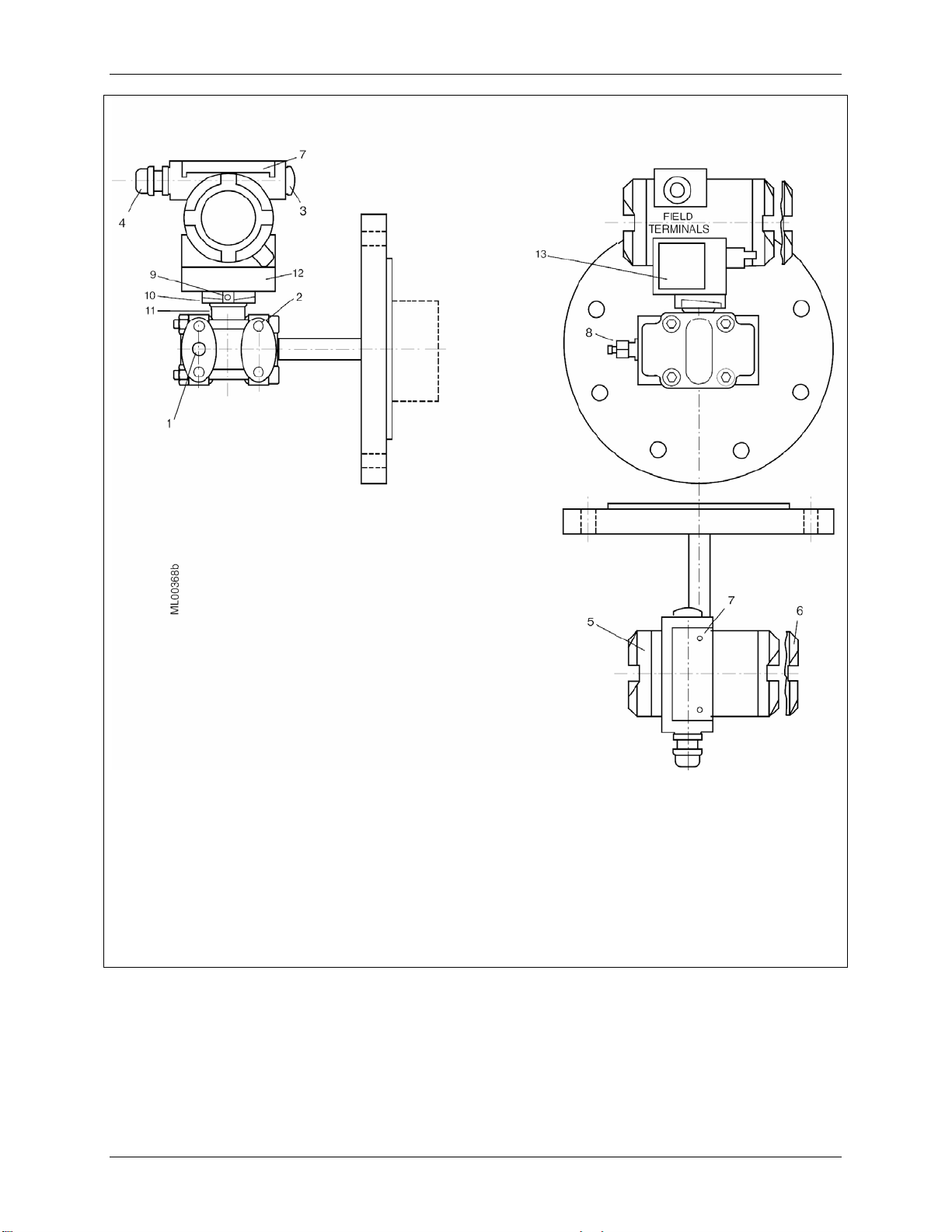
1
Process connection:
1/2-NPT, connection shank G1/2A
Oval flange
2
Blanking plug
3
Electrical connection:
Screwed gland M20 x 1.5
Screwed gland 1/2-14NPT
4
Field terminals; remove enclosure cap for
access
5
Electronics module and display; remove
enclosure cap for access
FIGURE 1-1 Gauge Construction, Pressure and Absolute Pressure Models
6
Hinged access cover over magnetic
pushbuttons
7
Mounting bracket, optional
8
Tag plate
9
Approval plate; Rating plate on other side
10
Enclosure ground screw
11
Enclosure setscrew
12
Enclosure rotation limits
13
Enclosure rotation reference arrow; see
Section 4 for details
This Figure is for Models 7MF4033 and
7MF4233
November 2005
1-3
Introduction UMSITRPDS3-1
1
Process Connection 1/4-18NPT for absolute
pressure + side
2
Mounting thread M10, M12 or 7/16-20UNF
3
Blanking plug
4
Electrical connection:
Screwed gland M20 x 1.5
Screwed gland 1/2-14NPT
5
Field terminals; remove enclosure cap for
access
6
Electronics module and display; remove
enclosure cap for access
7
Hinged access cover over magnetic
pushbuttons
8
Sealing screw
9
Side vent for measuring liquid
FIGURE 1-2 Differential Construction; Differential, Flow, and Absolute Models
10
Side vent for measuring gas (supplement H02)
11
Mounting bracket, optional
12
Enclosure setscrew
13
Enclosure rotation limits (see 14 reference
arrow)
14
Enclosure rotation reference arrow; see
Section 4 for details
15
Tag plate
16
Approval plate; Rating plate on other side
17
Enclosure ground screw
This Figure is for Models 7MF4333, 7MF4433,
and 7MF4533.
November 2005
1-4
UMSITRPDS3-1 Introduction
1
Process connection 1/4-18NPT
Mounting thread M10 or 7/16-20UMF
2
Field terminals; remove enclosure cap for
3
access
Electronics module and display; remove
4
enclosure cap for access
Sealing screw
5
Enclosure setscrew
6
Enclosure rotation limits; enclosure
7
rotation reference arrow on neck (see
Section 4 for details)
10
11
12
13
14
15
FIGURE 1-3 Differential Pressure and Flow Models with H03 Option
November 2005
Blanking plug
Access cover over magnetic pushbuttons
Electrical connection:
M20 x 1.5
1/2-14NPT
Tag plate
Approval plate; Rating plate on other side
Enclosure ground screw
This Figure is for Models 7MF4433 and
7MF4533 with H03 option.
1-5
Introduction UMSITRPDS3-1
1
Process connection at low side 1/4-18NPT
2
Mounting thread M10, M12, or 7/16-20UNF
3
Blanking plug
4
Electrical connection:
M20 x1.5
1/2-14NPT
5
Field terminals; remove enclosure cap for
access
6
Electronics module and display; remove
enclosure cap for access
7
Access cover to magnetic pushbuttons
8
Sealing screw with valve
9
Enclosure setscrew
10
Enclosure rotation limits
11
Enclosure rotation reference arrow (not
shown; see Section 4 for details)
12
Tag plate
13
Rating plate; approval plate on other side
This Figure is for Models 7MF4633 and
7MF4912
FIGURE 1-4 Flanged Liquid Level Models
November 2005
1-6
UMSITRPDS3-1 Introduction
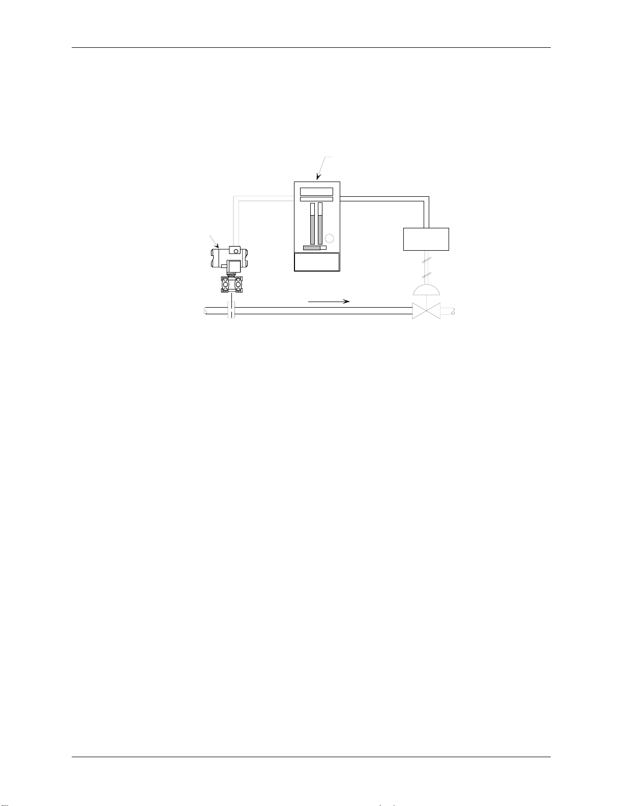
A transmitter can operate in either analog mode or digital mode, as discussed in the following paragraphs.
Analog Mode
A single transmitter is connected to a controller, recorder, or other field device. A loop known as a Pointto-Point network interconnects the instruments. Figure 1-5shows a traditional application.
Process Automation Controller
2-Wire
4-20 mA
MG00369b
I/P
Model 773
Differential
Transmitter
2-Wire
4-20 mA
Model 353
Flow
FIGURE 1-5 Traditional Application
The HART
®
(Highway Addressable Remote Transducer) protocol is used for communication between the
transmitter and a HART Communicator, a personal computer running configuration software, or another
remote device. This is done by superimposing the HART digital signal on the analog current. HART
communications can be used to transfer a new or edited configuration, remotely monitor the process
variable, or service a transmitter.
Digital Mode
Up to 15 transmitters can be parallel connected to a Multi-Drop network using only shielded, twisted-pair
cable. The HART protocol provides communication between the transmitters and a HART-compatible
controller, recorder, or other device. Each transmitter is identified by a unique network address that is
selected during configuration.
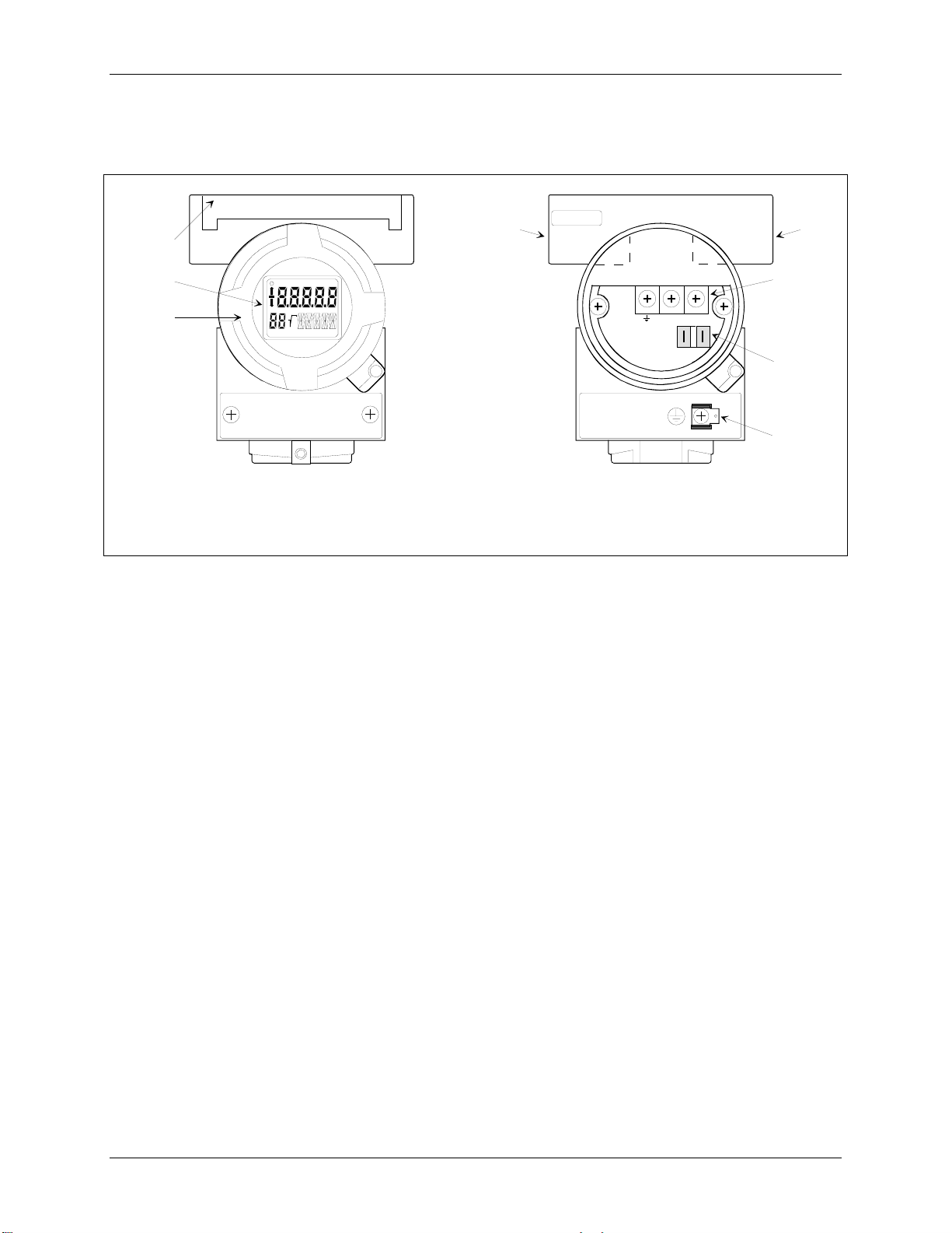
Display, Magnetic Pushbuttons, and Loop Connections
The optional display (Figure 1-6) permits local viewing of input and output variables and status messages,
and it simplifies local configuration. Local configuration is performed using three magnetic pushbuttons
that are found beneath an access cover in the transmitter housing. Section 6 On-Line Configuration and
Operation describes use of the display and magnetic pushbuttons.
Loop connections are made to a terminal assembly with three screw terminals (Figure 1-7). The assembly
is located within the transmitter enclosure and is accessed by removing the enclosure cap adjacent to
FIELD TERMINALS on the enclosure. The terminal assembly also has terminals to connect an external
digital milliammeter for loop troubleshooting and transmitter calibration. Loop wiring is shown in Section
4 Installation.
November 2005
1-7
Introduction UMSITRPDS3-1
An enclosure ground connection is located on the housing beneath the field terminal enclosure cap. The
enclosure should always be grounded by a wire connected from this terminal to an earth ground, even
when a ground may be provided by metal conduit protecting the loop wiring.
2
44
1
3
+
+
MG00364b
MG00364b
+
_
-4-20mA+
1
2
3
1
Digital display, optional
2
Magnetic pushbutton access cover
3
Enclosure cap
1
Field terminals for analog output
2
External digital milliammeter terminals
3
Enclosure ground
4
Electrical entrances; plug unused entrance
FIGURE 1-6 Display FIGURE 1-7 Field Terminals
Transmitters have an intrinsically safe, explosion proof, NEMA 4x (IP67/68), field mountable, hardened
enclosure. Electrical conduit connections are 1/2-14 NPT or M20 x 1.5. All process wetted materials are
316 stainless steel or better. The flush-mount process connection of the liquid level model is compatible
with standard ANSI and metric flange sizes for tanks and pipes.
November 2005
1-8
UMSITRPDS3-1 Introduction
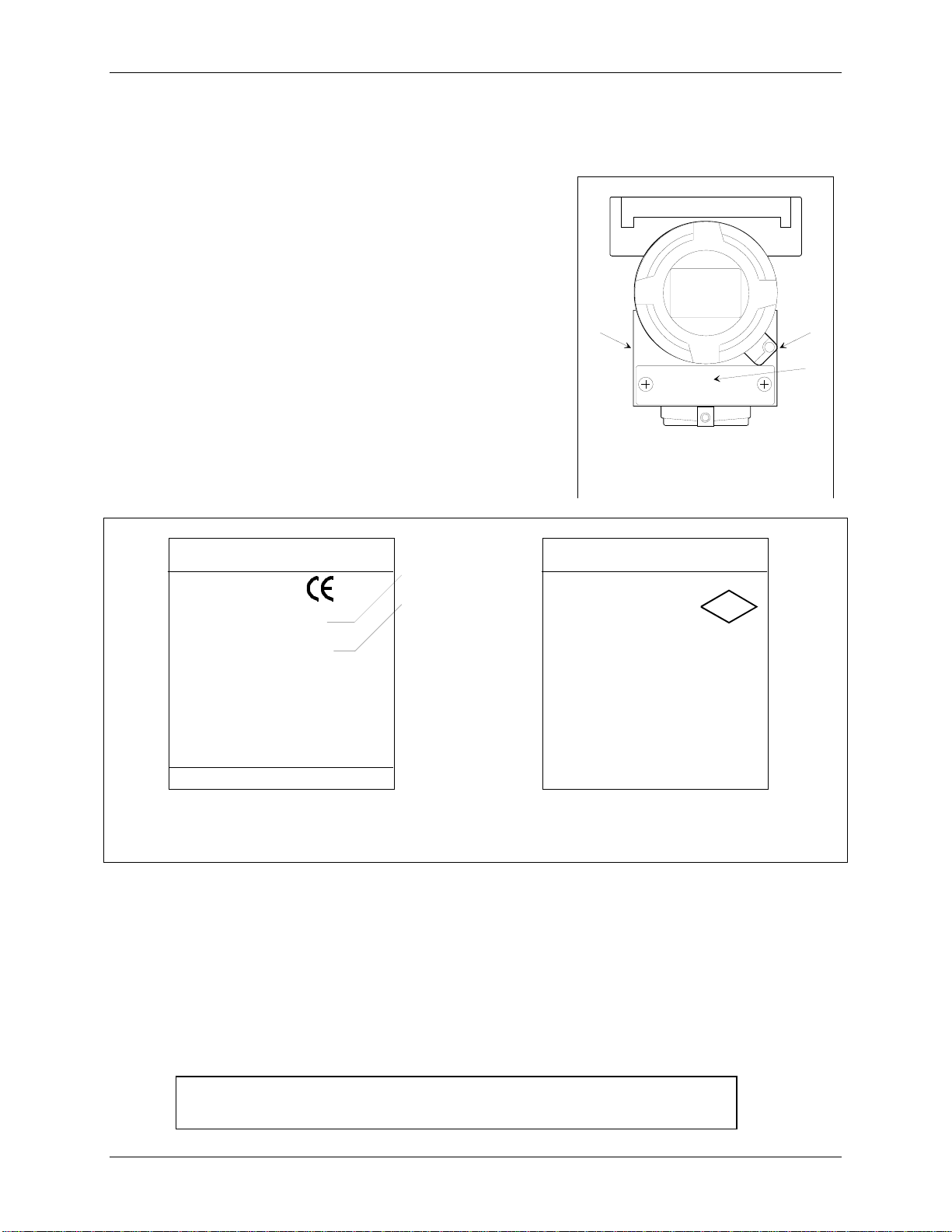
1.3 RATING, APPROVAL, AND TAG PLATES
These plates are fastened to the outside of the transmitter
enclosure, as shown at right. The rating plate shows that
transmitter’s model number, serial number, and performance
data. The approval plate shows that transmitter’s approval and
certification data. Always refer to these plates to confirm the
model number, performance data and approval and certification
data before installing or servicing a transmitter. Representative
plates are shown below.
The tag plate is fastened with two screws so it can be
removed for engraving.
SIEMENS
D-76181 Karlsruhe
SITRANS P
Transmitter for diff. pressure
7MF4433-1DA20-1HC6-Z
A01+B11+Y01
Feb. Nr. N1-M831-9292402
VH :DC 10.5-45V (not intr. safe) outp.: 4-20 mA
Mat.: Connec. Diaphr. O-ring Filling
1.4408 1.4404 FPM Siliconoil
Measuring span : 2.5 - 250 mbar
Rated pressure : PN 160
Type of protection IP 65
Made in USA
Rating Plate
1 Model number
2 Serial number
1
2
MG00384a
+
12
MG00353a
+
3
1 Rating plate
2 Approval plate
3 Tag plate
SIEMENS
D-76181 Karlsruhe
SITRANS P
(XP/DIP) or (IS)
CL I ZN 0/1 AEX ia IIC T4..T6
CL I,II,II DIV 1 ABCKEFB T4..T6
Per Control Dwg. A5E00072770A
Vi < 30V : Ii < 100 mA : Pi < 0.75 W
Ci < 6 nF : Li < 0.4 mH
(NI) CL 1 DIV 2 ABCD T4..T6
CL II DIV 2 GP FB, CL III
Vmax = 30 V
Ta - T4: - 40..85ºC ; T6: -40..60ºC
ENCL T ype 4X
FW: 11.02.03 HW: 02.05.01
Approval Plate
FM
APPROVED
MG00384a
1.4 CONFIGURATION
A transmitter must be configured before use. Each transmitter is shipped with either a default
configuration or, if specified at time of order, a custom configuration defined by the user. The default
configuration may need to be edited before the transmitter is used in a loop. The configuration is stored
within the transmitter in a non-volatile memory.
A configuration can be created or edited locally at the transmitter’s magnetic pushbuttons or remotely
using the Model 275 HART Communicator.
Note: If using a Model 375 Field Communicator, see the inside of the front
cover of this manual.
November 2005
1-9
UMSITRPDS3-1 Model 275 Universal Hart Communicator
2.0 MODEL 275 UNIVERSAL HART COMMUNICATOR
The Model 275 Universal HART Communicator is a handheld interface that provides a common
communication link to SITRANS P transmitters and other HART-compatible instruments.
This section describes HART Communicator connections, liquid crystal display, keypad, and on-line and
off-line menus. It also provides overviews of many Communicator functions. The Communicator is
shown in Figure 2-1. For information about the Communicator’s battery pack, Memory Module, Data
Pack, and maintenance procedures, refer to the manual supplied with the Communicator.
2.1 INTRODUCTION
The HART Communicator connects to and communicates with a transmitter or other HART device using
a 4-20 mA loop, provided a minimum load resistance of 250Ω is present between the Communicator and
the power supply. The Communicator uses Bell 202 frequency-shift keying (FSK) to impose highfrequency digital signals on a standard 4-20 mA current loop. Because no net energy is added to the loop,
HART communication does not disturb the 4-20 mA signal.
The Communicator can be used in hazardous and non-hazardous locations.
WARNING
Explosion can cause death or serious injury.
Before connecting the HART Communicator in an
explosive atmosphere, be sure that the instruments in
the loop are installed in accordance with intrinsically
safe or non-incendive field wiring practices.
Refer to the Communicator nameplate and the supplied
manual for certifications and approvals before
connecting, or making a connection to the serial port or
NiCad charger port on the Communicator.
2.2 COMMUNICATOR CONNECTIONS
The Communicator can interface with a transmitter from the control room, the instrument site, or any
wiring termination point in the loop. Connections are made through a supplied 40" (1m) cable (dual
banana plug to mini-hook test clips). The connection panel also may have a jack for the optional NiCad
charger, and it has a serial port for a future connection to a personal computer (PC).
To interface with a transmitter or other HART device, connect the HART Communicator in parallel with
the instrument or load resistor. The connections are non-polar. For intrinsically safe FM and CSA wiring
connections, see the manual supplied with the Communicator.
Figure 2-2 illustrates typical wiring connections between the HART Communicator and a loop with a
transmitter or other HART-compatible device in a loop. The Communicator is quickly connected into a
transmitter loop.
November 2005
2-1
Model 275 Universal Hart Communicator UMSITRPDS3-1
9
10
11
12
1
2
7
F1 F2 F3 F4
3
HART Communicator
4
5
6
MG00360a
I
O
A B C D E F G H I
13
2
J K L
8
M N O P Q R
4
5
V W X Y Z /
S T U
78
# % &
< >
.
0
6
9
+
:
*
_
Model 275 Universal HART Communicator
1
Liquid Crystal Display (LCD), 8 lines, 21 characters per line
2
Function Keys (softkeys), software defined
3
Action Keys – ON/OFF (I/O), Up Arrow, Quick Access Key (>>>), Previous Menu (Back, left arrow),
4
Down Arrow, Select (Forward, right arrow)
Alphanumeric Keys (keypad number sequence may be different from that shown)
5
Shift Keys – Use to select alphabetic and other characters above a number, period, or dash.
6
Communicator Nameplate – On back of device. See nameplate for certifications and approvals
7
before connecting in a hazardous location.
Communicator model number and serial number on back
8
Connection panel.
9
Non-polar loop connection; dual banana plug
10
Serial port for PC connection; DB9
11
NiCad Charger Jack, optional
12
FIGURE 2-1 Model 275 Universal HART Communicator
Note: If using a Model 375 Field Communicator, see the
inside of the front cover of this manual.
November 2005
2-2
UMSITRPDS3-1 Model 275 Universal Hart Communicator
Range Resistor
250, typical
Controller,
Recorder, or
Other 1-5 Vdc
Device; See
Note 2
I
Current Sense
Resistor 250 to
1100; See Note 3
+
_
O
See
Note 1
Circuit
Junction
MG00359a
Non-Hazardous
Location
Hazardous
Location
Transmitter
Terminals
_
+
- +
4-20 mA
See Note 4
IOI
O
I
O
I
See
O
Note 1
Notes:
1 HART Communicator Connections:
Non-hazardous location – Connect as shown above.
Hazardous location – Refer to Communicator nameplate and the manual supplied with the
Communicator for certifications and approvals before connecting.
The HART Communicator is a non-polar device.
2 The System Power Supply may be part of the host input device or a separate device.
3 Network resistance equals the sum of the barrier resistances and the current sense resistor.
Minimum value is 250; maximum value is 1100.
4 Supply and return barriers are shown. Interconnect all cable shields and ground only at the barriers.
FIGURE 2-2 HART Communicator Connections to a Transmitter Loop
November 2005
2-3

Model 275 Universal Hart Communicator UMSITRPDS3-1
2.3 CONTROLS OVERVIEW
As shown in Figure 2-1, the front of the HART Communicator has five major functional areas: liquid
crystal display (LCD), function keys, action keys, alphanumeric keys, and shift keys. The next five
sections describe how each of these functional areas is used to enter commands and display data.
2.3.1 Liquid Crystal Display
The liquid crystal display (LCD) is an 8-line by 21-character display that provides communication
between the user and a connected device. When the HART Communicator is connected to a SITRANS P
transmitter or other HART-compatible device, the top line of the Online menu displays the model name
of the device and its tag. A typical display is shown below. The actual display content can vary with the
device type and manufacturer.
SITRANS P
Online
1->Pres
2 Type
3 Device setup
HELP |SAVE
Note: If using a Model 375 Field
Communicator, see the inside of
the front cover of this manual.
The bottom line of each menu is reserved for dynamic labels for the software-defined function keys, F1F4, which are found directly below the display. More information on software-defined function keys is
given in the next section.
2.3.2 Software-Defined Function Keys
The four software-defined function keys (softkeys), located below the LCD and marked F1 through F4,
are used to perform software functions as indicated by the dynamic labels. Pressing the function key
immediately beneath a label activates the displayed function.
The label appearing above a function key indicates the function of that key for the current menu
. For
example, in menus providing access to on-line help, the HELP label appears above the F1 key. In menus
providing access to the Online menu, the HOME label appears above the F3 key. Table 2-1 lists these
labels and describes what happens when each function key is pressed.
November 2005
2-4

UMSITRPDS3-1 Model 275 Universal Hart Communicator
TABLE 2-1 Function Keys with Their Labels and Actions Performed
F1 F2 F3 F4
HELP
Access on-line help
RETRY
Try to reestablish
communication
EXIT
Leave the current menu
YES
Answer to yes/no
question
ALL
Include current Quick
Access Key item on
Quick Access Key
menu for all devices
ON/OFF
Activate or deactivate a
bit-enumerated binary
variable
DEL
Delete current
character or Quick
Access Key menu item
SEND
Send configuration
data to device
PGUP
Move up one help
screen
PREV
Go to previous
message in a list of
messages
ABORT
Terminate current task
ESC
Leave a value
unchanged
QUIT
Terminate session
because of a
communication error
PGDN
Move down one help
screen
NEXT
Go to next message in
a list of messages
OK
Acknowledge
information on the
LCD
ENTER
Accept user-entered
data
EXIT
Leave the current menu
NO
Answer to yes/no
question
ONE
Include Quick Access
Key item for one
device
NEXT
Go to the next variable
in off-line edit
FILTR
Open customization
menu to sort
configurations
XPAND
CMPRS
SAVE
Save information to
Communicator
MARK
Toggle marked
variable in
configuration to be sent
to a field device
Opens detailed
configuration
information
Closes detailed
configuration
information
HOME
Go the top menu in the
device description
BACK
Go back to the menu
from which HOME
was pressed
EDIT
Edit a variable value
ADD
Add current item to
Quick Access Key
menu
November 2005
2-5

Model 275 Universal Hart Communicator UMSITRPDS3-1
2.3.3 Action Keys
Directly beneath the LCD and software-defined function keys are six blue, white, and black action keys.
Each has a specific function as described below:
I
ON/OFF KEY – Use to power-up the Communicator. When the Communicator is turned on,
it automatically searches for a HART-compatible device on the 4-20 mA loop. If no device is
O
found, the Communicator displays the Main menu:
If a SITRANS P transmitter is found, the Communicator displays the Online menu:
UP ARROW KEY – Use to move the cursor up through a menu or list of options or to scroll
through lists of available characters when editing fields that accept both alpha and numeric
data.
DOWN ARROW KEY – Use to move the cursor through a menu or a list of options or to
scroll through lists of available characters when editing fields that accept alpha and numeric
data.
LEFT ARROW/PREVIOUS MENU KEY – Use to move the cursor to the left or back to the
previous menu.
HART Communicator
1Offline
2 Online
3 Frequency device
4 Utility
SITRANS P
Online
1Pres
2 Type
3 Device setup
HELP |SAVE
RIGHT ARROW/SELECT KEY – Use to move the cursor to the right or to select a menu
option.
QUICK ACCESS KEY (HOT KEY) – When the Communicator is on and connected to a
HART-compatible device, pressing the Quick Access Key instantly displays the Quick Access
Key menu of user-defined options. When the Communicator is off and the Quick Access Key
is pressed, the Communicator automatically powers-up and displays the Quick Access Key
menu.
See Section 2.6 for more information on using the Quick Access Key.
November 2005
2-6

UMSITRPDS3-1 Model 275 Universal Hart Communicator
Important
When performing certain operations, the message “OFF KEY DISABLED”
indicates that the Communicator cannot be turned off. This feature helps prevent
accidental shutoff of the Communicator while the output of a device is fixed or a
device variable is being edited.
2.3.4 Alphanumeric and Shift Keys
The alphanumeric keys perform two functions: (1) rapid selection of menu options and (2) data entry. The
shift keys located below the alphanumeric keys on the keypad are used during data entry to select from
among the characters available above each number.
2.3.4.1 Rapid Selection of Menu Options
From any menu, use the keypad to select available options in two ways. First, use the UP or DOWN
arrow keys, followed by the RIGHT ARROW/SELECT key, to access available options displayed on the
LCD.
As an alternative, use the rapid select feature. Simply press the number on the alphanumeric keypad that
corresponds to the desired menu option. For example, to quickly access the Utility menu from the Main
menu, simply press “4” on the keypad.
2.3.4.2 Data Entry
Some menus require data entry. Use the alphanumeric and shift keys to enter all alphanumeric
information into the HART Communicator. Pressing an alphanumeric key alone while editing causes the
large character in the center of the key (number 0-9, decimal point, or dash) to be entered.
Pressing and releasing a shift key activates shift and causes the appropriate arrow icon (, , or ) to
appear in the upper right-hand corner of the LCD. When shift is activated, the indicated alpha characters
or symbols are entered when the keypad is used.
Example
To enter a number, such as “7,” simply press the number key.
To enter one of the small characters appearing above the large numeral (i.e., a letter, space, or
mathematical symbol), first press and release
the corresponding shift key at the bottom of the keypad,
then press the desired alphanumeric key. To enter the letter “E,” press and release the middle shift key,
then press the number “2” key.
To deactivate a shift key without entering a letter, space, or mathematical symbol, simply press that shift
key again.
November 2005
2-7
Model 275 Universal Hart Communicator UMSITRPDS3-1
A
2.4 GETTING TO KNOW THE COMMUNICATOR
The HART Communicator operates either on-line or off-line. Off-line operation is used to create or edit a
configuration that can then be downloaded to a HART device, such as a transmitter. On-line operation is
used to download a configuration to a HART device, upload a configuration, edit HART device operating
parameters, and monitor process values.
For off-line operation, the Communicator need not be connected to a HART device. On-line operation
requires a connection to a powered HART device.
The menu that appears first when the Communicator is turned on depends on whether the Communicator
is connected to a powered HART device.
• Communicator not connected - Main menu (off-line operation)
• Communicator connected - Online menu (on-line operation)
To work off-line when connected to a powered loop, access the Main menu from the Online menu by
pressing the LEFT ARROW/PREVIOUS MENU key.
Note
Communicator internal operation is controlled by firmware. Consequently,
operation will depend upon the firmware version and the installed device drivers,
as discussed in this section.
2.4.1 Display Icons
Several different symbols (icons) appear on the LCD to show the state of the Communicator and provide
visible response to actions of the user. Figure 2-3 shows the display icons and how they relate to keypad
functions.
HART Communication
( indicates connected
device is configured in
the burst mode)
ccess Additional
Menu Items
HART Communicator
Device Info
2 Dev Type
3 Dev ID 0
4 Tag
5 MM/DD/YY 10/10/10
6 Write Protect Yes
Low Battery
Access
Previous
Menu
X03034S1
FIGURE 2-3 HART Communicator Display Icons
November 2005
2-8

UMSITRPDS3-1 Model 275 Universal Hart Communicator
2.4.2 Menu Structure
The HART Communicator uses a hierarchical menu structure. That is, high-level menus are accessed
first, and they provide access to lower-level menus. This structure groups related functions together and
minimizes the number of options displayed at once.
To become familiar with the menu structure, perform the following actions:
1. With the Communicator off-line (not attached
to any devices), press the ON/OFF key to turn the
Communicator on. The Communicator will perform a self-test routine and display the firmware
revision level installed in the Communicator. It will then display a “Polling?” query. Press NO (F4) to
go to the Main menu.
2. The cursor () will be positioned at “1 Offline” on the Main menu. Access the Utility menu by
pressing the DOWN arrow key three times, then pressing the RIGHT ARROW/SELECT key. The
display changes to show the Utility menu.
3. Access the Configure Communicator menu from the Utility menu by pressing the RIGHT
ARROW/SELECT key. The display changes to show the Configure Communicator menu.
4. Access the Contrast menu by pressing the DOWN arrow once, then pressing the RIGHT
ARROW/SELECT key. The display shows a message explaining how to adjust the LCD contrast.
5. Press ESC (F3) to return to the Configure Communicator menu.
6. Press the LEFT ARROW/PREVIOUS MENU key two times to return to the Main menu.
7. Press the ON/OFF key to turn the Communicator off.
2.4.3 Reviewing Installed Devices
For the HART Communicator to recognize a specific HART-compatible device, it must contain a
description for that device. Communicator device descriptions for Moore and Siemens products are listed
in Table 2-2. Device descriptions for many other HART-compatible devices from leading manufacturers
are included but not listed in the table.
Communicator firmware also contains a “generic” device description, which allows limited access to most
HART devices when no device description for that specific product is included.
To review the currently installed device descriptions:
1. Turn on the Communicator (off-line) to display the Main Menu.
2. In the Main menu, press “4 Utility” on the keypad.
3. In the Utility menu, press “5 Simulation” on the keypad. The LCD shows the Manufacturer menu,
which contains a list of manufacturers whose device descriptions are installed in the Communicator.
4. Press the DOWN arrow to highlight SIEMENS (or other manufacturer). Press the RIGHT
ARROW/SELECT key to reveal the Model menu, which lists the device descriptions currently
installed in the Communicator (see Table 2-2).
5. To end the review of devices, press the LEFT ARROW/PREVIOUS MENU key three times.
6. Turn off the Communicator or proceed to the next section.
November 2005
2-9
 Loading...