


SHARP LC-40LE814E, LC-46LE814E, LC-40LE824E, LC-46LE824E, LC-40LE814RU Service Manual
...LC-40/46LE814/824E/RU (1st Edition)
SERVICE MANUAL
No. S90K840LE814E
LCD COLOUR TELEVISION
LC-40LE814E/RU
LC-46LE814E/RU
LC-40LE824E/RU
MODELS LC-46LE824E/RU
In the interests of user-safety (Required by safety regulations in some countries) the set should be restored to its original condition and only parts identical to those specified should be used.
OUTLINE
This Service Manual covers the differences from LC-40/46LE810E and LC-40/46LE820E.
For other technical information, refer to the LC-40/46LE810E, LC-40/46LX810E (No. S30E940LE810E) Service Manual and LC-40/46/52LE820E, LC-40/46LU820E (No. S30F240LE820E) Service Manual.
CONTENTS
OUTLINE AND DIFFERENCES FROM BASE MODEL |
|
|
|
OUTLINE.................................................................... |
i |
|
DIFFERENCES FROM BASE MODEL |
|
|
(LC-40LE814E/RU) .................................................... |
i |
|
DIFFERENCES FROM BASE MODEL |
|
|
(LC-46LE814E/RU) .................................................... |
i |
|
DIFFERENCES FROM BASE MODEL |
|
|
(LC-40LE824E/RU) ................................................... |
ii |
|
DIFFERENCES FROM BASE MODEL |
|
|
(LC-46LE824E/RU) ................................................... |
ii |
SAFETY PRECAUTION |
|
|
|
IMPORTANT SERVICE SAFETY |
|
|
PRECAUTION........................................................... |
iii |
|
Precautions for using lead-free solder ..................... |
iv |
|
End of life disposal .................................................... |
v |
OUTLINE |
|
|
|
MAJOR SERVICE PARTS ....................................... |
vi |
CHAPTER 1. SPECIFICATIONS |
1-1 |
|
[1] |
SPECIFICATIONS ................................................. |
|
CHAPTER 2. OPERATION MANUAL |
2-1 |
|
[1] |
OPERATION MANUAL .......................................... |
|
CHAPTER 3. DIMENSIONS |
3-1 |
|
[1] |
DIMENSIONS ........................................................ |
|
CHAPTER 4. ADJUSTMENT |
4-1 |
|
[1] |
ADJUSTMENT PROCEDURE ............................... |
|
CHAPTER 5. TROUBLESHOOTING TABLE |
5-1 |
[1] TROUBLESHOOTING TABLE............................... |
[2]LED flashing specification at the time of the error...5-14
CHAPTER 6. MAJOR IC INFORMATIONS |
6-1 |
[1] MAJOR IC INFORMATIONS.................................. |
CHAPTER 7. OVERALL WIRING/BLOCK DIAGRAM
[1]OVERALL WIRING DIAGRAM
(LC-40LE814E/RU) ................................................ |
7-1 |
[2]OVERALL WIRING DIAGRAM
(LC-46LE814E/RU) ................................................ |
7-2 |
[3]OVERALL WIRING DIAGRAM
(LC-40LE824E/RU) ................................................ |
7-3 |
[4]OVERALL WIRING DIAGRAM
(LC-46LE824E/RU) ................................................ |
7-4 |
[5]SYSTEM BLOCK DIAGRAM
(LC-40LE814E/RU)(LC-46LE814E/RU).................7-5
[6]SYSTEM BLOCK DIAGRAM
(LC-40LE824E/RU)(LC-46LE824E/RU).................7-6
Parts Guide
Parts marked with "  " are important for maintaining the safety of the set. Be sure to replace these parts with specified ones for maintaining the safety and performance of the set.
This document has been published to be used for after sales service only.
The contents are subject to change without notice.

LC-40/46LE814/824E/RU (1st Edition)
OUTLINE AND DIFFERENCES FROM BASE MODEL
OUTLINE
This Service Manual covers the differences from LC-40/46LE810E and LC-40/46LE820E.
For other technical information, refer to the LC-40/46LE810E, LC-40/46LX810E (No. S30E940LE810E) Service Manual and LC-40/46/52LE820E, LC-40/46LU820E (No. S30F240LE820E) Service Manual.
DIFFERENCES FROM BASE MODEL (LC-40LE814E/RU)
Ref No. |
Description |
|
LC-40LE810E |
LC-40LE814E/RU |
Interchangeability |
Note |
|
(No. S30E940LE810E) |
(No. S90K840LE814E) |
||||
|
|
|
|
|
||
PRINTED WIRING BOARD ASSEMBLIES |
|
|
|
|
||
N |
MAIN Unit |
|
DKEYDF455FM03 |
DKEYDF455FM11 |
|
Changed |
N |
ICON Unit |
|
DUNTKF493FM03 |
← |
— |
No change |
N |
R/C, LED Unit |
|
DUNTKF494FM02 |
← |
— |
No change |
N |
POWER/LED CONTROL Unit |
|
RUNTKA685WJQZ |
← |
— |
No change |
N |
TOUCH SENSOR Unit |
|
RUNTKA692WJQZ |
← |
— |
No change |
N |
LCD CONTROL Unit |
|
RUNTK4512TPZC |
← |
— |
No change |
|
|
|
|
|
|
|
LCD PANEL MODULE |
|
|
|
|
||
N |
40” LCD Panel Module Unit |
|
R1LK400D3LWF2Y |
← |
— |
No change |
|
|
|
|
|
|
|
CABINET PARTS |
|
|
|
|
||
Please refer to a Parts Guide |
|
|
|
|
||
|
|
|
|
|
||
SUPPLIED ACCESSORIES |
|
|
|
|
||
Please refer to a Parts Guide |
|
|
|
|
||
|
|
|
|
|
||
PACKING PARTS (NOT REPLACEMENT ITEM) |
|
|
|
|
||
Please refer to a Parts Guide |
|
|
|
|
||
|
|
|
|
|
||
SERVICE JIGS (USE FOR SERVICING) |
|
|
|
|
||
Please refer to a Parts Guide |
|
|
|
|
||
DIFFERENCES FROM BASE MODEL (LC-46LE814E/RU) |
|
|
||||
Ref No. |
Description |
LC-46LE810E |
LC-46LE814E/RU |
Interchangeability |
Note |
|
(No. S30E940LE810E) |
(No. S90K840LE814E) |
|||||
|
|
|
|
|||
PRINTED WIRING BOARD ASSEMBLIES |
|
|
|
|
||
N |
MAIN Unit |
DKEYDF455FM03 |
DKEYDF455FM11 |
|
Changed |
|
N |
ICON Unit |
DUNTKF493FM03 |
← |
— |
No change |
|
N |
R/C, LED Unit |
DUNTKF494FM02 |
← |
— |
No change |
|
N |
POWER/LED CONTROL Unit |
RUNTKA686WJQZ |
← |
— |
No change |
|
N |
TOUCH SENSOR Unit |
RUNTKA692WJQZ |
← |
— |
No change |
|
N |
LCD CONTROL Unit |
RUNTK4437TPZE |
RUNTK4512TPZC |
|
Changed |
|
|
|
|
|
|
|
|
LCD PANEL MODULE |
|
|
|
|
||
N |
46” LCD Panel Module Unit |
R1LK460D3LWA2Y |
R1LK460D3LWG2Y |
|
Changed |
|
|
|
|
|
|
|
|
CABINET PARTS
Please refer to a Parts Guide
SUPPLIED ACCESSORIES
Please refer to a Parts Guide
PACKING PARTS (NOT REPLACEMENT ITEM)
Please refer to a Parts Guide
SERVICE JIGS (USE FOR SERVICING)
Please refer to a Parts Guide
i

LC-40/46LE814/824E/RU (1st Edition)
DIFFERENCES FROM BASE MODEL (LC-40LE824E/RU)
Ref No. |
Description |
|
LC-40LE820E |
LC-40LE824E/RU |
Interchangeability |
Note |
|
(No. S30F240LE820E) |
(No. S90K840LE814E) |
||||
|
|
|
|
|
||
PRINTED WIRING BOARD ASSEMBLIES |
|
|
|
|
||
N |
MAIN Unit |
|
DKEYDF455FM01 |
DKEYDF455FM12 |
|
Changed |
N |
ICON Unit |
|
DUNTKF493FM03 |
← |
— |
No change |
N |
LOGO Unit |
|
DUNTKF493FM04 |
← |
— |
No change |
N |
R/C, LED Unit |
|
DUNTKF494FM02 |
← |
— |
No change |
N |
POWER/LED CONTROL Unit |
|
RUNTKA685WJQZ |
← |
— |
No change |
N |
TOUCH SENSOR Unit |
|
RUNTKA690WJQZ |
RUNTKA761WJQZ |
|
Changed |
N |
LCD CONTROL Unit |
|
RUNTK4512TPZC |
← |
— |
No change |
|
|
|
|
|
|
|
LCD PANEL MODULE |
|
|
|
|
||
N |
40” LCD Panel Module Unit |
|
R1LK400D3LWF0Y |
← |
— |
No change |
|
|
|
|
|
|
|
CABINET PARTS |
|
|
|
|
||
Please refer to a Parts Guide |
|
|
|
|
||
|
|
|
|
|
||
SUPPLIED ACCESSORIES |
|
|
|
|
||
Please refer to a Parts Guide |
|
|
|
|
||
|
|
|
|
|
||
PACKING PARTS (NOT REPLACEMENT ITEM) |
|
|
|
|
||
Please refer to a Parts Guide |
|
|
|
|
||
|
|
|
|
|
||
SERVICE JIGS (USE FOR SERVICING) |
|
|
|
|
||
Please refer to a Parts Guide |
|
|
|
|
||
DIFFERENCES FROM BASE MODEL (LC-46LE824E/RU) |
|
|
||||
Ref No. |
Description |
LC-46LE820E |
LC-46LE824E/RU |
Interchangeability |
Note |
|
(No. S30F240LE820E) |
(No. S90K840LE814E) |
|||||
|
|
|
|
|||
PRINTED WIRING BOARD ASSEMBLIES |
|
|
|
|
||
N |
MAIN Unit |
DKEYDF455FM01 |
DKEYDF455FM12 |
|
Changed |
|
N |
ICON Unit |
DUNTKF493FM03 |
← |
— |
No change |
|
N |
LOGO Unit |
DUNTKF493FM04 |
← |
— |
No change |
|
N |
R/C, LED Unit |
DUNTKF494FM02 |
← |
— |
No change |
|
N |
POWER/LED CONTROL Unit |
RUNTKA686WJQZ |
← |
— |
No change |
|
N |
TOUCH SENSOR Unit |
RUNTKA690WJQZ |
RUNTKA761WJQZ |
|
Changed |
|
N |
LCD CONTROL Unit |
RUNTK4437TPZE |
RUNTK4512TPZC |
|
Changed |
|
|
|
|
|
|
|
|
LCD PANEL MODULE |
|
|
|
|
||
N |
46” LCD Panel Module Unit |
R1LK460D3LWA0Y |
R1LK460D3LWG0Y |
|
Changed |
|
|
|
|
|
|
|
|
CABINET PARTS
Please refer to a Parts Guide
SUPPLIED ACCESSORIES
Please refer to a Parts Guide
PACKING PARTS (NOT REPLACEMENT ITEM)
Please refer to a Parts Guide
SERVICE JIGS (USE FOR SERVICING)
Please refer to a Parts Guide
Interchangeability
|
|
|
|
|
|
Interchangeable from |
|
|
|
|
|
A: |
Completely interchangeable |
OLD |
= |
NEW |
|
C: |
NEW |
|
OLD |
|
|
|
|
|
|
|
|
|
NEW to OLD |
|
|
|
|
|
|
|
|
|
|
|
|
|
|
|
|
|
Interchangeable from |
|
|
|
|
|
|
|
|
|
|
B: |
OLD |
|
NEW |
|
D: |
Not interchangeable |
NEW |
X |
OLD |
|
|
|
OLD to NEW |
|
|
|
|
|
|
|
|
|
|
|
|
|
|
|
|
|
|
|
|
|
|
ii
LC-40/46LE814/824E/RU (1st Edition)
SAFETY PRECAUTION
IMPORTANT SERVICE SAFETY PRECAUTION
Service work should be performed only by qualified service technicians who are thoroughly familiar with all safety checks and the servicing guidelines which follow:
WARNING
1.For continued safety, no modification of any circuit should be attempted.
2.Disconnect AC power before servicing.
CAUTION:
FOR CONTINUED PROTECTION AGAINST A RISK OF FIRE REPLACE ONLY WITH SAME TYPE FUSE.
40 inch model: F7000, F7001 (3.15A/250V)
46 inch model: F7000, F7001 (5A/250V)
BEFORE RETURNING THE RECEIVER
(Fire & Shock Hazard)
Before returning the receiver to the user, perform the following safety checks:
3.Inspect all lead dress to make certain that leads are not pinched, and check that hardware is not lodged between the chassis and other metal parts in the receiver.
4.Inspect all protective devices such as non-metallic control knobs, insulation materials, cabinet backs, adjustment and compartment covers or shields, isolation resistor-capacitor networks, mechanical insulators, etc.
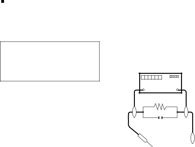
5.To be sure that no shock hazard exists, check for leakage current in the following manner.
•Use an AC voltmeter having with 5000 ohm per volt, or higher, sensitivity or measure the AC voltage drop across the resistor.
•Connect the resistor connection to all exposed metal parts having a return to the chassis (antenna, metal cabinet, screw heads, knobs and control shafts, escutcheon, etc.) and measure the AC voltage drop across the resistor.
All checks must be repeated with the AC cord plug connection reversed. (If necessary, a nonpolarized adaptor plug must be used only for the purpose of completing these checks.)
Any reading of 1.05 V peak (this corresponds to 0.7 mA peak AC.) or more is excessive and indicates a potential shock hazard which must be corrected before returning the monitor to the owner.
DVM
AC SCALE
1.5k ohm
10W
0.15 µF
TEST PROBE
•Plug the AC cord directly into a 220~240 volt AC outlet.
•Using two clip leads, connect a 1.5k ohm, 10 watt resistor paralleled by a 0.15µF capacitor in series with all exposed metal cabinet parts and a known earth ground, such as electrical conduit or electrical ground connected to an earth ground.
TO EXPOSED |
CONNECT TO |
METAL PARTS |
KNOWN EARTH |
|
GROUND |
///////////////////////////////////////////////////////////////////////////////////////////////////////////////////////////////////////////////////////////////////////////////////////////////////////////////////////////////////////////
SAFETY NOTICE
Many electrical and mechanical parts in LCD colour television have special safety-related characteristics.
These characteristics are often not evident from visual inspection, nor can protection afforded by them be necessarily increased by using replacement components rated for higher voltage, wattage, etc.
Replacement parts which have these special safety characteristics are identified in this manual; electrical components having such features
are identified by “ ” and shaded areas in the Replacement Parts List and Schematic Diagrams.
For continued protection, replacement parts must be identical to those used in the original circuit.
The use of a substitute replacement parts which do not have the same safety characteristics as the factory recommended replacement parts shown in this service manual, may create shock, fire or other hazards.
///////////////////////////////////////////////////////////////////////////////////////////////////////////////////////////////////////////////////////////////////////////////////////////////////////////////////////////////////////////
iii
LC-40/46LE814/824E/RU (1st Edition)
Precautions for using lead-free solder
Employing lead-free solder
•“PWBs” of this model employs lead-free solder. The LF symbol indicates lead-free solder, and is attached on the PWBs and service manuals. The alphabetical character following LF shows the type of lead-free solder.
Example:
L |
F |
a |
L |
F |
a/a |
||||
|
|
|
|
|
|
|
|
|
|
Indicates lead-free solder of tin, silver and copper.
Indicates lead-free solder of tin, silver and copper.
Using lead-free wire solder
•When fixing the PWB soldered with the lead-free solder, apply lead-free wire solder. Repairing with conventional lead wire solder may cause damage or accident due to cracks.
As the melting point of lead-free solder (Sn-Ag-Cu) is higher than the lead wire solder by 40 °C, we recommend you to use a dedicated soldering bit, if you are not familiar with how to obtain lead-free wire solder or soldering bit, contact our service station or service branch in your area.
Soldering
•As the melting point of lead-free solder (Sn-Ag-Cu) is about 220 °C which is higher than the conventional lead solder by 40 °C, and as it has poor solder wettability, you may be apt to keep the soldering bit in contact with the PWB for extended period of time. However, Since the land may be peeled off or the maximum heat-resistance temperature of parts may be exceeded, remove the bit from the PWB as soon as you confirm the steady soldering condition.
Lead-free solder contains more tin, and the end of the soldering bit may be easily corroded. Make sure to turn on and off the power of the bit as required.
If a different type of solder stays on the tip of the soldering bit, it is alloyed with lead-free solder. Clean the bit after every use of it. When the tip of the soldering bit is blackened during use, file it with steel wool or fine sandpaper.
•Be careful when replacing parts with polarity indication on the PWB silk.
Lead-free wire solder for servicing
Part No. |
|
|
Description |
Code |
|
ZHNDAi123250E |
J |
φ0.3mm 250g |
(1roll) |
BL |
|
ZHNDAi126500E |
J |
φ0.6mm |
500g |
(1roll) |
BK |
ZHNDAi12801KE |
J |
φ1.0mm |
1kg (1roll) |
BM |
|
iv

LC-40/46LE814/824E/RU (1st Edition)
End of life disposal
End of life disposal
v
LC-40/46LE814/824E/RU (1st Edition)
OUTLINE
MAJOR SERVICE PARTS
PWB UNIT
Ref No. |
Parts Code |
Description |
N |
DKEYDF455FM11 |
MAIN Unit (LC-40LE814E/RU)(LC-46LE814E/RU) (*1) |
N |
DKEYDF455FM12 |
MAIN Unit (LC-40LE824E/RU)(LC-46LE824E/RU) (*1) |
N |
DUNTKF493FM03 |
ICON Unit |
N |
DUNTKF493FM04 |
LOGO Unit (LC-40LE824E/RU)(LC-46LE824E/RU) |
N |
DUNTKF494FM02 |
R/C, LED Unit |
N |
RUNTKA685WJQZ |
POWER/LED CONTROL Unit (LC-40LE814E/RU)(LC-40LE824E/RU) |
N |
RUNTKA686WJQZ |
POWER/LED CONTROL Unit (LC-46LE814E/RU)(LC-46LE824E/RU) |
N |
RUNTKA692WJQZ |
TOUCH SENSOR Unit (LC-40LE814E/RU)(LC-46LE814E/RU) |
N |
RUNTKA761WJQZ |
TOUCH SENSOR Unit (LC-40LE824E/RU)(LC-46LE824E/RU) (*2) |
N |
RUNTK4512TPZC |
LCD CONTROL Unit |
|
|
|
NOTE: (*1) Replace MAIN Unit (DKEYDF455FM11, DKEYDF455FM12) in case of IC8401 or IC3302 failure.
(*2) TOUCH SENSOR Unit (RUNTKA761WJQZ) reuse will be impossible, once it is stuck on front cabinet and exfoliates.
Therefore, please exchange of a TOUCH SENSOR Unit in the case of front cabinet exchange.
OTHER UNIT
Ref No. |
Parts Code |
Description |
|
N |
R1LK400D3LWF2Y |
40" LCD Panel Module Unit (LC-40LE814E/RU) |
|
N |
R1LK460D3LWG2Y |
46" LCD Panel Module Unit (LC-46LE814E/RU) |
|
N |
R1LK400D3LWF0Y |
40" LCD Panel Module Unit (LC-40LE824E/RU) |
|
N |
R1LK460D3LWG0Y |
46" LCD Panel Module Unit (LC-46LE824E/RU) |
|
IC FOR EXCLUSIVE USE OF THE SERVICE |
|
||
|
|
|
|
Ref No. |
Parts Code |
Description |
Q’ty |
IC501 |
RH-iXD108WJQZS |
IC (EDID for PC) |
1 |
IC2002 |
RH-iXC786WJNJQ |
IC (Monitor MICON) |
1 |
SERVICE JIGS |
|
|
|
|
|
|
|
Ref No. |
Parts Code |
Description |
Q’ty |
N |
QCNW-G616WJQZ |
Main Unit to LCD Control Unit (LW) |
1 |
N |
QCNW-G625WJQZ |
Main Unit to Power Unit (PL) |
1 |
N |
QCNW-H184WJQZ |
Main Unit to Power Unit (PD) |
1 |
N |
QCNW-H185WJQZ |
Main Unit to Power Unit (LB) |
1 |
N |
QCNW-K594WJQZ |
Main Unit to R/C, LED Unit (RA) |
1 |
N |
QCNW-K595WJQZ |
Main Unit to Speaker (SP) |
1 |
N |
QCNW-K596WJQZ |
Main Unit to Icon Unit (RL) (LC-40LE824E/RU)(LC-46LE824E/RU) |
1 |
N |
QCNW-K597WJQZ |
Main Unit to Woofer (SB) |
1 |
vi
LC-40/46LE814/824E/RU (1st Edition)
CHAPTER 1. SPECIFICATIONS
[1] SPECIFICATIONS
Item |
|
|
LCD COLOUR TV (40”/102 cm), |
LCD COLOUR TV (46”/117 cm), |
|
|
|
LC-40LE824E, LC-40LE824RU, |
LC-46LE824E, LC-46LE824RU, |
|
|
|
LC-40LE814E, LC-40LE814RU |
LC-46LE814E, LC-46LE814RU |
|
|
|
|
|
LCD panel |
|
|
102 cm (40”) X-Gen panel |
117 cm (46 ”) X-Gen panel |
|
|
|
|
|
Resolution |
|
|
1,920 x 1,080 x 4 dots |
|
|
|
|
|
|
Video colour system |
|
PAL/SECAM/NTSC 3.58/NTSC 4.43/PAL 60 |
||
|
|
|
|
|
TV function |
TV-standard |
Analogue |
CCIR (B/G, I, D/K, L/L’) |
|
|
|
|
|
|
|
|
Digital |
DVB-T (2K/8K OFDM), DVB-C, DVB-S/S2 |
|
|
|
|
|
|
|
Receiving |
VHF/UHF |
IR A ch_E69 ch (Digital), E2_E69 ch, F2_F10 ch, I21_I69 ch, IR A_IR J ch |
|
|
channel |
|
|
|
|
CATV |
Hyper-band, S1 _S41 ch |
|
|
|
|
Satellite |
950 _ 2150 MHz*3 |
|
|
TV-tuning system |
|
Auto Preset 999 ch (non-Nordic [DTV]), Auto Preset 9999 ch (Nordic [DTV]), |
|
|
|
|
Auto Preset 99 ch (ATV), Auto Label, Auto Sort, Auto P reset 9999 ch (SAT) |
|
|
|
|
|
|
|
STEREO/BILINGUAL |
NICAM/A2 |
|
|
|
|
|
|
|
Audio amplifier |
|
|
10 W x 2/15 W x 1 |
|
|
|
|
|
|
Speaker |
|
|
(234 mm x 22 mm) x 2/Ø 120 mm |
|
|
|
|
|
|
Terminals |
Antenna |
|
UHF/VHF 75 Din type (analogue & digital), Satellite 75 F type (DVB-S/S2) |
|
|
|
|
|
|
|
RS-232C |
|
D-Sub 9 pin male connector |
|
|
|
|
|
|
|
EXT 1 |
|
SCART (AV input, Y/C input, RGB input, TV output) |
|
|
|
|
|
|
|
EXT 2 |
|
RCA pin (AV input/AUDIO L/R) |
|
|
|
|
|
|
|
EXT 3 |
|
15 pin mini D-sub |
|
|
|
|
|
|
|
HDMI 1 (EXT 4) |
|
HDMI (ARC) |
|
|
|
|
|
|
|
HDMI 2 (EXT 5) |
|
HDMI |
|
|
|
|
|
|
|
HDMI 3 (EXT 6) |
|
HDMI |
|
|
|
|
|
|
|
HDMI 4 (EXT 7) |
|
HDMI |
|
|
|
|
|
|
|
USB |
|
USB |
|
|
|
|
|
|
|
ETHERNET (10/100) |
Network connector |
|
|
|
|
|
|
|
|
HDMI 2/EXT 3 AUDIO (L/R) |
Ø 3.5 mm jack*1 |
|
|
|
DIGITAL AUDIO OUTPUT |
Optical S/PDIF digital audio output |
|
|
|
|
|
|
|
|
C. I. (Common Interface) |
EN50221, R206001, CI Plus specification |
||
|
|
|
|
|
|
OUTPUT/Headphones |
RCA pin (AUDIO R/L)/Ø 3.5 mm jack (audio output) |
||
|
|
|
|
|
OSD language |
|
|
Czech, Danish, Dutch, English, Estonian, Finnish, French, German, Greek, |
|
|
|
|
Hungarian, Italian, Latvian, Lithuanian, Norwegian, Polish, Portuguese, Russian, |
|
|
|
|
Slovak, Slovene, Spanish, Swedish, Turkish, Ukrainian |
|
|
|
|
|
|
Power requirement |
|
AC 220_240 V, 50 Hz |
|
|
Power consumption (method |
824 models |
127 W (0.2 W standby*2 ) |
147 W (0.2 W standby*2 ) |
|
IEC62087) |
|
814 models |
127 W (0.2 W standby*2 ) |
147 W (0.2 W standby*2 ) |
|
|
|||
Weight |
|
824 models |
19.5 kg (without stand), |
24.5 kg (without stand), |
|
|
|
23.5 kg (with stand) |
30.0 kg (with stand) |
|
|
|
|
|
|
|
814 models |
16.0 kg (without stand), |
20.5 kg (without stand), |
|
|
|
19.5 kg (with stand) |
26.0 kg (with stand) |
|
|
|
|
|
Operating temperature |
|
0 °C to + 40 °C |
|
|
|
|
|
|
|
*1 The HDMI 2 and EXT 3 terminals can both use the same audio input terminal.
*2 Standby power consumption applies when the TV is set to not receive EPG data.
*3 The satellite channel’s frequency may vary according to satellites and antennas.
•As a part of our policy of continuous improvement, SHARP reserves the right to make design and specification changes for product improvement without prior notice. The performance specification figures indicated are nominal values of production units. There may be some deviations from these values in individual units.
1 – 1
LC-40/46LE814/824E/RU (1st Edition)
CHAPTER 2. OPERATION MANUAL
[1] OPERATION MANUAL
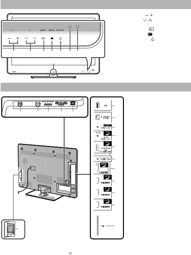
TV (front view)
|
|
|
1 |
VOL |
/ |
(Volume buttons) |
|
|
|
2 |
CH |
/ |
(Programme [channel] |
|
|
|
|
buttons) |
|
|
|
|
|
3 |
INPUT |
(Input source button) |
|
|
|
|
4 |
MENU |
(Menu button) |
|
|
|
|
5 |
POWER |
(Power button) |
|
|
|
|
6 |
OPC sensor |
||
|
|
|
7 |
Remote control sensor |
||
1 |
2 |
3 4 5 6 7 |
8 |
Illumination LED |
||
|
|
8 |
|
|
|
|
TV (rear view)
|
|
|
|
|
1 |
Antenna terminal |
|
|
|
|
|
6 |
2 |
Satellite antenna terminal |
|
|
|
|
|
3 |
EXT 1 (RGB) terminal |
||
|
|
|
|
|
|||
1 |
2 |
3 |
4 |
5 |
4 |
RS-232C terminal |
|
5 |
DIGITAL AUDIO OUTPUT |
||||||
|
|
|
|
7 |
|||
|
|
|
|
|
|
terminal |
|
|
|
|
|
8 |
6 |
USB terminal |
|
|
|
|
|
|
7 |
ETHERNET (10/100) terminal |
|
|
|
|
|
9 |
8 |
OUTPUT (Headphones/AUDIO |
|
|
|
|
|
|
|
(L/R)) terminal |
|
|
|
|
|
10 |
9 |
EXT 2 (AV IN/VIDEO/AUDIO (L/R)) |
|
|
|
|
|
|
terminal |
||
|
|
|
|
|
|
||
|
|
|
|
*1 |
10 |
EXT 3 (ANALOGUE RGB (PC/ |
|
|
|
|
|
11 |
|
COMPONENT)) terminal |
|
|
|
|
|
|
11 |
HDMI 2/EXT 3 AUDIO (L/R) jack |
|
|
|
|
|
12 |
12 |
HDMI 1 (HDMI/ARC) terminal |
|
|
|
|
|
|
13 |
HDMI 2 (HDMI) terminal |
|
|
|
|
|
13 |
14 |
HDMI 3 (HDMI) terminal |
|
|
|
|
|
15 |
HDMI 4 (HDMI) terminal |
||
|
|
|
|
|
|||
|
|
|
|
|
16 |
C.I. (COMMON INTERFACE) slot |
|
|
|
|
|
14 |
17 |
MAIN POWER switch |
|
|
|
|
|
|
WARNING |
||
|
|
|
|
15 |
• Excessive sound pressure from earphones |
||
|
|
|
|
|
and headphones can cause hearing loss. |
||
|
|
|
|
|
|
||
|
|
|
|
|
• Do not set the volume at a high level. |
||
|
|
|
|
|
|
Hearing experts advise against extended |
|
|
|
|
|
|
|
listening at high volume levels. |
|
*2 |
|
|
|
16 |
|
|
|
17 |
|
|
|
|
|
|
|
*1 The HDMI 2 and EXT 3 terminals can both use the same audio input terminal (HDMI 2/EXT 3 AUDIO (L/R)). However, the proper item must be selected in the “Audio select” menu.
*2 When the MAIN POWER switch is turned off ( ), the amount of electric power consumed will be reduced to 0.01 W or less. However, unlike when unplugging the AC cord, the power is not completely disconnected.
2 – 1
LC-40/46LE814/824E/RU (1st Edition)
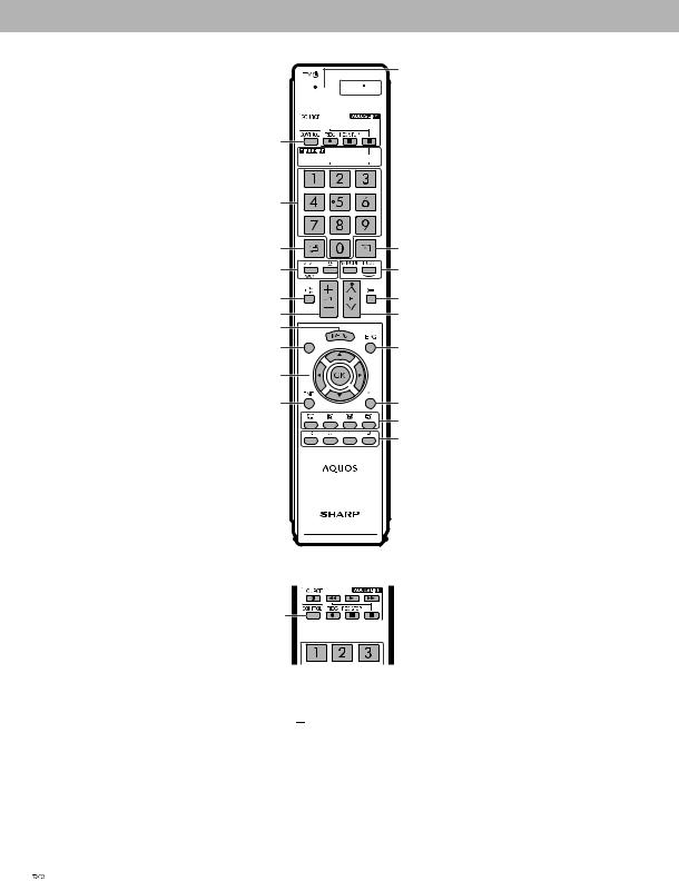
Remote control unit
1TV (Standby/On)
2ATV
Press to access conventional analogue TV mode.
DTV
Press to access digital TV mode.
SAT
Press to access satellite mode.
LE824E
15 1 


 16 2
16 2 


3 


4
5 


RADIO
DTV/SAT: Switch between radio and data mode.
•When only data broadcasting (no radio broadcasting) is transmitted by DVB, the radio broadcasting will be skipped.
3AQUOS LINK buttons
If external equipment such as a AQUOS BD player is connected via HDMI cables and is AQUOS LINK compatible, you can use these AQUOS LINK buttons.
•The four buttons ( ,
, ,
, ,
,
 ) function during time shift (for the 824 model series), Home Network and Net TV.
4CONTROL
Press to display the panel to operate some functions on the screen.
5TIME SHIFT (READY/ /
/  /
/ )
)
Press to temporarily record a programme you are watching if you want to interrupt a programme to answer a phone call, for example.
•This function is available only for the 824 model series.
6Numeric buttons 0_9
Set the channel.
Enter desired numbers.
Set the page in teletext mode.
•When the five Nordic countries (Sweden, Norway, Finland, Denmark or Iceland) are selected in the country setting from
“Auto installation”, DTV services are four digits. When another country is selected, DTV services are three digits.
7 (Flashback)
Press to return to the previously selected channel or external input.
8 (Sound mode)
Select a sound multiplex mode.
 (Wide mode)
Select a wide mode.
6 |
|
7 |
17 |
8 |
18 |
9 |
19 |
10 |
20 |
11 |
|
12 |
21 |
13 |
|
14 |
22 |
|
23 |
|
24 |
LE814E
3 

4
9 (Mute)
TV sound on/off.
10  / (Volume)
Increase/decrease TV volume.
11MENU
“Menu” screen on/off.
12None
This key does not work on this model.
13 /
/ /
/ /
/  (Cursor)
Select a desired item.
OK
Execute a command. ATV/DTV/SAT: Display “CH list” when no other “Menu” screen is running.
14END
ATV/DTV/SAT: Exit the “Menu” screen.
NET: Return to the start page.
15NET
Press to access Net TV.
16 (Display information)
Press to display the station information (channel number, signal, etc.) in the upper right corner of the screen.
P. INFO
Press to display programme information transmitted through digital video broadcasting (DTV/ SAT only).
17 (INPUT)
Select an input source.
18AV MODE
Select a video setting.
ECO (Standard/Advanced/Off)
Select “Energy save” setting.
19 (Teletext)
ATV: Display analogue teletext.
DTV/SAT: Select MHEG-5 or teletext for DTV/SAT.
20P /
/
ATV/DTV/SAT: Select the TV channel.
NET: Scrolls pages up/down.
21EPG
DTV/SAT: Display the EPG screen.
22 (Return)
ATV/DTV/SAT: Return to the previous “Menu” screen.
NET: Return to the previous page (This may not function for some services).
23Buttons for useful operations
 (Subtitle)
Switch subtitle languages on/off.
 (Reveal hidden teletext)
 (Subpage)
 (Freeze/Hold)
Press to freeze a moving image on the screen.
Teletext: Stop updating teletext pages automatically or release the hold mode.
24R/G/Y/B (Colour) buttons
The coloured buttons are correspondingly used to select the coloured items on the screen (e.g., EPG, MHEG-5, teletext).
2 – 2
LC-40/46LE814/824E/RU (1st Edition)
Attaching the stand unit
• Before performing work, spread cushioning over the surface on which you will be laying the TV. This will prevent it from being damaged.
CAUTION
•Attach the stand in the correct direction.
•Be sure to follow the instructions. Incorrect installation of the stand may result in the TV falling over.
1Confirm that there are nine screws (four long screws and five short screws) with the stand unit.
2Attach the supporting post for the stand unit onto the base using the four long screws with a screwdriver as shown.
Supporting
post
3Insert the stand into the openings on the bottom of the TV (hold the stand so it will not drop from the edge of the base area).
Soft cushion
4Insert and tighten four short screws into the four holes on the rear of the TV.
5Attaching the stand cover.
Slide the stand cover into the two catches on the stand base.
Insert and tighten a short screw into the hole on the centre of the stand cover.
NOTE
• To detach the stand unit, perform the steps in reverse order.
• A screwdriver is not supplied with this product.
• The stand base is made of glass. Therefore, be careful not to drop the stand base or apply pressure to it.
• Do not place heavy objects on the stand base.
CAUTION
The stand is made of tempered glass. Read the following precautionary instructions carefully and use it properly.
•Do not drop or place unnecessary stress on the stand when assembling and attaching or removing it.
•Be sure to not accidentally hit the glass part of the stand with a sharp or hard object, as it may cause the glass to break.
•Using tempered glass with scratches for extended periods may lead to damage occurring. If there are scratches on the tempered glass, do not attempt to use the stand.
2 – 3
LC-40/46LE814/824E/RU (1st Edition)
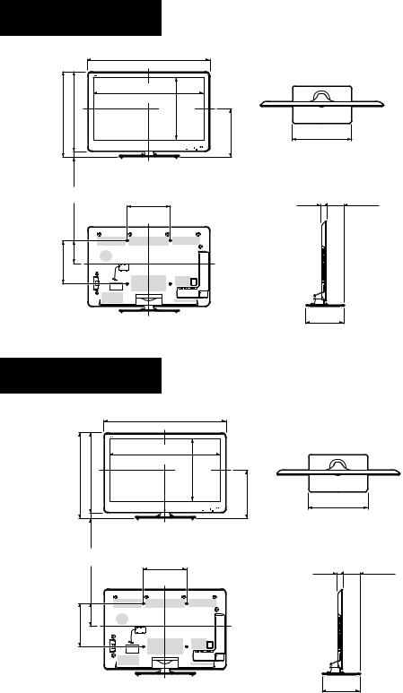
CHAPTER 3. DIMENSIONS
[1] DIMENSIONS
LC-46LE824E LC-46LE824RU
LC-40LE824E LC-40LE824RU
(1127.0 )/ [ 993.0 ]
(1127,0 )/ [ 993,0 ]
] ] |
] ] |
|
(1023.4)/ [ 890.6 ] |
|
|
|
|
|
|
|
||||
707.0 |
707,0 |
659.0 |
659,0 |
|
|
) |
) |
] |
] |
|
|
|
|
|
785.0 |
785,0 |
734.0 |
734,0 |
|
(1023,4)/ [ 890,6 |
] |
577,6 |
503.2 |
503,2 |
|
|
|
|
|
|
|
|
577.6 |
) |
) |
] |
] |
|||||||
[ |
[ |
[ |
[ |
|
|
|
|
|
|
|
|
|
|
|
/ / |
/ / |
|
|
|
|
|
|
|
|
|
|
|
||
) ) |
) ) |
|
|
|
|
|
|
|
|
|
|
|
||
( |
( |
( |
( |
|
|
( |
( |
[ |
[ |
444.0 |
444,0 |
404.0 |
404,0 |
|
|
|
|
|
|
|
|
|
|
|
|
( ( [ [ |
|||
|
) ) |
] ] |
|
|
|
|
|
|
|
|
|
|
||
|
51.0 |
51,0 |
48.0 |
48,0 |
|
|
|
|
|
|
|
|
|
|
|
( ( |
[ [ |
|
|
|
|
|
|
|
|
|
|
||
|
|
|
|
|
( 400.0 ) |
|
|
|
|
|
|
|
|
|
|
) ) |
] ] |
( 400,0 ) |
|
|
|
|
|
|
|
|
|||
|
211.0 |
211,0 |
132.0 |
132,0 |
[ 300,0 |
] |
|
|
|
|
|
|
|
|
|
|
|
|
|
[ 300.0 |
] |
|
|
|
|
|
|
|
|
|
( ( |
[ [ |
|
|
|
|
|
|
|
|
|
|
||
] ] |
|
|
|
|
|
|
|
|
|
|
|
|
|
|
300.0 |
300,0 |
|
|
|
|
|
|
|
|
|
|
|
|
|
[ [ |
|
|
|
|
|
|
|
|
|
|
|
|
|
|
/ / |
|
|
|
|
|
|
|
|
|
|
|
|
|
|
) ) |
|
|
|
|
|
|
|
|
|
|
|
|
|
|
400.0 |
400,0 |
|
|
|
|
|
|
|
|
|
|
|
|
|
( ( |
|
|
|
|
|
|
|
|
|
|
|
|
|
|
Unit: inch (mm)
( ) : LC-46LE824E LC-46LE824RU
[] : LC-40LE824E LC-40LE824RU
(540.0 ) (540,0 )
[ 450.0 ] [ 450,0 ]
( 157.7 )
39.0( 157,7 )
39,0 |
[ 124.6 ] |
|
[ 124,6 ] |
( 340.0 ) ( 340,0 )
[ 275.0 ] [ 275,0 ]
LC-46LE814E LC-46LE814RU
LC-40LE814E LC-40LE814RU
(1125.0 )/ [ 992.0 ]
(1125,0 )/ [ 992,0 ]
] ] |
] |
] |
(1020.8)/ [ 887.8 ] |
|
|
|
|
|
|
|
||||
706.0 |
706,0 |
658.0 |
658,0 |
|
|
) |
) |
] |
] |
|
|
|
|
|
784.0 |
784,0 |
733.0 |
733,0 |
(1020,8) |
/ [ 887,8 |
] |
575,4 |
500.4 |
500,4 |
|
|
|
|
|
|
|
|
575.4 |
) |
) |
] |
] |
|||||||
[ |
[ |
[ [ |
|
|
|
|
|
|
|
|
|
|
|
|
/ / |
/ / |
|
|
|
|
|
|
|
|
|
|
|
||
) ) |
) ) |
|
|
|
|
|
|
|
|
|
|
|
||
( |
( |
( |
( |
|
|
( |
( |
[ |
[ |
444.0 |
444,0 |
404.0 |
404,0 |
|
|
|
|
|
|
|
|
|
|
|
|
( ( [ [ |
|||
|
) ) |
] ] |
|
|
|
|
|
|
|
|
|
|
||
|
51.0 |
51,0 |
48.0 |
48,0 |
|
|
|
|
|
|
|
|
|
|
|
( ( |
[ [ |
|
|
|
|
|
|
|
|
|
|
||
|
|
|
|
|
( 400.0 ) |
|
|
|
|
|
|
|
|
|
|
) ) |
] ] |
( 400,0 ) |
|
|
|
|
|
|
|
|
|||
|
211.0 |
211,0 |
132.0 |
132,0 |
[ 300,0 |
] |
|
|
|
|
|
|
|
|
|
|
|
|
|
[ 300.0 |
] |
|
|
|
|
|
|
|
|
|
( ( |
[ [ |
|
|
|
|
|
|
|
|
|
|
||
] ] |
|
|
|
|
|
|
|
|
|
|
|
|
|
|
300.0 |
300,0 |
|
|
|
|
|
|
|
|
|
|
|
|
|
[ [ |
|
|
|
|
|
|
|
|
|
|
|
|
|
|
/ / |
|
|
|
|
|
|
|
|
|
|
|
|
|
|
) ) |
|
|
|
|
|
|
|
|
|
|
|
|
|
|
400.0 |
400,0 |
|
|
|
|
|
|
|
|
|
|
|
|
|
( ( |
|
|
|
|
|
|
|
|
|
|
|
|
|
|
NOTE
• Dimensions do not include protrusions such as screws and some parts.
( ) : LC-46LE814E LC-46LE814RU
[] : LC-40LE814E LC-40LE814RU
(540.0 ) (540,0 )
[ 450.0 ] [ 450,0 ]
( 157.1 )
39.5( 157,1 )
39,5 |
[ 124.0 ] |
|
[ 124,0 ] |
( 340.0 ) ( 340,0 )
[ 275.0 ] [ 275,0 ]
3 – 1
LC-40/46LE814/824E/RU (1st Edition)
CHAPTER 4. ADJUSTMENT
[1] ADJUSTMENT PROCEDURE
1. Adjustment method after PWB and/or IC replacement due to repair
The unit is set to the optimum at the time of shipment from the factory.
If any value should become improper or any adjustment is necessary due to the part replacement, make an adjustment according to the following procedure.
1.Procure the following units in order to replace the main unit
MAIN UNIT: DKEYDF455FM11 (LC-40LE814E/RU, LC-46LE814E/RU) DKEYDF455FM12 (LC-40LE824E/RU, LC-46LE824E/RU)
NOTE: [Caution when replacing ICs in the main unit (IC501, IC2002)]
The above ICs are EEPROMs storing the EDID data of PC, and Monitor microcomputer.
Before replacing the relevant part, procure the following parts in which the data have been rewritten.
IC501 |
RH-iXD108WJQZS |
PC EDID |
IC2002 |
RH-iXC786WJNJQ |
Monitor microcomputer |
NOTE: [Caution when replacing ICs in the main unit (IC8401, IC3302)]
When replacing either IC8401 or IC3302, exchange MAIN units for DKEYDF455FM11/12
Each part should not be individually exchanged.
IC8401 |
RH-iXD047WJQZQ |
Flash |
IC3302 |
RH-iXC951WJN1Q |
Main CPU |
NOTE: HDMI ROM Writing
After replacing IC1504, execute “HDMI EDID WRITE” on the page 5/21
Please execute it after checking MODEL NAME & INCH SIZE. are correct.
IF MODEL NAME & INCH SIZE. are not correct, set them previously. (Refer to 2)
The ROM data based on information of MODEL NAME & INCH SIZE
1)Enter the process adjustment mode in TV.
2)Use the cursor keys ( /
/ ) and CH keys (
 /
/ ) of R/C to select the item [HDMI EDID WRITE] on the page 5/21.
2.After replacing the LCD panel or LCD control/MAIN UNIT, check MODEL NAME in the following procedure.
1)Enter the process adjustment mode in TV.
2)Use the cursor keys ( /
/ ) and CH keys (
 /
/ ) of R/C to select the item [MODEL NAME] on the page 21/21.
3)Verify that the Model name is displayed.
4)If the Model name doesn't match, select the values of the Model name with the VOL keys (+/-).
5)After selection in Step 4), press the OK key, and it is completed with OK displayed.
6)Use the cursor keys ( /
/ ) and CH keys (
 /
/ ) of R/C to select the item [PANEL_SIZE] on the page 21/21.
7)Verify that the panel size is displayed.
8)If the size doesn't match, select the values of the panel size with the VOL keys (+/-).
9)After selection in Step 8), press the OK key, and it is completed with OK displayed.
3.After replacing the LCD panel or LCD control PWB, adjust the VCOM in the following procedure.
1)Enter the process adjustment mode.
2)Use the cursor keys ( /
/ ) and CH keys (
 /
/ ) of R/C to select the item [VCOM ADJ] on the page 10/21.
3)Press the OK key to verify that the adjustment pattern is displayed.
4)Use VOL keys (+/-) of R/C to adjust the flicker in the center of the screen to minimum.
5)When the optimal state is achieved in Step 4, press the OK key to turn the pattern to OFF.
4 – 1

LC-40/46LE814/824E/RU (1st Edition)
2. Notes of Touch sensor unit (LC-40LE824E/RU, LC-46LE824E/RU)
Touch sensor unit (RUNTKA761WJQZ) is fixed directly in the module glass. The unit cannot never be recycled when exfoliated from the module glass.
Therefore, please exchange the touch sensor units when the module glass is changed.
Please note the adhesion and mixing of dust for the module glass when the module glass and the touch sensor unit are exchanged.
Module glass for LE824
40inch: CPNLHA019WE14 46inch: CPNLHA020WJ12
3. Method of shuts down for Power supply
Please execute the following procedures to shut down Power supply from the state of normal operation.
1)Keep touching the power supply key on the set for 5 seconds from the state of watching.
*The screen disappears when power supply key is touched, but Keep pushing the power supply key.
2)A central icon lights between 500ms when the power supply shuts down.
Please separate the finger from the power supply key when lighting of a central icon is confirmed
4. Entering and exiting the adjustment process mode
Please execute the following procedures to enter the adjustment process mode when the power supply shuts down.
1)While holding down the “VOL (-)” and “INPUT” keys on the set at once, touch the power supply key on the set. Please separate the fingers from key on the set when boot-up is confirmed with lighting of a central icon etc. After a while, The letter “K” appears on the screen. This state is in Inspection mode.
2)Next, hold down the “VOL (-)” and “CH ( )” keys on the set at once.
Multiple lines of blue characters appearing on the screen indicate that the set is now in the adjustment Process mode. If you fail to enter the adjustment process mode (the display is the same as normal startup), retry the procedure.
3)To exit the adjustment process mode after the adjustment is done, unplug the AC power cord to force off the power.
(When the power is turned off with the remote controler, once unplug the AC power cord and plug it in again. In this case, wait for 10 seconds or so after unplugging.)
CAUTION: Use due care in handling the information described here lest the users should know how to enter the adjustment process mode. If the settings are tampered with in this mode, unrecoverable system damage may result.
5. Remote controler key operation and description of display in adjustment process mode.
1. Key operation
Remote controler key |
Main unit key |
Remote controler key Main unit key Function |
||
CH keys ( |
|
/ ) |
CH ( / ) |
Moving an item (line) by one (UP/DOWN) |
VOL keys (+/-) |
VOL (+/-) |
Changing a selected item setting (+1/-1) |
||
Cursor ( |
/ |
) |
— |
Turning a page (PREVIOUS/NEXT) |
Cursor ( |
/ |
) |
— |
Changing a selected line setting (+10/-10) |
INPUT |
|
|
INPUT |
Input source switching (toggle switching) (TV→DTV, Input1~7) |
OK |
|
|
— |
Executing a function |
RETURN |
|
|
— |
Returning to a present page |
Input mode is switched automatically when relevant adjustment is started so far as the necessary input signal is available.
4 – 2
|
LC-40/46LE814/824E/RU (1st Edition) |
6. Description of display |
|
(1) Present page / number of total pages |
(4) Inducing display |
(3) Present colour system |
|
(2) Input that has been selected now |
(5) Inch setting and Model name display |
1/21 INPUT1
MAIN Version
BOOT Version
Monitor Version
T-CON Version/LED CON Version
CPLD Version
CI+INFO/SECURE BOOT
FRC-N Auto Script Version
TCON Master/Slave Serial Version
TOUCH SENSOR UCON VERSION
LAMP ERROR
MONITOR ERR CAUSE
NORMAL STANDBY CAUSE ERROR STANDBY CAUSE
AUTO |
EURO |
xxxxx |
1.00 (E 2009/**/** ) xxxxxxx
xxxxxxx xxxxxxxx/xxxx xxxxxxx xxxxx/YES xxxxxxx xxxxxxx xxxxxxx
0
1)xxxxxx 2)xxxxxx 3)xxxxxx 4)xxxxxx 0 0 0 0 0
|
(6) Item name |
(7) Parameter |
|
|
|
|
|
|
No. |
Description |
Display specification |
(1) |
Present page/number of total pages |
2char/2char Decimal Number mark. |
(2) |
Input that has been selected now |
TUNER/DTV/INPUT1/INPUT2/INPUT3/INPUT5/INPUT6/INPUT7 |
(3) |
Present colour system |
AUTO/N358/N443/PAL/SECAM/480i/580i/1080i/50 etc. |
(4) |
Inducing display |
EUROPE/RUSSIA/SWEDEN |
(5) |
Inch setting and Model name display |
Inch setting and Model name display |
(6) |
Item name |
Max. 30 char |
(7) |
Parameter |
Max. 60 char |
4 – 3
LC-40/46LE814/824E/RU (1st Edition)
7. Adjustment process mode menu
The character string in brackets [ ] will appear as a page title in the adjustment process menu header.
Page |
Line |
Item |
Description |
Remarks (adjustment detail, etc.) |
|
1/21 |
|
|
|
|
|
|
|
1 |
MAIN Version |
1xxx (xxxxx) |
Main software version |
|
|
2 |
BOOT Version |
xxxxxxx |
BOOT Version. |
|
|
3 |
Monitor Version |
xxxxxxx |
Monitor software version |
|
|
4 |
T-CON Version/LED CON Version |
xxxxxxxx/xxxx |
T-CON/H.264 Version |
|
|
5 |
CPLD Version |
xxxxxxx |
CPLD Version. |
|
|
7 |
CI+INFO/SECURE BOOT |
xxxxx/YES |
CI+ Key Information/SECURE BOOT |
|
|
8 |
FRC-N Auto Script Version |
xxxxxxx |
|
|
|
9 |
TCON Master/Slave Serial Version |
xxxxxxx |
|
|
|
10 |
TOUCH SENSOR UCON VERSION |
xxxxxxx |
|
|
|
11 |
LAMP ERROR |
0 |
Number of termination due to lamp error. |
|
|
12 |
MONITOR ERR CAUSE |
1) xxxxxx 2) xxxxxx |
Last error standby cause. |
|
|
|
|
3) xxxxxx 4) xxxxxx |
|
|
|
13 |
NORMAL STANDBY CAUSE |
0 |
Situation that became standby at the end. |
|
|
|
|
|
(Excluding the error) |
|
|
14 |
ERROR STANDBY CAUSE |
0 0 0 0 |
Error standby cause |
2/21 |
|
|
|
|
|
|
|
1 |
INDUSTRY INIT |
Enter |
Initialization to factory settings execution. |
|
|
2 |
INDUSTRY INIT (-Public) |
OFF |
Initialization to factory settings execution. |
|
|
|
|
|
(Public mode is excluded) |
|
|
3 |
PUBLIC MODE |
OFF |
Public mode ON/OFF setting |
|
|
4 |
Center Acutime |
— |
Main operating hours. |
|
|
5 |
RESET |
OFF |
Main operating hours reset. |
|
|
6 |
Backlight Acutime |
— |
Backlight operating hours. |
|
|
7 |
RESET |
OFF |
Backlight operating hours reset. |
|
|
8 |
LAMP ERROR RESET |
OFF |
Lamp error reset. |
|
|
9 |
ADJ PARAM SET |
Enter |
ADJ PARAM SET |
|
|
10 |
VIC XPOS |
0 |
X-coordinate setting for VIC READ |
|
|
11 |
VIC YPOS |
0 |
Y-coordinate setting for VIC READ |
|
|
12 |
VIC SIGNAL TYPE |
MAIN |
Signal type setting for VIC READ |
|
|
13 |
VIC READ |
OFF |
Picture level acquisition function |
|
|
|
|
|
(Level appears in green on the upper right) |
3/21 |
|
|
|
|
|
|
|
1 |
TUNER ADJ |
Enter |
TUNER auto adjustment execution |
|
|
2 |
PAL+TUNER ADJ |
Enter |
PAL TUNER auto adjustment execution |
|
|
3 |
TUNER ADJ (SMPTE) |
Enter |
TUNER auto adjustment execution (SMPTE) |
|
|
4 |
PAL+TUNER ADJ (SMPTE) |
Enter |
PAL TUNER auto adjustment execution (SMPTE) |
|
|
5 |
TUNER ADJ (SMPTE CH57) |
Enter |
TUNER auto adjustment execution (SMPTE CH57) |
|
|
6 |
PAL+TUNER ADJ (SMPTE CH57) |
Enter |
PAL TUNER auto adjustment execution (SMPTE CH57) |
|
|
7 |
TUNER CONTRAST A_GAIN |
16 |
TUNER signal level adjustment |
|
|
8 |
TUNER CONTRAST D_GAIN |
2073 |
TUNER signal level adjustment |
|
|
9 |
TUNER CONTRAST OFFSET |
256 |
TUNER signal level adjustment |
4/21 |
|
|
|
|
|
|
|
1 |
PAL ADJ |
Enter |
PAL adjustment |
|
|
2 |
SECAM ADJ |
Enter |
SECAM adjustment |
|
|
3 |
N358 ADJ |
Enter |
N358 adjustment |
|
|
4 |
PAL CONTRAST A_GAIN |
14 |
PAL contrast adjustment |
|
|
5 |
PAL CONTRAST D_GAIN |
2149 |
PAL contrast adjustment |
|
|
6 |
PAL CONTRAST OFFSET |
255 |
PAL contrast adjustment |
|
|
7 |
SECAM CONTRAST A_GAIN |
14 |
SECAM contrast adjustment |
|
|
8 |
SECAM CONTRAST D_GAIN |
2123 |
SECAM contrast adjustment |
|
|
9 |
SECAM CONTRAST OFFSET |
256 |
SECAM contrast adjustment |
|
|
10 |
N358 CONTRAST A_GAIN |
14 |
N358 contrast adjustment |
|
|
11 |
N358 CONTRAST D_GAIN |
2192 |
N358 contrast adjustment |
|
|
12 |
N358 CONTRAST OFFSET |
255 |
N358 contrast adjustment |
4 – 4
|
|
|
|
|
LC-40/46LE814/824E/RU (1st Edition) |
|
|
|
|
|
|
Page |
Line |
Item |
Description |
Remarks (adjustment detail, etc.) |
|
5/21 |
|
|
|
|
|
|
|
1 |
HDMI CEC TEST |
Enter |
HDMI CEC test |
|
|
2 |
INSPECT USB TERM |
Enter |
Reading inspection of USB memory terminal |
|
|
3 |
HDMI EDID WRITE |
Enter |
HDMI EDID WRITING |
|
|
4 |
MONIDATA READ [TEMP/OPC] |
OFF |
MONITOR Temperature/OPC Acquisition tool. |
|
|
5 |
CAUSE RESET |
Enter |
Reset of standby cause |
|
|
6 |
SD CARD TEST |
Size 1 |
SD CARD TEST |
|
|
|
|
|
(*This item is LC-40/46LE824E/RU only) |
|
|
7 |
SD CARD REC SIZE |
xx |
SD CARD REC SIZE |
|
|
|
|
|
(*This item is LC-40/46LE824E/RU only) |
|
|
8 |
RESET |
OFF |
SD CARD RESET |
|
|
|
|
|
(*This item is LC-40/46LE824E/RU only) |
6/21 |
|
|
|
|
|
|
|
1 |
COMP15K ALL ADJ |
Enter |
Component 15K picture level adjustment |
|
|
2 |
COMP15K MAIN Y GAIN |
141 |
Y GAIN adjustment value |
|
|
3 |
COMP15K MAIN CB GAIN |
150 |
Cb GAIN adjustment value |
|
|
4 |
COMP15K MAIN CR GAIN |
150 |
Cr GAIN adjustment value |
|
|
5 |
COMP15K Y OFFSET |
64 |
Y OFFSET adjustment value |
|
|
6 |
COMP15K CB OFFSET |
128 |
Cb OFFSET adjustment value |
|
|
7 |
COMP15K CR OFFSET |
128 |
Cr OFFSET adjustment value |
7/21 |
|
|
|
|
|
|
|
1 |
HDTV ADJ |
Enter |
HDTV video level adjustment |
|
|
2 |
HDTV Y GAIN |
141 |
HDTV Y GAIN adjustment value |
|
|
3 |
HDTV CB GAIN |
150 |
HDTV Cb adjustment value |
|
|
4 |
HDTV CR GAIN |
150 |
HDTV Cr adjustment value |
|
|
5 |
HDTV Y OFFSET |
64 |
HDTV Y OFFSET adjustment value |
|
|
6 |
HDTV CB OFFSET |
128 |
HDTV Cb OFFSET adjustment value |
|
|
7 |
HDTV CR OFFSET |
128 |
HDTV Cr OFFSET adjustment value |
8/21 |
|
|
|
|
|
|
|
1 |
ANALOG PC ADJ |
Enter |
DVI ANALOG video level adjustment |
|
|
2 |
R OFFSET |
64 |
R CUTOFF adjustment value |
|
|
3 |
G OFFSET |
64 |
G CUTOFF adjustment value |
|
|
4 |
B OFFSET |
64 |
B CUTOFF adjustment value |
|
|
5 |
R GAIN |
44 |
R DRIVE adjustment value |
|
|
6 |
G GAIN |
44 |
G DRIVE adjustment value |
|
|
7 |
B GAIN |
44 |
B DRIVE adjustment value |
9/21 |
|
|
|
|
|
|
|
1 |
SCART RGB ADJ |
Enter |
SCART RGB level adjustment |
|
|
2 |
SCART R CUTOFF |
64 |
SCART R CUTOFF adjustment value |
|
|
3 |
SCART G CUTOFF |
64 |
SCART G CUTOFF adjustment value |
|
|
4 |
SCART B CUTOFF |
64 |
SCART B CUTOFF adjustment value |
|
|
5 |
SCART R GAIN |
44 |
SCART R GAIN adjustment value |
|
|
6 |
SCART G GAIN |
44 |
SCART G GAIN adjustment value |
|
|
7 |
SCART B GAIN |
44 |
SCART B GAIN adjustment value |
10/21 |
|
|
|
|
|
|
|
1 |
VCOM ADJ |
0 |
Common bias adjustment |
11/21 |
|
|
|
|
|
|
|
1 |
R GAIN (LO) |
0 |
R DRIVE adjustment value |
|
|
2 |
G GAIN (LO) |
0 |
G DRIVE adjustment value |
|
|
3 |
B GAIN (LO) |
0 |
B DRIVE adjustment value |
|
|
4 |
R GAIN (HI) |
0 |
R DRIVE adjustment value |
|
|
5 |
G GAIN (HI) |
0 |
G DRIVE adjustment value |
|
|
6 |
B GAIN (HI) |
0 |
B DRIVE adjustment value |
12/21 |
|
|
|
|
|
|
|
1 |
MONITOR TIME OUT |
ON |
Monitor and the main communication time-out setting |
|
|
2 |
MONITOR MAX TEMP |
45 |
MONITOR MAX temperature setting |
|
|
3 |
MONITOR EEP READ/WRITE |
WRITE |
MONITOR EEPROM READ/WRITE Setting/execution |
|
|
4 |
MONITOR EEP ADR |
0x 0 |
MONITOR EEPROM arbitrary addressing |
|
|
5 |
MONITOR EEP DATA |
0x 0 |
MONITOR EEPROM arbitrary data specification |
13/21 |
|
|
|
|
|
|
|
1 |
LCD TEST PATTERN |
OFF |
Pattern with built-in LCD controler display |
|
|
2 |
LCD TEST PATTERN 1 |
OFF |
|
|
|
3 |
LCD TEST PATTERN 2 |
OFF |
|
|
|
4 |
LCD TEST PATTERN 3 |
OFF |
|
|
|
5 |
LCD TEST PATTERN 4 |
OFF |
|
4 – 5
LC-40/46LE814/824E/RU (1st Edition)
Page |
Line |
Item |
Description |
Remarks (adjustment detail, etc.) |
|
14/21 |
|
|
|
|
|
|
|
1 |
FRV-N Firmware Version |
xxxxx |
|
|
|
2 |
FRC-N Boot Script Version |
xxxxx |
|
|
|
3 |
FRC-N Device Version |
xxxxx |
|
|
|
4 |
TCON FPGA1 Serial Flash Version |
xxxxx |
|
|
|
5 |
TCON FPGA2 Serial Flash Version |
xxxxx |
|
|
|
6 |
TCON FPGA1 Config Rom Version |
xxxxx |
|
|
|
7 |
TCON FPGA2 Config Rom Version |
xxxxx |
|
15/21 |
|
|
|
|
|
|
|
1 |
POWER LED BRIGHTNESS |
0 |
|
|
|
2 |
MENU LED BRIGHTNESS |
0 |
|
|
|
3 |
INPUT LED BRIGHTNESS |
0 |
|
|
|
4 |
CH UP LED BRIGHTNESS |
0 |
|
|
|
5 |
CH DOWN LED BRIGHTNESS |
0 |
|
|
|
6 |
VOL UP LED BRIGHTNESS |
0 |
|
|
|
7 |
VOL DOWN LED BRIGHTNESS |
0 |
|
|
|
8 |
LOGO LED BRIGHTNESS |
99 |
|
|
|
9 |
ICON LED BRIGHTNESS |
99 |
|
|
|
10 |
ICON LED BRIGHTNESS (STANDBY) |
30 |
|
16/21 |
|
|
|
|
|
|
|
1 |
POWER KEY SENSITIVITY |
0 |
|
|
|
2 |
MENU KEY SENSITIVITY |
0 |
|
|
|
3 |
INPUT KEY SENSITIVITY |
0 |
|
|
|
4 |
CH UP KEY SENSITIVITY |
0 |
|
|
|
5 |
CH DOWN KEY SENSITIVITY |
0 |
|
|
|
6 |
VOL UP KEY SENSITIVITY |
0 |
|
|
|
7 |
VOL DOWN KEY SENSITIVITY |
0 |
|
17/21 |
|
|
|
|
|
|
|
1 |
KEY STRENGTH GET MODE |
Enter |
|
|
|
2 |
POWER KEY STRENGTH |
|
|
|
|
3 |
MENU KEY STRENGTH |
|
|
|
|
4 |
INPUT KEY STRENGTH |
|
|
|
|
5 |
CH UP KEY STRENGTH |
|
|
|
|
6 |
CH DOWN KEY STRENGTH |
|
|
|
|
7 |
VOL UP KEY STRENGTH |
|
|
|
|
8 |
VOL DOWN KEY STRENGTH |
|
|
18/21 |
|
|
|
|
|
|
|
1 |
READ/WRITE |
READ |
Read/Write |
|
|
2 |
SLAVE/ADDRESS |
SLAVE0 |
Slave address |
|
|
3 |
REGISTER ADDRESS |
0x 0 |
Register address |
|
|
|
|
0x 0 |
|
|
|
4 |
WRITE DATA |
0x 0 |
Writing data |
|
|
|
|
0x 0 |
|
|
|
5 |
READ DATA |
0x 0 |
Reading data |
|
|
|
|
0x 0 |
|
19/21 |
|
|
|
|
|
|
|
1 |
RF AGC BG |
6 |
RF-AGC BG adjustment execution |
|
|
2 |
RF AGC DK |
5 |
RF-AGC DKG adjustment execution |
|
|
3 |
RF AGC I |
6 |
RF-AGC I adjustment execution |
|
|
4 |
RF AGC L/L' |
4 |
RF-AGC L/L' adjustment execution |
20/21 |
|
|
|
|
|
|
|
1 |
ERROR STANDBY CAUSE 1 |
NO RECORD |
ERROR STANDBY CAUSE |
|
|
2 |
ERROR STANDBY CAUSE 2 |
NO RECORD |
|
|
|
3 |
ERROR STANDBY CAUSE 3 |
NO RECORD |
|
|
|
4 |
ERROR STANDBY CAUSE 4 |
NO RECORD |
|
|
|
5 |
ERROR STANDBY CAUSE 5 |
NO RECORD |
|
|
|
6 |
STANDBY CAUSE RESET |
OFF |
Reset stand by cause. |
4 – 6
|
|
|
|
LC-40/46LE814/824E/RU (1st Edition) |
|
|
|
|
|
Page |
Line |
Item |
Description |
Remarks (adjustment detail, etc.) |
21/21 |
|
|
|
|
|
1 |
EEP SAVE |
OFF |
Writing setting values to EEPROM. |
|
2 |
EEP RECOVER |
OFF |
Reading setting values from EEPROM. |
|
3 |
MONITOR ERROR CAUSE RESET |
OFF |
Reset of monitor error cause |
|
4 |
MODEL NAME |
LE824 |
MODEL NAME |
|
5 |
PANEL SIZE |
40 |
Panel size setting. |
|
6 |
SHORT CHECK MODE |
Enter |
Check LED Back light |
|
7 |
SHORT CHECK CURRENT |
60 |
|
|
8 |
CURRENT SW |
LOW |
|
|
9 |
PRODUCT EEP ADR |
0x 0 |
Don't touch when serving (for producer of factory) |
|
10 |
PRODUCT EEP DATA |
0x 0 |
Don't touch when serving (for producer of factory) |
|
11 |
PRODUCT FACTORY |
1 |
Don't touch when serving (for producer of factory) |
8. Special features
1.NORMAL STANDBY CAUSE (Page 1/21) Display of a cause (code) of the last standby.
The cause of the last standby is recorded in EEPROM whenever it is possible. Checking this code will be useful in finding a problem when you repair the troubled set.
2.EEP SAVE (Page 21/21) Storage of EEP adjustment value
3.EEP RECOVER (Page 21/21)
Retrieval of EEP adjustment value from storage area.
4.MONITOR ERR CAUSE (Page 1/21)
Display of a cause (code) of Error from sub-Microcomputer.
The cause of Error is recorded in EEPROM whenever it is possible.
Checking this code will be useful in finding a problem when you repair the troubled set.
1)This displays Error code and time when the error occurred. The latest error is displayed on “1)”
The error that happens ahead of “1)” is displayed on “2)”.
2)The character depends on the way how to acquire Time Information
T:Time is acquired from digital broadcasting
This doesn't contain “Time offset” which is considered a time difference and Daylight-Saving Time, etc. ...
U:Time is acquired from analog broadcasting (teletext)
B:Accumulation time of Backlight
In the case that Time information cannot be acquired, “B” is displayed.
Example) In this example, it is shown that the error occurred 3 times.
1) |
16 |
T07/01/01 12:03 |
Error code: 16 (lamp error) |
Time: 07/01/01 12:03 |
|
|
|
* It is latest Error. |
|
|
|
|
* Time is acquired from digital broadcasting. |
|
|
|
|
* Time is UTC which doesn't have Time offset. |
|
2) |
16 |
U01/01/01 04:07 |
Error code: 16 (lamp error) |
Time: 07/01/01 04:07 |
|
|
|
* It is Error that happens ahead of “1)”. |
|
|
|
|
* Time is acquired from analogue broadcasting. |
|
3) |
16 |
B00000004:11 |
Error code: 16 (lamp error) |
Accumulation time: It is displayed that 4:11 have passed after Backlight driving. |
*It is Error that happens ahead of “2)”.
4)00 0000000000000 No error (“00” shows that the error is not occurred.)
4 – 7

LC-40/46LE814/824E/RU (1st Edition)
9. Lamp Error detection
1.Function
This LCD colour TV set incorporates a Lamp error detection feature that automatically turns off the power for safety under abnormal lamp or lamp circuit conditions. If by any chance anything is wrong with the lamp or lamp circuit or if the lamp error detection feature is activated for some reason, the following will result.
1)The power is interrupted in about 500ms after it is turned on.
(A central icon on the front of the TV flash on and off.: ON for 400ms and OFF for 1600ms.).
2)If the above phenomenon 1) occurs 5 times, it becomes impossible to turn on the power. (A central icon keep flashing on/off.)
2.Measures
1)Set the lamp error detection to OFF
Enter the adjustment process mode, referring to “4. Entering and exiting the adjustment process mode.”
The adjustment process mode can ignore “5 times count”, so If the above phenomenon 1) occurs 1~4 times, the lamp will go out.
If Lamp Error detection pin (6pin of LB: P9602) is “High” by a trouble with the lamp and lamp circuit, it can boot-up by the adjustment process mode.
Please execute “Lamp Error detection off-mode”.
While holding down the “VOL (-)” and “CH ( )” keys on the set at once, touch the power supply key on the set. After a central icon flash off, separate the fingers from key on the set.
Touch the power supply key on the set again, so the power will boot-up.
Then, you can check the operation to see if the lamp and lamp circuit are in trouble. If you fail boot-up, retry the procedure.
2)Resetting the lamp error count
After the lamp and lamp circuit are improved from a trouble, reset the lamp error count. (Because the power cannot be turned on, if a lamp error is detected 5 consecutive times)
a)Enter the adjustment process mode, referring to “4. Entering and exiting the adjustment process mode.”
b)Using the cursor ( /
/ ) key, move to the cursor to [LAMP ERROR RESET], Line 8 on adjustment process mode service page 2/21.
c)With the cursor ( /
/ ) keys, select the [LAMP ERROR RESET] value. Finally press the cursor (OK)., the count is reset.
Check LAMP ERROR Count on adjustment process mode Page 2/21.
Table of contents of adjustment process mode Page 2/21
INDUSTRY INIT |
Enter |
|
INDUSTRY INIT (-Public) |
OFF |
|
PUBLIC MODE |
OFF |
|
Center Acutime |
|
|
RESET |
OFF |
|
Backlight Acutime |
|
|
RESET |
OFF |
|
LAMP ERROR RESET |
OFF |
Resetting to "0" |
ADJ PARAM SET |
Enter |
|
VIC XPOS |
0 |
|
VIC YPOS |
0 |
|
VIC SIGNAL TYPE |
MAIN |
|
VIC READ |
OFF |
|
|
|
|
4 – 8
LC-40/46LE814/824E/RU (1st Edition)
10. Public Mode
1.Starting the Public Mode
• There are two following ways to display the PUBLIC Mode setting screen.
1)Method of needing password
a)Turn off the power, refer to “3. Method of shuts down for Power supply”
b)While holding down the “INPUT” and “Volume (+)” keys on the set at once, touch the power supply key on the set. Please separate the finger from the power supply key when boot-up is confirmed with lighting of a central icon etc. After a while, value of Public Mode appears on the screen.
c)Display the Pass Word input screen.
Public Mode |
Public Mode |
Public Mode |
Operation procedure
•The initial input position is the digit at the left end.
•For the numeric keys “0” to “9” of R/C, key input is accepted. Input of the other keys is prohibited.
•Change “—” to “ * ” by inputting the numeric key at the input position, and shift the input position rightward one digit.
•When three digits are completely input, the Pass Word is judged.
d)Check the Pass Word by inputting three digits.
If the Pass Word “0” “2” “7”, it shifts to the PUBLIC Mode setting screen.
In another case, the screen is erased, and it operates in the ordinary mode.
2.Exiting the Public Mode Setting screen
•There are two following ways to exit the Public Mode setting screen.
1)Turn off the power.
2)Select “Execution” in the PUBLIC_Mode to execute it. Activate the restart under the set content.
Here, the START input SOURCE setting is excluded since this item is referred to only when the power is turned on.
3.Set value of the Public Mode
• When the shipment setting is done, a set each value in Public Mode is initialized. (PUBLIC MODE in the process mode Setting of a flag is also initialized)
• Separately, the shipment beginnings when all except for each set value in Public Mode is initialized are provided for a process mode. (INDUSTRY INIT (-Public))
• Only when turning on the PUBLIC MODE item, each setting is effective.
• After it decides it with EXECUTE, it AC OFF/ON it to reflect a set value.
4 – 9

LC-40/46LE814/824E/RU (1st Edition)
4. Basic operation in the Public Mode
Vol (+/-) or Cursor ( / ) |
|
Change or execution of the set value. |
|
CH ( / ) or Cursor ( |
/ ) |
Movement to the selected item. |
|
Decision (ok) |
|
Execution (Used by the items “Execution” and “RESET”.) |
|
Public Mode setting screen. |
|||
|
|
|
|
Public Mode |
|
|
|
POWER ON FIXED |
[VARIABLE] |
|
|
SHUT DOWN MODE |
[NORMAL] |
|
|
MAXIMUM VOLUME |
[60] |
|
|
VOLUME FIXED |
[VARIABLE] |
|
|
VOLUME FIXED LEVEL |
[20] |
|
|
RC BUTTON |
[RESPOND] |
|
|
PANEL BUTTON |
[RESPOND] |
|
|
MENU BUTTON |
[RESPOND] |
|
|
AV POSITION FIXED |
[VARIABLE] |
|
|
ON SCREEN DISPLAY |
|
[YES] |
|
INPUT MODE START |
[NORMAL] |
|
|
INPUT MODE FIXED |
[VARIABLE] |
|
|
LOUD SPEAKER |
|
[ON] |
|
RC PATH THROUGH |
|
[OFF] |
|
232C POWON |
[DISABLE] |
|
|
PUBLIC MODE |
|
[ON] |
|
RESET |
|
|
|
EXECUTE |
|
|
|
|
|
|
|
5.Operation after “RESET”
Select “RESET” in the PUBLIC Mode, and it operates as follows when it is executed (refer to the basic operation).
•The set contents in the PUBLIC mode are initialized.
•It does not exit the PUBLIC mode.
•If “EXCUTE” is not executed, the content that does RESET is not reflected.
6.Setting items (* Item names and selective items are expressed in English.) 1) Power ON fixed [POWER ON FIXED]
Option |
“VARIABLE”, “FIXED_ALL”, “FIXED_BODYKEY” or “RCRESPOND” (loop enabled) |
|||
Default |
“VARIABLE” |
|
|
|
Function |
• |
VARIABLE |
: |
“POWER/RECEPTION” key on TV unit or remote control is enabled. |
|
• |
FIXED_ALL“ |
: |
“POWER/RECEPTION” key on TV unit or remote control is disabled. |
|
• |
FIXED_BODYKEY |
: |
only the “MAIN POWER” key on TV unit is disabled (the remote control is enabled). |
|
• |
RC RESPOND |
: |
the main unit’s POWER switch toggles between ON and Standby (the same operation by |
|
|
|
|
the remote control). |
Key disabled when set |
• |
OFF TIMER (SLEEP) (* Only when setting to FIXED_ALL) |
||
other than default |
|
|
|
|
Remarks |
• |
When selecting to “FIXED_ALL”, function related standby factors (see below) doesn't work. and not selecting |
||
|
|
OFF TIMER (Sleep) |
|
|
|
|
No operation OFF |
|
|
|
|
No signal OFF (including the power management) |
||
|
|
* These items does not exist according to the model. |
||
If the power button is pressed in the ordinary mode in setting to “FIXED_ALL” and “FIXED_BODYKEY”, the caution is displayed for 5 seconds.
When power button on the main unit is pressed When power button on R/C is pressed
No Power off by power button. |
|
No Power off by remote control. |
|
|
|
*The OSD display is an example.
If another ODS is previously displayed, the status is reset (MENU or similar).
4 – 10
 Loading...