


 Loading...
LC-46HD1E
LC-52HD1E
LCD COLOUR TELEVISION LCD-FARBFERNSEHGERÄT TÉLÉVISION COULEUR À ÉCRAN
À CRISTAUX LIQUIDES (LCD) TELEVISORE A COLORI LCD
OPERATION MANUAL
BEDIENUNGSANLEITUNG
MODE D’EMPLOI
MANUALE DI ISTRUZIONI
ENGLISH
DEUTSCH
FRANÇAIS
ITALIANO

SPECIAL NOTE FOR USERS IN THE U.K.
The mains lead of this product is fi tted with a non-rewireable (moulded) plug incorporating a 13A fuse. Should the fuse need to be replaced, a BSI or ASTA approved BS 1362 fuse marked  or ASA and of the same rating as above, which is also indicated on the pin face of the plug, must be used.
Always refi t the fuse cover after replacing the fuse. Never use the plug without the fuse cover fi tted.
In the unlikely event of the socket outlet in your home not being compatible with the plug supplied, cut off the mains plug and fi t an appropriate type.
DANGER:
The fuse from the cut-off plug should be removed and the cut-off plug destroyed immediately and disposed of in a safe manner.
Under no circumstances should the cut-off plug be inserted elsewhere into a 13A socket outlet, as a serious electric shock may occur.
To fi t an appropriate plug to the mains lead, follow the instructions below:
IMPORTANT:
The wires in the mains lead are coloured in accordance with the following code:
Blue: Neutral
Brown: Live
As the colours of the wires in the mains lead of this product may not correspond with the coloured markings identifying the terminals in your plug, proceed as follows:
•The wire which is coloured blue must be connected to the plug terminal which is marked N or coloured black.
•The wire which is coloured brown must be connected to the plug terminal which is marked L or coloured red. Ensure that neither the brown nor the blue wire is connected to the earth terminal in your three-pin plug. Before replacing the plug cover make sure that:
•If the new fi tted plug contains a fuse, its value is the same as that removed from the cut-off plug.
•The cord grip is clamped over the sheath of the mains lead, and not simply over the lead wires.
IF YOU HAVE ANY DOUBT, CONSULT A QUALIFIED ELECTRICIAN.

OPERATION MANUAL
ENGLISH
• The illustrations and on-screen displays in this operation manual are for explanation purposes and may vary slightly from the |
ENGLISH |
actual operations. |
|
• The examples used throughout this manual are based on the LC-52HD1E model. |
|
Contents
Contents ......................................................................................... |
1 |
Dear SHARP customer.................................................................. |
2 |
Important Safety Precautions ...................................................... |
2 |
Trademarks .................................................................................... |
2 |
Supplied accessories .................................................................... |
3 |
Preparation .................................................................................... |
3 |
Attaching the speaker unit ........................................................ |
3 |
Attaching the stand unit ............................................................ |
4 |
Detaching the stand unit ........................................................... |
4 |
Removing the terminal cover..................................................... |
4 |
Setting the TV ........................................................................... |
5 |
TV (Front view) .......................................................................... |
6 |
TV (Rear view)........................................................................... |
6 |
Inserting the batteries................................................................ |
7 |
Using the remote control unit .................................................... |
7 |
Cautions regarding the remote control unit........................... |
7 |
Remote control unit................................................................... |
8 |
Initial installation ........................................................................... |
9 |
Initial installation overview.......................................................... |
9 |
Initial installation wizard ........................................................... |
10 |
Positioning/aligning DVB-T antenna ................................... |
11 |
Daily operation............................................................................. |
12 |
Switching on/off...................................................................... |
12 |
TV indicator status ............................................................. |
12 |
Changing channels ................................................................. |
12 |
Selecting external video source............................................... |
13 |
Operation without remote control............................................ |
13 |
Status display ......................................................................... |
13 |
Additional DVB options ...................................................... |
13 |
Connecting external devices...................................................... |
14 |
Note on higher picture and sound quality ................................ |
14 |
Connection wizard .................................................................. |
15 |
HDMI connection............................................................... |
16 |
VGA/XGA connection (PC/SetTopBox)............................... |
16 |
Component connection (EXT3) .......................................... |
17 |
PC compatibility chart........................................................ |
18 |
Controlling HDMI devices using AQUOS LINK......................... |
19 |
Connecting HDMI device to TV ............................................... |
19 |
AQUOS LINK setup ........................................................... |
20 |
AQUOS LINK One Touch Recording .................................. |
20 |
Operating an AQUOS LINK device..................................... |
21 |
Listening with the AQUOS Audio speaker system ......... |
21 |
Manually changing AQUOS Audio speaker system’s |
|
sound mode............................................................... |
21 |
Playback of titles using AQUOS LINK ........................... |
21 |
Selecting media type for CEC-compatible recorder....... |
21 |
HDMI device selection .................................................. |
21 |
Recording via the AQUOS Recorder EPG (only for |
|
recorder) .................................................................... |
22 |
Using AV Link function ............................................................ |
22 |
Speaker/amplifier connection.................................................. |
22 |
Other features.............................................................................. |
23 |
Picture in Picture (PIP)............................................................. |
23 |
Using the PIP menu ........................................................... |
23 |
Using PhotoViewer ................................................................. |
24 |
Watching photos................................................................ |
24 |
Watching Slide show ......................................................... |
25 |
Using PhotoViewer menu................................................... |
25 |
EPG (Electronic Programme Guide)......................................... |
26 |
Using EPG menu ............................................................... |
27 |
Watching DVB broadcasts.......................................................... |
28 |
Conditional Access Module (CI Module) .................................. |
28 |
Software update ..................................................................... |
29 |
Radio mode ............................................................................ |
30 |
Menu operation............................................................................ |
31 |
Info display and index feature.................................................. |
31 |
Using info text.................................................................... |
31 |
Using Index........................................................................ |
31 |
Picture menu .......................................................................... |
32 |
AV mode............................................................................ |
32 |
Sound menu ........................................................................... |
32 |
Dolby Virtual Speaker ................................................... |
33 |
Recording menu ..................................................................... |
33 |
Recording wizard.......................................................... |
33 |
Timer list....................................................................... |
34 |
Preand post record time............................................. |
34 |
Timer recording with external devices ................................ |
34 |
Connections menu.................................................................. |
35 |
AV setup....................................................................... |
35 |
Antenna DVB................................................................ |
35 |
AV Link ......................................................................... |
35 |
Miscellaneous............................................................... |
35 |
Setup menu ............................................................................ |
36 |
Stations ........................................................................ |
36 |
Child lock...................................................................... |
37 |
Timer functions............................................................. |
38 |
PIP ............................................................................... |
38 |
Language ..................................................................... |
38 |
Miscellaneous............................................................... |
38 |
Extended functions menu ....................................................... |
38 |
Geometry menu...................................................................... |
38 |
Other menu items ................................................................... |
38 |
External Sources................................................................ |
38 |
Still image .......................................................................... |
38 |
Wide modes ...................................................................... |
39 |
Teletext ................................................................................... |
39 |
Using teletext menu ........................................................... |
40 |
HDD Digital Recorder operation ................................................ |
41 |
Important information.............................................................. |
41 |
Features.................................................................................. |
42 |
About time shift viewing and archive recording/playback......... |
43 |
Navigating the Digital Recorder menu ..................................... |
44 |
Setting pre-record time and post record time................ |
44 |
Recording with the HDD ......................................................... |
45 |
Buttons for HDD operation...................................................... |
45 |
Recording ............................................................................... |
46 |
Timer recording.................................................................. |
47 |
Playback................................................................................. |
48 |
Editing .................................................................................... |
49 |
Bookmark............................................................................... |
51 |
Appendix ...................................................................................... |
52 |
Troubleshooting ...................................................................... |
52 |
RS-232C port specifications ................................................... |
53 |
Using the universal remote control .......................................... |
55 |
Specifications ......................................................................... |
59 |
Optional accessories............................................................... |
59 |
End of life disposal.................................................................. |
60 |
WARNING:
This is a Class A product. In a domestic environment this product may cause radio interference in which case the user may be required to take adequate measures.

 1
1
Dear SHARP customer
Thank you for your purchase of the SHARP LCD colour TV product. To ensure safety and many years of troublefree operation of your product, please read the Important Safety Precautions carefully before using this product.
Important Safety Precautions
•Cleaning—Unplug the AC cord from the AC outlet before cleaning the product. Use a damp cloth to clean the product. Do not use liquid cleaners or aerosol cleaners.
•Water and moisture—Do not use the product near water, such as bathtub, washbasin, kitchen sink, laundry tub, swimming pool and in a wet basement.
• Do not place vases or any other water-filled containers on this product. The water may spill onto the product causing fire or electric shock.
• Stand—Do not place the product on an unstable cart, stand, tripod or table. Doing so can cause the product to fall, resulting in serious personal injuries as well as damage to the product. Use only a cart,
stand, tripod, bracket or table recommended by the manufacturer or sold with the product. When mounting the product on a wall, be sure to follow the manufacturer’s instructions. Use only the mounting hardware recommended by the manufacturer.
•When relocating the product placed on a cart, it must be moved with utmost care. Sudden stops, excessive force and uneven floor surface can cause the product to fall from the cart.
• Ventilation—The vents and other openings in the cabinet are designed for ventilation. Do not cover or block these vents and openings since insufficient ventilation can cause overheating and/or shorten the life of the product. Do not place the product on a bed, sofa, rug or other similar surface, since they can block ventilation openings. This product is not designed for built-in installation; do not place the product in an enclosed place such as a bookcase or rack, unless proper ventilation is provided or the manufacturer’s instructions are followed.
•The LCD panel used in this product is made of glass. Therefore, it can break when the product is dropped or impact applied. If the LCD panel is broken, be careful not to be injured by broken glass.
•Heat sources—Keep the product away from heat sources such as radiators, heaters, stoves and other heat-generating products (including amplifiers).
• To prevent fire, never place any type of candle or naked flames on the top or near the TV set.
•To prevent fire or shock hazard, do not place the AC cord under the TV set or other heavy items.
•Do not display a still picture for a long time, as this could cause an afterimage to remain.
•There is power consumption always if main plug is connected.
•Servicing—Do not attempt to service the product yourself. Removing covers can expose you to high
voltage and other dangerous conditions. Request a qualified person to perform servicing.
The LCD panel is a very high technology product, giving you fine picture details.
Due to the very large number of pixels, occasionally a few non-active pixels may appear on the screen as a fixed point of blue, green or red.
This is within product specifications and does not constitute a fault.
Precautions when transporting the TV
When transporting the TV, never carry it by holding onto the speakers. Be sure to always carry the TV by two people holding it with two hands — one hand on each side of the TV.
Trademarks
•“HDMI, the HDMI logo and High-Definition Multimedia Interface are trademarks or registered trademarks of HDMI Licensing LLC.”
• Manufactured under license from Dolby Laboratories.
• “Dolby”, “Pro Logic”, and the double-D symbol are trademarks of Dolby Laboratories.
•The “HD ready” Logo is a trademark of EICTA.
•The DVB logo is the registered trademark of the Digital Video Broadcasting - DVB - project.
 2
2

Supplied accessories
Remote control unit |
AC cord (g1) |
Cable tie (g1) |
Stand unit (g1) |
|
(g1) |
|
|
|
|
|
(For Europe, except |
(For U.K. and Eire) |
|
|
|
U.K. and Eire) |
|
|
|
Pages 7 and 8 |
|
Page 5 |
Page 5 |
Page 4 |
Speaker unit (g1) |
Cable clamp |
Stand hole cover (g2) |
Cloth (g1) |
Screwdriver (g1) |
|
(Small g1, Large g1) |
|
|
|
Page 3 |
Page 5 |
Page 4 |
Page 3 |
• Operation manual (This publication) |
• “AAA” size alkaline battery (g2) |
|
|
Preparation
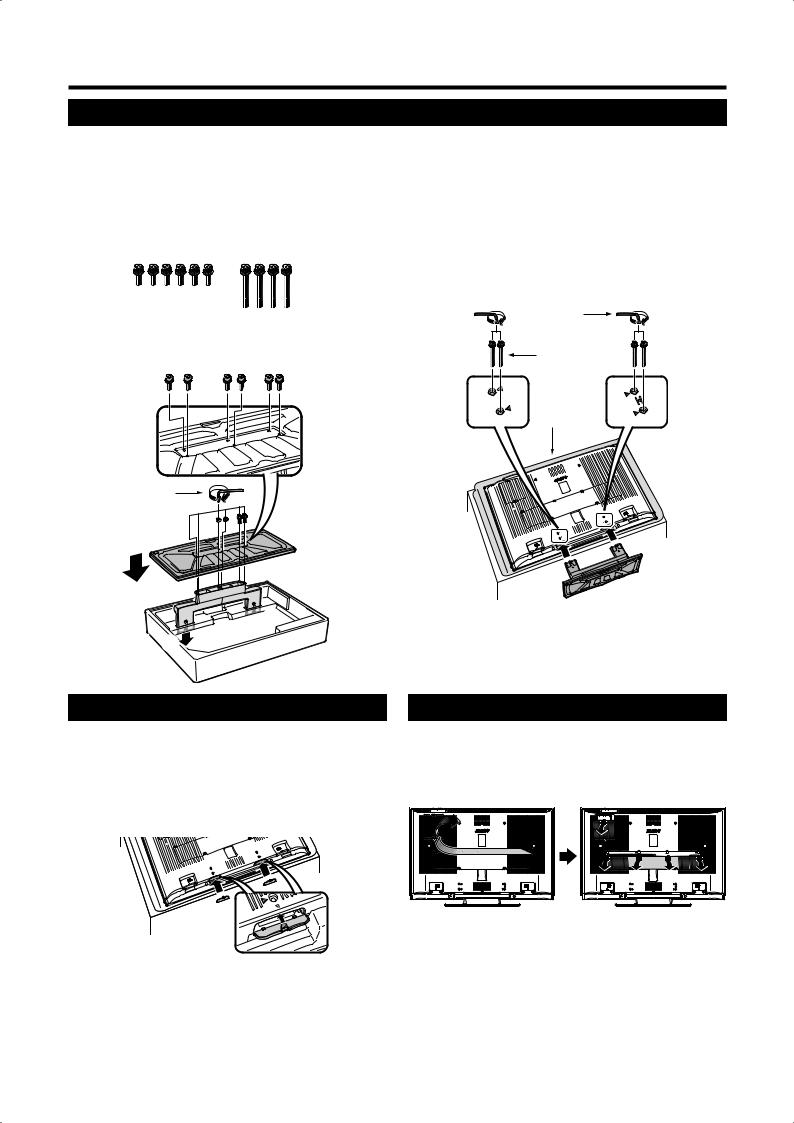
Attaching the speaker unit
•Before attaching (or detaching) the speaker unit, unplug the AC cord from the AC INPUT terminal.
•Before performing work spread cushioning over the base area to lay the TV on. This will prevent it from being damaged.
1Confirm that there are 4 screws and a screwdriver supplied with the speaker unit.
2Insert the projections on the speaker unit into the corresponding slots on the TV, then fasten the screws.
Insert and tighten the 4 screws with the screwdriver in the order of 1, 2, 3 and 4.
Screwdriver
Screw
3 |
|
|
|
|
|
|
1 |
2 |
|
|
|
|
|
|
|
4 |
|
|
|
|
|
|
|
|
|
|
|
|
|
|
|||||
|
|
|
|
|
|
|
|
|
|
|
|
||||||
|
|
|
|
|
|
|
|
|
|
|
|
|
|
|
|
|
|
|
|
|
|
|
|
|
|
|
|
|
|
|
|
|
|
|
|
Soft cushion
3Connect the ends of the cables to the speaker terminals as shown.
Connect the leads to the speaker terminals of the same colour.
Black Red
Red
Black 
NOTE
•To detach the speaker unit, perform the steps in reverse order.
 3
3
Preparation
Attaching the stand unit
•Before attaching (or detaching) the stand, unplug the AC cord from the AC INPUT terminal.
•Before performing work spread cushioning over the base area to lay the TV on. This will prevent it from being damaged.
CAUTION
•Attach the stand in the correct direction.
•Be sure to follow the instructions. Incorrect installation of the stand may result in the TV falling over.
1Confirm that there are 10 screws (6 short screws and 4 long screws) with the stand unit.
2Attach the supporting post for the stand unit onto the base using the box for the stand as shown.
Hex key |
3 |
Short screw 

2
 1
1 

1
31Insert the stand into the openings on the bottom of the TV. (Hold the stand so it will not drop from the edge of the base area.)
2Insert and tighten the 4 long screws into the 4 holes on the rear of the TV.
|
Hex key |
2 |
Long screw 2 |
|
Soft |
|
cushion |
1
Detaching the stand unit
1Repeat steps as explained in Attaching the stand unit in reverse order.
2Attach the stand hole covers.
(Align the tabs of the covers with the holes on the TV, and press until they lock into place.)
Removing the terminal cover
Before making any connections, remove the protective adhesive tape from the cover.
Then press down on the upper hooks and remove the rear terminal cover towards you.
 4
4
Preparation
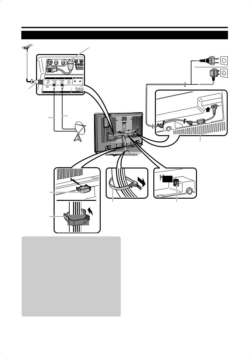
Setting the TV
Standard DIN45325 plug (IEC |
Connected at |
|||||||||
169-2) 75 q coaxial cable |
the factory * |
|||||||||
|
|
|
|
|
|
|
|
|
|
|
|
|
|
|
|
|
|
|
|
|
|
|
|
|
|
|
|
|
|
|
|
|
|
|
|
|
|
|
|
|
|
|
|
|
|
|
|
|
|
|
|
|
|
|
|
|
|
|
|
|
|
|
|
|
|
|
|
|
|
|
|
|
|
|
|
|
|
|
|
|
|
|
|
|
|
|
|
|
|
|
|
|
|
|
|
|
|
|
|
|
|
|
|
|
|
|
|
|
|
ANT 2
AC cord
ANT |
|
ANT SAT 1 ** |
|
||
SAT 2 |
|
|
Place the TV close to the AC outlet, and keep the power plug within reach.
(For Europe, except U.K. and Eire)
(For U.K. and Eire)
* Do not disconnect this cable |
|
unless otherwise instructed. |
Ferrite core* |
** When making the satellite |
|
connection, make sure that |
|
ANT SAT 1 takes priority, and |
|
do not connect ANT SAT 2 |
|
alone. |
|
Cable clamp (large)
Cable tie |
Cable clamp (small) |
Bundle the cables with the clamp.
Antenna
Connect the antenna cable from your antenna- /cable socket or the (room-/roof) antenna for antenna input terminal on the back of your TV set to receive digitally/terrestrially broadcast stations.
An indoor antenna can also be used under good reception conditions. Passive and active room antennas are offered commercially. In an active antenna its power is supplied via the antenna input terminal.
The supply voltage (5V) must be correspondingly set under “Allow switching voltage”. (Page 35)
* Ferrite Core
The Ferrite Core should be permanently attached and never removed from the AC cord.
Setting the TV on the wall
•This TV should be mounted on the wall only with the wall mount bracket available from SHARP. (Page 59) The use of other wall mount brackets may result in an unstable installation and may cause serious injuries.
•When you use the AN-52AG4 (SHARP) wall mount bracket, set the angle of the TV to 0° or 5°. Do not set the angle to more than 10°.
•Installing the LCD Colour TV requires special skill that should only be performed by qualified service personnel. Customers should not attempt to do the work themselves. SHARP bears no responsibility for improper mounting or mounting that results in accident or injury.
•You can ask a qualified service personnel about using an optional bracket to mount the TV to the wall.
 5
5
Preparation
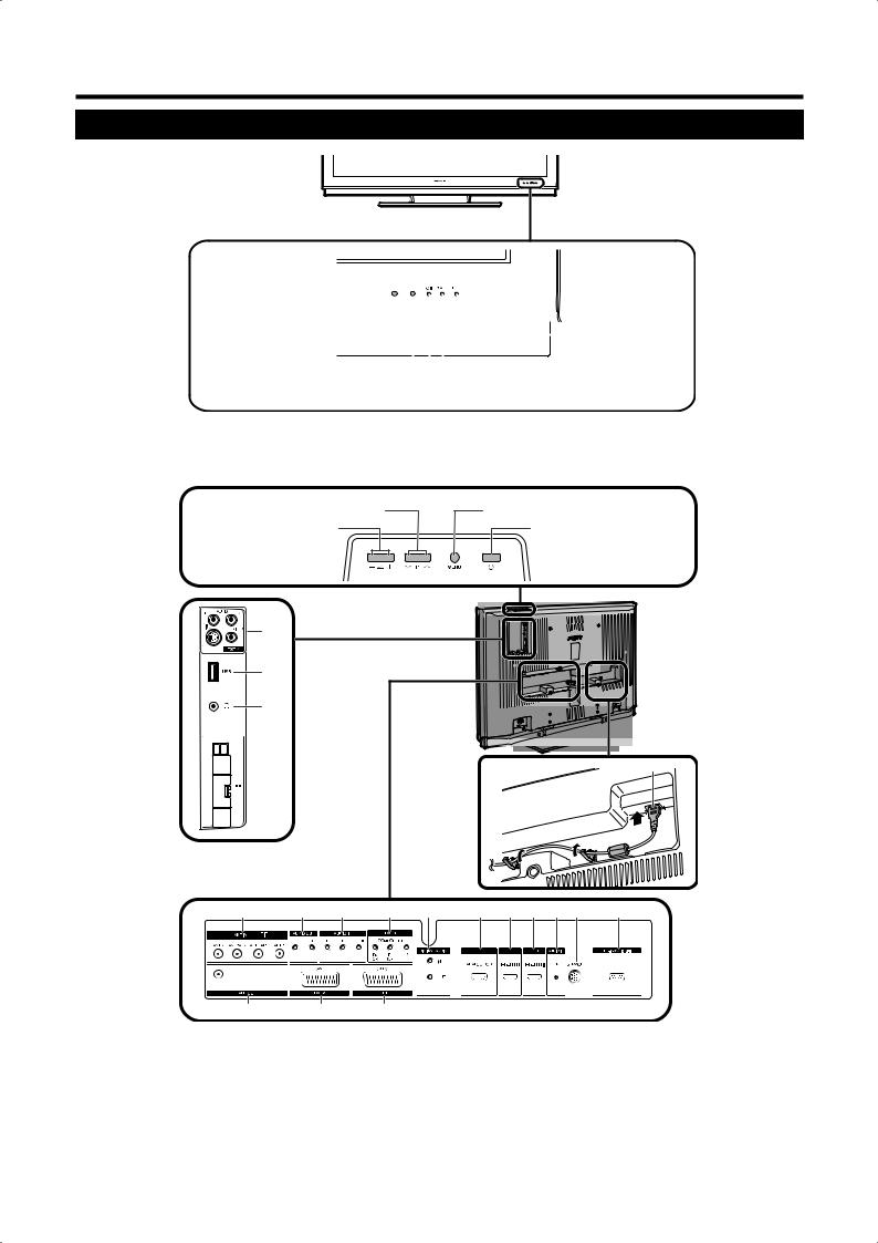
TV (Front view)
Remote control censor |
|
|
|
|
|
|
|
|
|
|
|
HDD indicator |
|
|
|
|
|
|
|
|
|
|
|
||||
|
|
|
|
|
|
|
|
|
|||||
|
|
|
|
|
|
|
|
|
|||||
OPC censor |
|
|
|
|
|
|
|
|
|
|
|
|
|
|
|
|
|
|
|
|
|
|
|
STATUS indicator |
|||
|
|
|
|
|
|
|
|
|
|
|
|||
|
|
|
|
|
|
|
|
||||||
|
|
|
|
|
|
|
|
||||||
|
|
|
|
|
|
|
|
|
|
|
|
|
B(Standby/On) |
|
|
|
|
|
|
|
|
|
|
|
|
|
indicator |
See page 12 for indictor status. |
|
|
|
|
|
|
|
||||||
|
|
|
|
|
|
|
|
||||||
TV (Rear view) |
|
|
|
|
|
|
|
||||||
P (r/s) |
|
|
MENU button |
||||||||||
Programme [channel] buttons |
|
|
|||||||||||
i(k/l) |
|
|
a(Power) button |
||||||||||
|
|
|
|
|
|
|
|||||||
Volume buttons
1 *
2
3
19


 4 **
4 **
5 |
6 |
7 |
8 |
9 |
10 |
11 |
12 |
13 |
14 |
15 |
16 17 18
1 |
EXT 4 terminals |
5 |
ANT IN terminals |
16 |
ANT OUT terminal |
|
|
* Do not connect S-VIDEO and VIDEO at |
6 |
AUDIO OUT terminals |
17 |
EXT 2 (AV) terminal |
|
|
the same time. |
7 |
AUDIO IN terminals |
18 |
EXT 1 (RGB) terminal |
|
|
|
8 |
EXT 3 |
(COMPONENT) terminals |
|
|
2 |
USB terminal |
9 |
DIGITAL AUDIO terminals |
19 |
AC INPUT terminal |
|
3 |
Headphones |
10 |
EXT 7 |
(ANALOG RGB) terminal |
|
|
4 |
COMMON INTERFACE slot (g2) |
11 |
EXT 5 |
(HDMI) terminal |
|
|
|
**Remove the cover when inserting the CI |
12 |
EXT 6 |
(HDMI) terminal |
|
|
|
Module. |
13 |
AUDIO IN (L/R) jack |
|
|
|
|
|
14 |
SERVICE socket |
|
|
|
|
|
15 |
RS-232C terminal |
|
|
|
 6
6
Preparation
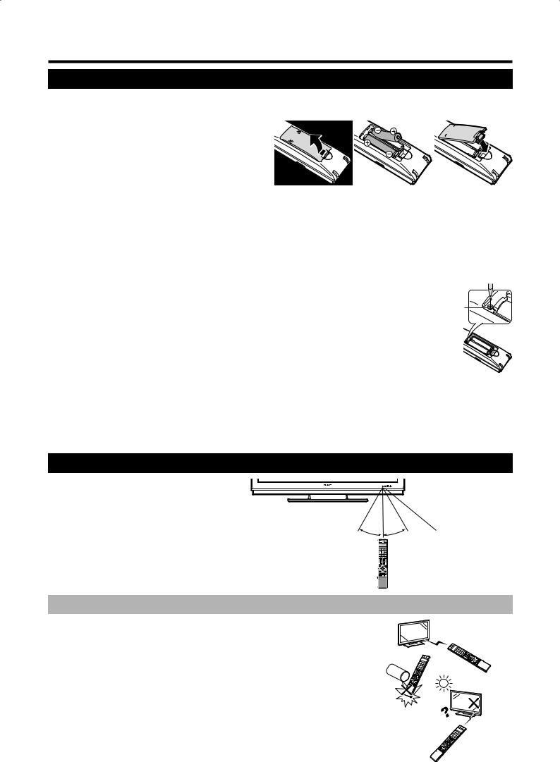
Inserting the batteries
Before using the TV for the first time, insert two “AAA” size batteries (supplied). When the batteries become depleted and the remote control unit fails to operate, replace the batteries with new “AAA” size batteries.
1
2
3
Open the battery cover.
Insert two supplied “AAA” alkaline size batteries.
•Place batteries with their terminals corresponding to the (k) and (l) indications in the battery compartment.
Close the battery cover.
CAUTION
Improper use of batteries can result in chemical leakage or explosion. Be sure to follow the instructions below.
•Do not mix batteries of different types. Different types of batteries have different characteristics.
•Do not mix old and new batteries. Mixing old and new batteries can shorten the life of new batteries or cause chemical leakage in old batteries.
•Remove batteries as soon as they have worn out. Chemicals that leak from batteries can cause a rash. If you find any chemical leakage, wipe thoroughly with a cloth.
•When replacing the batteries, use alkaline batteries instead of manganese ones.
•Do not overuse the light-up function of the LIGHT Dbutton, doing so may shorten the battery life. Replace the batteries
when the light on the LCD window or the light-up function becomes weak or when the window becomes blurry.
• Do not continue to use the remote control unit with the batteries running low. This may result in |
RESET |
error message or malfunction. Should this happen replace the batteries and leave it unused for |
button |
a while. Otherwise, you may open the rear battery cover and press the RESET button. When |
|
you press the RESET button, your Universal remote control settings will be deleted. |
|
• The remote control unit has a internal memory of external devices. In order not to lose the |
|
data, replace the batteries quickly. If the manufacturer code is initialised and lost, you can input |
|
the manufacturer code again. (See page 55.) |
|
•The batteries supplied with this product may have a shorter life expectancy due to storage conditions.
•If you will not be using the remote control unit for an extended period of time, remove the batteries from it.
Note on disposing batteries:
The batteries provided contain no harmful materials such as cadmium, lead or mercury.
Regulations concerning used batteries stipulate that batteries may no longer be thrown out with the household rubbish. Deposit any used batteries free of charge into the designated collection containers set up at commercial businesses.
Using the remote control unit
Use the remote control unit by pointing it
towards the remote control sensor. Objects between the remote control unit and sensor
may prevent proper operation.
5 m
30° |
30° |
Remote control censor |
Cautions regarding the remote control unit
•Do not expose the remote control unit to shock.
In addition, do not expose the remote control unit to liquids, and do not place in an area
with high humidity.
• Do not install or place the remote control unit under direct sunlight. The heat may cause deformation of the unit.
• The remote control unit may not work properly if the remote control sensor of the TV is under direct sunlight or strong lighting. In such case, change the angle of the lighting or TV, or operate the remote control unit closer to the remote control sensor.
 7
7
Preparation
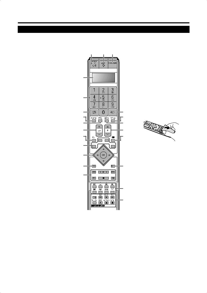
Remote control unit
NOTE
•The symbols 8, 9and 0indicate that the buttons become available in respective operating mode when using as a universal remote control.
1B(TV Standby/On) (Page 12)
2LIGHT D890
When pressed, buttons that are frequently used (P r/s, ik/l, 0 - 9 numeric buttons, Aand b) will light. The lighting will turn off if no operations are performed within about 5 seconds. This button is used for performing operations in low-light situations.
3FUNCTION 890
Press this button briefly (for more than 0.2 second), and the remote control switches for DVD, SetTopBox or VCR operation and currently controlled devices will be indicated in the LCD window.
See page 55 for how to use this unit as a universal remote control.
4LCD window 890
This screen shows which device you are currently controlling. (TV, DVD, STB or VCR).
50 - 9 numeric buttons 9
Set the channel.
Enter desired numbers or letters as if on a mobile keypad.
Set the page in teletext mode.
6A(Flashback)
Press to return to the previous image in normal viewing mode.
7RADIO
Switch between RADIO and TV mode.
8EPG
Display the EPG screen.
9i(k/l) (Volume)
Increase/decrease TV volume.
10e(Mute)
TV sound on/off
11Colour (RED/GREEN/YELLOW/BLUE) buttons
In Teletext mode: Select a page. (Page 40) When no other menu screen is active, pressing one of the coloured buttons will initiate the following action.
RED
Opens the DR archive. (Page 44)
GREEN
Opens the teletext subtitle size selection screen.
YELLOW
Calls last viewed station/external source.
BLUE
Displays the programme info screen.
On the menu screen, the coloured buttons are used to select correspondingly the coloured items on the screen.
1 |
2 |
3 |
4 |
|
|
5 |
|
|
6 |
|
15 |
7 |
|
16 |
8 |
|
17 |
9 |
|
18 |
10 |
|
19 |
11 |
|
|
12 |
|
|
13 |
|
20 |
14 |
|
|
15b(External sources)
Select an external source. Press and move with a/b.
16MENU 8
TV: Menu screen on/off. DVD: Title menu on/off.
17INFO
Press to open the Index menu. (Page 31) Teletext: Display Teletext page 100.
18P (r/s) 890
Select the TV channel.
In analogue TV mode, external sources can also be selected.
19m(Teletext)
Select teletext. (Page 39)
20BACK
Return to the previous menu screen.
21Buttons for teletext and other useful features
Flip open the remote control cover on the front.
k(Reveal hidden Teletext) (Page 40)
[(Subtitle for Teletext)
Subtitle on/off. (Page 40)
v(Top/Bottom/Full)
Set the area of magnification in analogue teletext mode. (Page 40)
3(Freeze/Hold) (Page 40)
1(Subpage) (Page 40)
PIP
Press to enter Picture-in-picture mode. (Page 23)
|
DEMO |
|
21 |
Demonstrate the 100 Hz effects in a dual |
|
screen format. (Page 32) |
||
|
f(Wide modes) |
|
22 |
Select the wide mode. (Page 39) |
|
22 AQUOS LINK buttons 80 |
||
|
If external equipment such as a AQUOS |
|
|
BD Player is connected via HDMI cables |
|
12 a/b/c/d (Cursor) 8 |
and is AQUOS LINK compatible, you can |
|
use these AQUOS LINK buttons. See |
||
Select a desired item on the setting |
||
page 19 for details. |
||
screen. |
||
In DVD or VCR mode, press OPTION to |
||
If no other menu screen is active, press |
||
pause the picture. |
||
a/b, and move the picture up/down with |
||
Not available when operating STB except |
||
a/b/c/d. |
||
powering on the device. |
||
OK 89 |
||
|
TV/DVD/STB: Execute a command within the menu screen.
TV: Display the station list or favourite list when no other menu screen is running.
13END
Exit the menu screen.
If menu screen is not active, pressing this button displays programme information.
14Buttons for HDD operation
These are used for basic HDD recording/ playback operation integrated with this TV.
 8
8
Initial installation
Initial installation overview
Follow the below steps one by one when using the TV for the first time. Some steps may not be necessary depending on your TV installation and connection.
n Connect the AC cord (Page 5)
o Connect antenna (Page 5)
Analogue/DVB-C/DVB-T antenna:
Plug the antenna of antenna system, cable system, or room antenna to ANT 2. Cable is already connected between ANT 1 and ANT OUT at the factory.
Satellite antenna:
Connect an antenna plug, e.g., from the antenna change over switch or from the twin-LNC of the satellite system to ANT SAT 1 and ANT SAT 2.
When connecting only one SAT antenna cable, connect it to ANT SAT 1.
p Prepare remote control unit (Page 7)
q Turn on the TV power (Page 12)
r Conduct initial auto installation (Page 10)
s Connect external devices (Pages 14-18)
If desired connect external devices such as a DVD recorder here.
t Connect sound components (Page 22)
If desired connect sound components (amplifier/speakers) here.
u Insert CA Card (Page 28)
When using a CI Module and a CA Card to receive coded stations, insert CA Card as instructed.
v Adjust DVB-T antenna (Page 11)
If necessary position or align DVB-T antenna.
 9
9
Initial installation
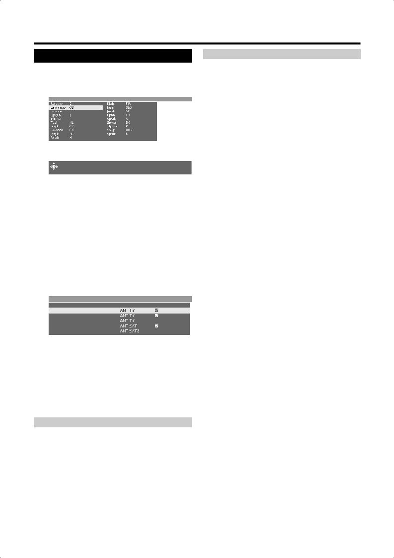
Initial installation wizard
When the TV powers on for the first time after purchase, the initial auto installation wizard appears. Follow the menus and make the necessary settings one after another.
Initial installation -> Language
 Proceed
NOTE
•You can repeat this installation process by conducting the “Repeat initial installation” command. Press INFO, the option is located in the third line from the top.
Buttons to be used: a/b/c/d:
Move the cursor and select the settings.
OK:
Press to confirm and proceed to the next step.
YELLOW:
In some screens you can select or deselect items with YELLOW. When an item is selected, it is marked with .
Initial installation -> Connect antenna cable(s)
Antenna cable(s) for: |
to antenna socket(s): |
Antenna/cable (analogue) |
|
DVB-T |
|
DVB-C |
|
DVB-S (cable 1) |
|
DVB-S (cable 2) |
|
BACK:
Press to go back one step.
END:
If this icon is visible, you can exit the wizard.
Table of setting options in initial installation wizard
There are numerous settings in the initial installation wizard. When in doubt, refer to the table below so you don’t get overwhelmed.
Items |
Explanation |
|
|
|
|
Language |
Select the language. |
|
|
|
|
|
Antenna/cable (analogue): analogue stations |
|
Connect |
via cable/antenna |
|
DVB-T: digital, terrestrial stations |
||
antenna |
||
DVB-C: digital stations via cable |
||
cable(s) |
||
DVB-S (cable 1): digital stations via satellite |
||
|
||
|
DVB-S (cable 2): digital stations via satellite |
|
|
|
|
Antenna DVB-T |
If you are using an active antenna, then select |
|
yes (5V) for the antenna power supply. |
||
|
||
|
|
Items |
Explanation |
|
|
|
|
|
The conventional settings will be derived from |
|
|
the selection of set location. Only change this |
|
|
if you know other symbol rates and modulation |
|
Antenna |
types or if you have to specify the network ID for |
|
your cable network (information available from |
||
DVB-C |
||
your cable network provider). If you want to run |
||
|
||
|
the station search independently of the channel |
|
|
grid, select frequency search for the search |
|
|
method. |
|
|
|
|
|
Select which satellite(s) you receive from a list. |
|
Antenna |
For more than one satellite, select the type of |
|
your changeover switch or communal satellite |
||
DVB-S |
||
system additionally. Ask your dealer in this |
||
|
||
|
regard. |
|
|
|
|
|
Specify here whether the high band of the |
|
High band |
selected satellite is to be searched in addition to |
|
|
the low band. |
|
|
|
|
|
Normally, you do not need to change the values |
|
LNB |
for high and low band, unless the LNC (LNB) of |
|
your satellite system uses a different oscillator |
||
frequencies |
||
frequency (important for the frequency display). |
||
Low Band/High |
||
After you have made these settings, you should |
||
Band |
||
receive the picture and sound of the selected |
||
|
||
|
satellites (only with Astra1 and HOTBIRD). |
|
|
|
|
|
The symbol rates are specified by the satellite |
|
Symbol rates |
provider and do not normally need to be |
|
|
changed. |
|
|
|
|
|
Select the signal source from a list, the station |
|
|
of which is to be at the top of your station list |
|
Favoured signal |
(starting with station slot 1). |
|
• If you want to use the AV Link function with an |
||
source |
externally connected recorder, the analogue |
|
|
||
|
stations have to be between station slot 1 and |
|
|
99. |
|
|
|
|
|
Start the automatic station search with OK. First |
|
|
TV stations, then radio stations are searched |
|
|
for. The stations found in the automatic search |
|
|
are divided into the appropriate station blocks |
|
|
depending on the previously selected antenna |
|
|
cables (signal sources). Subsequently the |
|
Start search |
stations can only be re-sorted within these |
|
|
blocks. At the beginning of the station list |
|
|
you will find the block with the stations of the |
|
|
preferred signal source. |
|
|
Any mixed sorting of stations from different |
|
|
signal sources is only possible with the |
|
|
favourites list. |
|
|
|
|
|
In conclusion the connection wizard will start; |
|
|
with their help you can register and set your |
|
|
video devices or decoders, and connect them to |
|
Connecting |
the TV set. DVD players and DVD recorders are |
|
additional |
already registered at the factory. |
|
devices |
You can start the connection wizard manually |
|
|
later and add new devices. Further information |
|
|
is available on page 15 (Connection wizard) and |
|
|
page 22 (Speaker/amplifier connection). |
|
|
|
|
Room antenna |
With good reception conditions a room antenna |
|
can be used for DVB-T (socket ANT2). |
||
|
||
|
|
|
|
Under less favorable reception conditions, it is |
|
|
advisable to use an active antenna which has to |
|
Active antenna |
be set accordingly in the initial installation or in |
|
the “TV Menu > Connections > Antenna DVB > |
||
|
||
|
Antenna DVB-T”. (See “Antenna DVB-T” on this |
|
|
page). |
|
|
|
|
Unidirectional |
If the location is outside of the normal |
|
transmission range then a directional antenna |
||
antenna |
||
can be used to improve reception quality. |
||
|
||
|
|
 10
10
Initial installation
Positioning/aligning DVB-T antenna
If you are receiving one or more DVB-T stations with picture and sound interference then you should change the installation location and alignment of the antenna. Ask your dealer to tell you which channels are used to broadcast the DVB-T stations in your region.
1
2
Prerequisite: In normal TV mode, with no other menu screen active, and a DVB-T station is received and selected.
Press MENU and the TV menu screen displays.
Press c/d to select “Setup”, and then press
OK.
3Press a/b to select “Stations”, and then press
OK.
Press a/b to select “Manual tune”, and then press OK.
TV menu -> Setup -> Stations |
|
|||||
Manual tune |
Change stations Select/change favourites |
Search wizard |
||||
|
|
|
|
|
|
|
Signal source |
Antenna/cable (analogue) DVB-T DVB-C DVB-S |
|||||
Channel |
E05 |
|
||||
Frequency |
177.50 MHz |
|
||||
Bandwidth |
7 MHz |
|
||||
Name |
12 Test |
|
||||
C/N 96 |
|
Level 99 |
|
|
|
|
•The signal source is already on DVB-T due to the station preselection.
4Position and align the antenna in such a manner that maximum values for C/N and Level are obtained.
5Press BLUE to start search.
Search for DVB-T stations one after another and compare values for C/N and Level.
Then position/align the antenna to the weakest station so that maximum values for C/N and Level are obtained.
6Thereafter perform an automatic search for all DVB-T stations.
Item |
Explanation |
Depending on the selected channel and country Bandwidth the associated bandwidth of 7 or 8 MHz will be set
automatically.
 11
11

Daily operation
Switching on/off
Turning on/off the power
Press aon the TV.
Switch it off by pressing aon the TV.
•However, please bear in mind that EPG data (electronic programme guide) will be lost, and programmed timer recordings will not be performed by the TV.
Standby mode
If the TV set is switched on, you can switch it to standby by pressing Bon the remote control.
Switching on from standby
From standby, press Bon the remote control or pressing any of the numeric buttons 0 - 9.
Or, switch on the TV set with OK, you can then see the station list and select a station.
Switching on the radio
From standby, press RADIO on the remote control.
TV indicator status
There are three indicators at the front of the TV. Refer to the table for each LED status.
Bindicator |
Status |
|
|
|
|
Off |
Power off |
|
|
|
|
Blue |
Power on |
|
|
|
|
Red |
Standby |
|
|
|
|
|
|
|
STATUS |
Status |
|
indicator |
||
|
||
|
|
|
Red |
On Timer is programmed. |
|
|
|
|
Red flashing |
Receiving remote control command |
|
|
|
|
Green |
HDD recording timer is programmed. |
|
|
|
|
Green flashing |
Receiving EPG data |
|
|
|
|
Orange |
Both HDD recording timer and On Timer are |
|
programmed. |
||
|
||
|
|
|
|
|
|
HDD indicator |
Status |
|
|
|
|
Red |
HDD recording in progress |
|
|
|
|
Green |
Archive playback or Time Shift recording in progress |
|
|
|
NOTE
•If you are not going to use this TV for a long period of time, be sure to remove the AC cord from the power outlet.
•Weak electric power is still consumed even when ais turned off.
Changing channels
With Pr/Ps:
Press Pr/Psto select channels.
•The station display with audio format displays briefly.
•If favourites are set, only the registered channels are selected with Pr/Ps. (Page 13)
•The symbols for the audio format is provided on page 13.
•If there are additional languages or DVB subtitles for DVB stations, its selections are shown under the station display. (Page 13)
|
With 0 - 9: |
|
12 |
Press |
0 - 9 to select channels. |
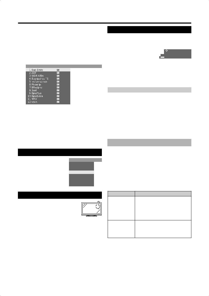
With station list:
1Press OK with no other menu screen active. (If favourites list is displayed instead, press RED.)
Station list
EXT3
EXT5
EXT6
2Press a/b/c/d or 0 - 9 to select the desired channel in the station list, and then press OK to tune in.
•Press RED to go to the favourites list.
•Press BLUE to sort the list according to “alphabetical” or “numerical”.
•If sorted alphabetically, enter the initial letters with 0 - 9 like on a mobile phone keypad. The first station for the specified letters is marked.
To delete, restore, move, and rename stations from the station list
While in the station list, press YELLOW (Change stations).
EDelete
Select a station to delete, and then press RED (Delete). Mark more stations with a/b/c/d or 0 - 9, if desired. Confirm with OK or cancel with
RED.
ERestore stations
To restore station(s) that you have already deleted, select a station to restore, and then press GREEN (Restore stations). Confirm with
OK.
•The restored station is sorted according to its signal source at the end of the respective signal block.
EMove
Select a station to move, and then press YELLOW (Move). Mark more stations with a/ b/c/d or 0 - 9, if desired. Press OK to finish marking.
Press a/b/c/d or 0 - 9 to select the position to move to. Confirm with OK or cancel with
YELLOW.
•Make sure to select the appropriate block of channels or destination when moving.
ERename
Select a station to rename, and then press BLUE (Rename). Press any of the numeric buttons 0 - 9 to select the desired character. Remember to press and toggle the numeric button quickly, for the transition to the next digit is rather quick. Repeat until the new name is fully spelt out. Confirm with OK or cancel with
BLUE.
•The name can be up to 9 characters.
•Available only in the analogue TV mode.
Daily operation
With the favourites lists:
You can save and select your favourite stations in 6 favourites lists (e.g. for multiple users). Each
favourites list can contain up to 99 stations. After initial installation, 10 stations from the station list are already stored in the first list. Change the favourites list to suit your requirements (see “Select/change favourites” on page 37).
1Press OK with no other menu screen active.
Favourites -> FavouriteList1
2Press RED to display the favourite list.
3Press 0 - 9 or a/b/c/d to select the desired station, and then press OK to register as a favourite.
RED: Back to the station list
GREEN: Scan all stations (as in slide show) of the currently selected favourites list. Press OK to end scanning.
YELLOW: Change the favourites list. (Page 37) c/d: Move to the previous/next favourites list.
Selecting external video source
Once the connection is made, press bto display the External Sources screen, and then press a/b to switch over to the appropriate external source with OK.
You can also select an external source via the station list.
External sources
VIDEO
DVD-REC
DVD
EXT3
EXT4
EXT5
EXT6
EXT7
Operation without remote control
This function is useful when there is no remote control within your reach.
1Press MENU briefly to display the
direct control screen.
•You can adjust the following items: “Operating mode”, “External sources”, “Brightness”, “Contrast”, “Wide modes” and “Service”.
•“Service” is the item reserved only for service personnel.
2Select the item by pressing P r/s.
3Select or adjust by pressing ik/l.
NOTE
•The direct control menu screen will disappear if left unattended for several seconds.
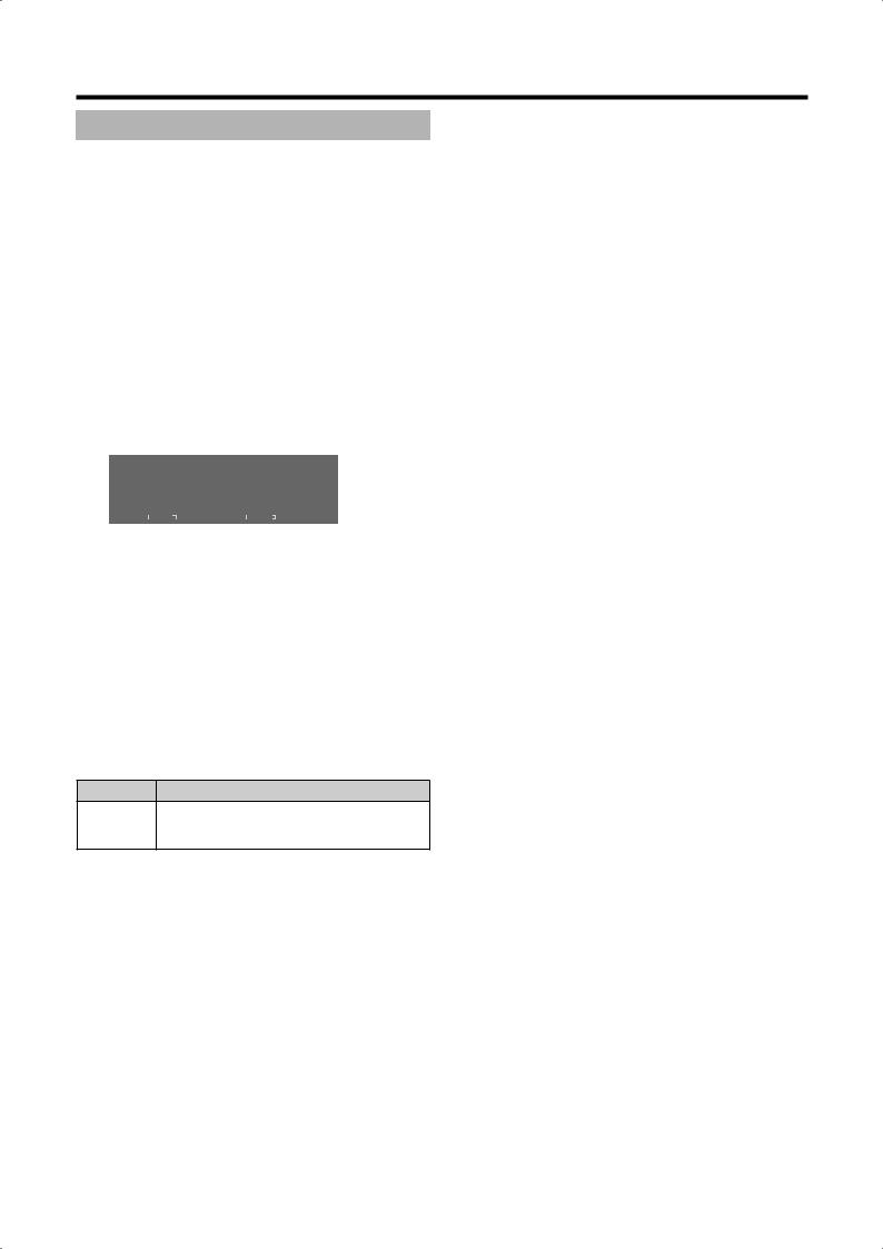
Status display
Press END, a status display appears for a few seconds.
1 Das Erste |
Dolby D |
|
Toskana |
14:31
Wake up Mon-Fri 14:50

 Language/sound selection
m DVB subtitles
•In the top line you can see the number and name of the station, the title of the programme and the audio format. The time and, if activated, the alarm time/ alarm and switch-off time are displayed. Go to “TV menu > Setup > Miscellaneous > On-screen displays” for how to customise the settings for the status display.
Audio format |
Description |
|
|
|
|
Mono |
Mono audio transmission analogue |
|
|
|
|
2-sound |
Two-sound transmission (Sound1/Sound2) |
|
analogue |
||
|
||
|
|
|
Stereo |
Stereo sound transmission analogue or |
|
digital (PCM) |
||
|
||
|
|
|
Dolby D |
Dolby Digital sound transmission (DD) |
|
|
|
|
MPEG |
MPEG sound transmission |
|
|
|
|
, , , , , |
These symbols refer to the number of audio |
|
, , , |
signals and optimum position/number of |
|
speakers (upper edge facing front). |
||
|
||
|
|
Additional DVB options
In the status display additional selection possibilities can be offered for specific programmes depending on the DVB programme provider.
Press one of the coloured buttons or m during the status display, and the associated selection menu appears.
RED: Channel selection for multi-channel providers GREEN: Language/audio selection
m: DVB subtitles/teletext
•The selection menus are only available as long as the status display is shown.
Item |
Description |
The subtitle selection refers exclusively to DVB subtitles and is not offered by all stations. Many stations only transmit
DVB subtitles subtitles by teletext.
You can make general settings for DVB subtitles under “TV menu > Setup > Miscellaneous > DVB subtitles”.
The selection line is automatically displayed briefly, if a new programme begins with
New programme options that are different from those of the previous programme, or if you switch to a different station.
 13
13
Connecting external devices
The TV’s integrated Connection wizard helps you connect new external devices and make cable changes. Before actually connecting the external device, run the Connection wizard and register the equipment to be connected.
EBefore connecting ...
Carefully read the operation manual of each external device for possible connection types. This also helps you get the best possible audiovisual quality to maximise the potential of the TV set and the connected device. Make a note of the type of your connection before running the wizard.
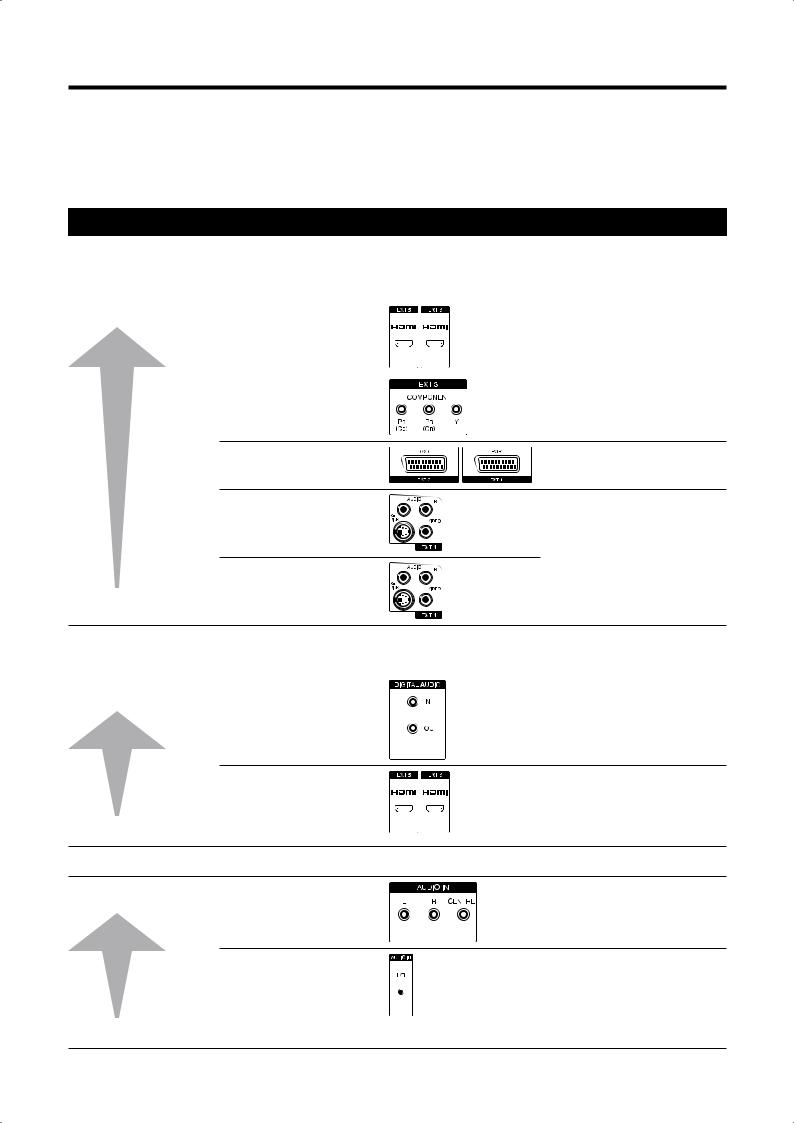
Note on higher picture and sound quality
Higher quality is attained in ascending order. Refer to the manual of the device to be connected for the best possible connection.
EVideo terminals |
|
Remarks |
Higher Quality |
1 HDMI (EXT 5 or 6) |
When using an HDMI/DVI |
|
|
conversion cable, audio must be |
|
|
fed in separately. |
|
|
|
|
2 COMPONENT (EXT 3) |
|
3 Euro SCART (EXT 1 or 2)
4 S-VIDEO (EXT 4)
|
Do not connect S-VIDEO and |
5 VIDEO (EXT 4) |
VIDEO at the same time. |
|
Standard Quality
EAudio terminals
Digital audio connection |
Remarks |
|
Higher Quality |
1 DIGITAL AUDIO IN/OUT |
In this connection you must |
|
|
specify the terminal to which the |
|
|
|
audio is fed. (Page 35) When using HDMI (EXT 5 or
6), the HDMI audio input takes priority.
2 HDMI (EXT 5 or 6)
Standard Quality
When using an HDMI/DVI conversion cable, audio must be fed in separately.
DOLBY DIGITAL signals are not played back.
Analogue audio connection
Higher Quality |
1 AUDIO IN (L-R-CENTRE) |
2 AUDIO IN (L/R)
Standard Quality
 14
14

Connecting external devices
Connection wizard
The integrated Connection wizard shows you which terminal you should connect your equipment to. Connect the equipment according to the diagram and follow the messages one after the other.
NOTE
•New devices should not be connected until they have been registered in the connection wizard.
1Press MENU and the TV menu screen displays.
2Press c/d to select “Connections”, and then press b to move down.
3Press a/b to select “AV setup”, and then press
OK.
• The connection wizard screen displays.
4Press OK. The screen shows a default screen, which may differ from the actual connection. Press OK to proceed.
Default screen
AV setup
Connection wizard
Now the TV set assumes that you have connected the following equipment:
|
|
|
|
|
|
|
|
|
|
|
|
|
|
|
|
|
|
|
|
|
|
|
|
|
|
|
|
EXT4 |
EXT1 |
|
EXT2 |
|
EXT3 |
EXT5 |
EXT6 |
||||||
5The AV equipment selection screen opens. Select device(s) to connect with a/b, and then press YELLOW to mark. A marked device is indicated with . For example, if connecting DVD recorder with HDMI terminal to the TV, select “HDMI/DVI” and then press YELLOW to register. You can connect other devices in the same way.
AV setup -> AV equipment selection
|
DVD |
DVD player |
|
DVD • |
DVD recorder |
|
VCR |
Video recorder |
|
SAT |
Satellite receiver |
|
STB |
SetTopBox/dBox |
|
Decoder |
Decoder |
|
Camera |
Camcorder/camera |
|
AV |
Other device(s) to EXT1/2/4 |
|
COMP.IN |
Device to EXT3 |
|
HDMI/DVI |
Device to EXT5 |
|
HDMI/DVI |
Device to EXT6 |
Connection wizard
Specify all new AV devices to be connected and all connection changes to the existing devices here.
6Next, the connection diagram shows how to connect the new or preset devices to the rear terminals. Press OK to proceed.
•If you specify a decoder for connection, you will be directed to “Select decoder station(s)” submenu.
7Specify the signal type for the terminal. If you are not sure, select the automatic setting.
8Follow the instructions on the screen for the rest of the process.
Items |
Explanation |
|
|
|
The signal type of the devices that can be |
|
connected can vary greatly. If you are not sure, |
Connections |
leave the setting for “Signal” on “Automatic |
and signal |
CVBS/YC” (e.g. for DVD Player/Recorder) or |
|
“Autom.-VHS/SVHS” (e.g. VCR), otherwise select |
|
the right signal type. |
|
|
|
If the picture from a connected device is to be |
|
displayed immediately on the TV set during |
|
playback, select “yes”. A switching voltage is |
|
allowed so that you do not have to switch over |
Immediate |
manually to see the picture of the connected |
playback |
device. (See the operating manual for the |
|
connected reproduction device.) |
|
When playing from AV Link devices, the picture is |
|
always displayed immediately, regardless of the |
|
setting. |
|
|
|
Select the AV socket to which the device of |
|
which you want to hear the digital sound is |
Assign digital |
connected. Connect the digital output of the |
audio input |
external device to the digital input of the TV set. |
|
(Page 22) If a device with digital audio is not |
|
connected then select “no”. |
|
|
 15
15

Connecting external devices
HDMI connection
(Optional audio |
(Optional audio |
connection) |
connection) |
The HDMI connections (High Definition Multimedia Interface) permit digital video and audio transmission via a connection cable from a player.
The digital picture and sound data are transmitted without data compression and therefore lose none of their quality. Analogue/digital conversion is no longer necessary in the connected devices, which also would result in quality losses.
HDMI/DVI conversion
Using a DVI/HDMI adapter cable, the digital video signals of a DVD or PC can also be played via the compatible HDMI connection. The sound must be fed in additionally.
HDMI and DVI both use the same HDCP copy protection method.
Connecting the HDMI device
In “Connection wizard > AV equipment selection”, select “HDMI/DVI”, and connect the device accordingly.
•If an HDMI/DVI conversion cable is used, audio signals must be fed separately to either DIGITAL AUDIO (IN) or analogue AUDIO IN (L/R).
NOTE
•Video noise may occur depending on the type of HDMI cable used. Make sure to use a certified HDMI cable.
•When playing an HDMI image, the best possible format for the picture will be detected and set automatically.
Supported video signals:
VGA, 576i, 576p, 480i, 480p, 720p, 1080i, 1080p See page 18 for PC signal compatibility.
If a connected HDMI device is AQUOS LINK compatible, you can take advantage of versatile functions using the AQUOS LINK buttons on the remote control.
See pages 19 - 22 for details.
VGA/XGA connection (PC/
SetTopBox)
You can connect a PC or a SetTopBox (STB) to the EXT 7 (ANALOG RGB) terminal and thus use the screen of the TV set as an output device.
When connecting the PC, set the PC’s output resolutions according to the capabilities of the PC. For details, see page 18 for PC signal compatibility.
When connecting a SetTopBox, set the following screen resolutions according to the capabilities of the SetTopBox:
Supported video signals (for STB):
576i, 576p, 480i, 480p, 720p, 1080i
Connecting
Connect the device to EXT 7 via the VGA cable. See page 22 for the sound connection.
Registration in the connection wizard is not necessary.
Adjusting the geometry
Using this function, you can adjust the horizontal/ vertical position of the picture. (Page 38)
Setting the colour standard
1Press MENU and the TV menu screen displays.
2Press c/d to select “Picture”, and then press b to move down.
3Press a/b to select “Colour standard”, and then press b to move down.
4Press c/d to select “RGB” for PC, and “Ycc” (in rare cases, “Ypp” or “RGB”) for STB, and then press OK.
 16
16
Connecting external devices
Audio connection
Analogue audio:
Connect the analogue audio signal from the PC or the SetTopBox via stereo cable to the AUDIO IN (L/R) jack on the TV set.
•The sound is played via the speakers connected to the TV set or a speaker system.
Digital audio:
•An external digital audio signal can be reproduced via the integrated Dolby Digital Decoder or via an externally connected digital audio amplifier.
1 Connect the digital audio signal from the PC or the SetTop-Box via a simple cinch cable to the DIGITAL AUDIO (IN) socket on the TV set.
2Then assign the digital audio input in “TV menu > Connections > Miscellaneous > Assign digital audio input”.
For an external digital audio amplifier:
1Prerequisite: External audio amplifier is already connected. (Page 22)
2Feed the digital audio signal of the DIGITAL AUDIO (OUT) socket on the TV set to the external amplifier.
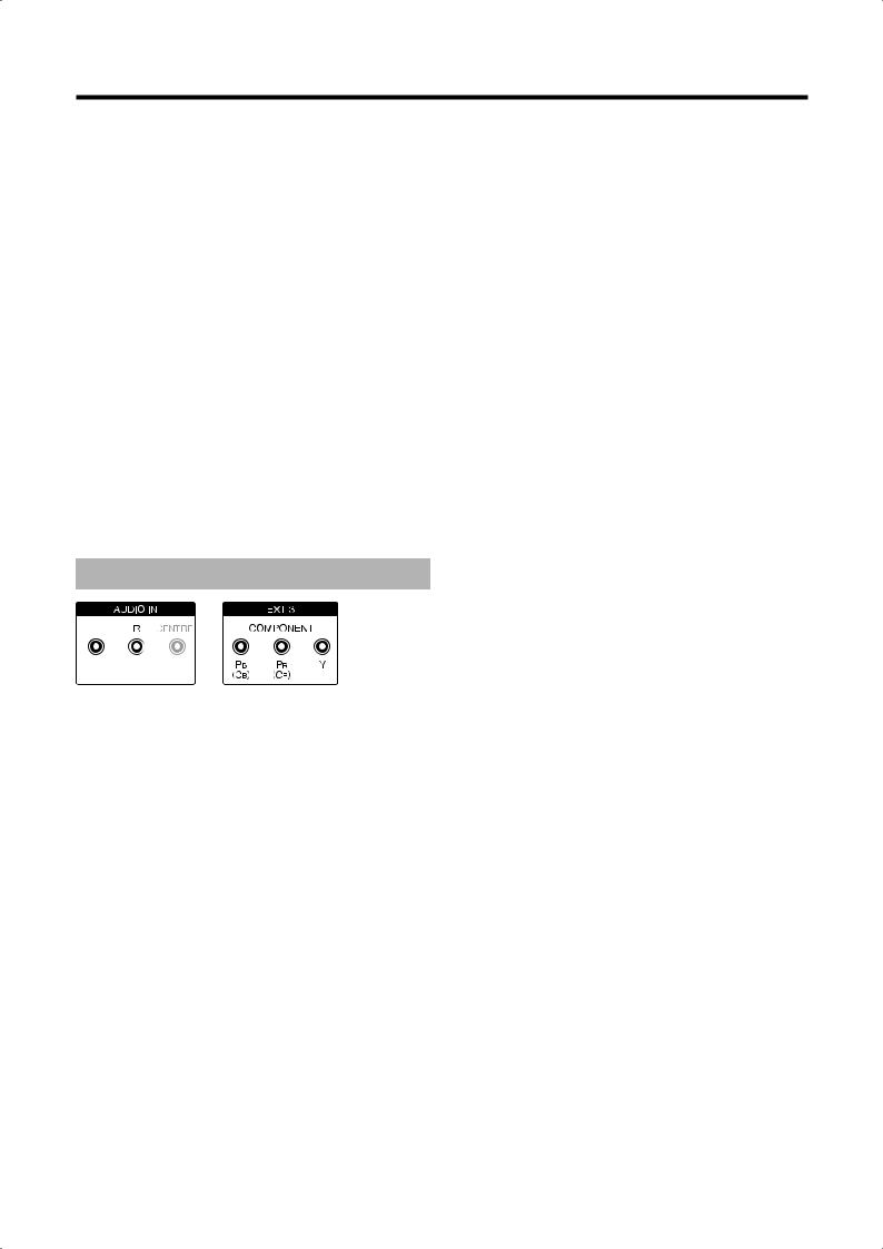
Component connection (EXT3)
DVD players/recorders with component video connections can also be connected to EXT 3 (COMPONENT) of the TV set instead of to the SCART sockets.
The connecting cable with three cinch plugs transmits the picture information with better quality than a SCART cable. You need an additional cable for audio transmission.
The basic procedure of setting up a component connection (cable connection and audio connection) is the same as explained in the previous section, “VGA/ XGA connection (PC/SetTopBox)”, except:
When adjusting the parameters in “Signal type at socket EXT3”, select “Automatic” if you are not sure. Read the operation manual of the external device for other options.
 17
17

Connecting external devices
PC compatibility chart
Resolution |
Horizontal |
Vertical |
Analogue (D- |
Digital (HDMI) |
VESA Standard |
||
Frequency |
Frequency |
Sub) |
|||||
|
|
|
|
||||
|
|
|
|
|
|
|
|
VGA |
640 g 480 |
31.5 kHz |
60 Hz |
|
|
g |
|
|
|
|
|
|
|
|
|
SVGA |
800 g 600 |
37.9 kHz |
60 Hz |
|
|
g |
|
|
|
|
|
|
|
|
|
XGA |
1024 g 768 |
48.4 kHz |
60 Hz |
|
|
g |
|
|
|
|
|
|
|
|
|
SXGA |
1280 g 1024 |
64.0 kHz |
60 Hz |
|
|
g |
|
|
|
|
|
|
|
|
|
FULL HD |
1920 g 1080 |
67.5 kHz |
60 Hz |
|
|
|
|
VGA, SVGA, XGA and SXGA are registered trademarks of International Business Machines Corporation.
NOTE
•This TV has only limited PC compatibility, correct operation can only be guaranteed if the video card conforms exactly to the VESA 60Hz standard. Any variations from this standard will result in picture distortions.
 18
18
Loading...