


15L1U-LC
SHARP ELECTRONICS CORPORATION
Sharp Plaza, Mahwah, New Jersey 07430-2135
SHARP CORPORATION
ENGLISH
LC-15L1U
FRANÇAIS
|
|
|
LIQUID CRYSTAL TELEVISION |
ESPAÑOL |
|
TÉLÉVISEUR ACL |
|
|
TELEVISOR CON PANTALLA |
|
|
ÊS |
||
DE CRISTAL LÍQUIDO |
||
TELEVISOR DE CRISTAL |
PORTUGU |
|
|
||
LÍQUIDO |
|
|
OPERATION MANUAL |
|
|
|
||
MODE D’EMPLOI |
|
|
MANUAL DE OPERACIÓN |
|
|
MANUAL DE OPERAÇÃO |
|
Printed on 100% post-consumer recycled paper.
Imprimé sur 100% de papier recyclé.
Impreso en 100% de papel reciclado de postconsumo. Papel 100% Reciclado-Cuidado do Meio Ambiente.
Printed in Japan Imprimé au Japon Impreso en Japón Impresso no Japão
TINS-B124WJZZ 04P02-###
LC-15L1U
LIQUID CRYSTAL TELEVISION
ENGLISH
ENGLISH |
OPERATION MANUAL
IMPORTANT:
To aid reporting in case of loss or theft, please record the TV’s model and serial numbers in the space provided. The numbers are located at the rear of the TV.
Model No.:
Serial No.:
U.S.A. ONLY
IMPORTANT INFORMATION
WARNING: TO REDUCE THE RISK OF FIRE OR ELECTRIC SHOCK, DO NOT EXPOSE
THIS PRODUCT TO RAIN OR MOISTURE.
CAUTION
RISK OF ELECTRIC SHOCK
DO NOT OPEN
CAUTION: TO REDUCE THE RISK OF ELECTRIC SHOCK,
DO NOT REMOVE COVER (OR BACK). NO USER-SERVICEABLE PARTS INSIDE.
REFER SERVICING TO QUALIFIED SERVICE
PERSONNEL.
The lightning flash with arrowhead symbol, within an equilateral triangle, is intended to alert the user to the presence of uninsulated “dangerous voltage” within the product’s enclosure that may be of sufficient magnitude to constitute a risk of electric shock to persons.
The exclamation point within a triangle is intended to alert the user to the presence of important operating and maintenance (servicing) instructions in the literature accompanying the product.
1
IMPORTANT INFORMATION (Continued)
WARNING: FCC Regulations state that any unauthorized changes or modifications to this equipment not expressly
approved by the manufacturer could void the user’s authority to operate this equipment.
U.S.A. ONLY
CAUTION: TO PREVENT ELECTRIC SHOCK, MATCH WIDE BLADE OF PLUG TO WIDE SLOT, FULLY INSERT.
“Note to CATV system installer: This reminder is provided to call the CATV system installer’s attention to Article 820-40 of the National Electrical Code that provides guidelines for proper grounding and, in particular, specifies that the cable ground shall be connected to the grounding system of the building, as close to the point of cable entry as practical.”
This product utilizes tin-lead solder, and fluorescent lamp containing a small amount of mercury. Disposal of these materials may be regulated due to environmental considerations. For disposal or recycling information, please contact your local authorities or the Electronic Industries Alliance: www.eia.org
Note: This equipment has been tested and found to comply with the limits for a Class B digital device, pursuant to part 15 of the FCC Rules. These limits are designed to provide reasonable protection against harmful interference in a residential installation. This equipment generates, uses and can radiate radio frequency energy and, if not installed and used in accordance with the operation manual, may cause harmful interference to radio communications. However, there is no guarantee that interference will not occur in a particular installation. If this equipment does cause harmful interference to radio or television reception, which can be determined by turning the equipment off and on, the user is encouraged to try to correct the interference by one or more of the following measures:
•Reorient or relocate the receiving antenna.
•Increase the separation between the equipment and receiver.
•Connect the equipment into an outlet on a circuit different from that to which the receiver is connected.
•Consult the dealer or an experienced radio/TV technician for help.
U.S.A. ONLY
Operation is subject to the following two conditions: (1) this device may not cause interference, and (2) this device must accept any interference, including interference that may cause undesired operation of the device.
The device’s label or the user manual contains this statement (or equivalent): “To prevent radio interference to the licensed service, this device is intended to be operated indoors and away from windows to provide maximum shielding. Equipment (or its transmit antenna) that is installed outdoors is subject to licensing.”
2

CONTENTS
|
Page |
IMPORTANT INFORMATION ................................... |
1 |
DEAR SHARP CUSTOMER ..................................... |
4 |
IMPORTANT SAFETY PRECAUTIONS .................. |
4 |
REGARDING BATTERY CARE ............................... |
7 |
CORRECT USE OF THE PRODUCT ....................... |
9 |
SUPPLIED ACCESSORIES ................................... |
10 |
PREPARATION ....................................................... |
11 |
MAIN UNIT PART NAMES ..................................... |
14 |
WIRELESS CENTER PART NAMES ..................... |
17 |
REMOTE CONTROL .............................................. |
18 |
POWER ................................................................... |
19 |
Turning the Main Power on and off .................. |
19 |
Viewing with a Home AC Wall Outlet ............... |
21 |
EZ SETUP (WITH AUTO CLOCK SETTING) ........ |
22 |
EZ Setup during the First Power On ................ |
22 |
SETTING THE CLOCK ........................................... |
24 |
AUTO CLOCK Setting ....................................... |
24 |
MANUAL CLOCK Setting .................................. |
26 |
TV SIGNALS IN YOUR REGLON .......................... |
27 |
BATTERY CHARGE AND TRANSMISSION |
|
SETTING .............................................................. |
28 |
Battery Charge .................................................. |
28 |
Transmission Setting ......................................... |
28 |
BASIC OPERATION ............................................... |
31 |
Turning on Power .............................................. |
31 |
Standby .............................................................. |
31 |
Switching TV/VIDEO [AV1/AV2/AV3/AV4] |
|
Modes ............................................................. |
32 |
Sound Volume ................................................... |
33 |
Changing Channels ........................................... |
34 |
SELECTING MENU ITEMS .................................... |
35 |
ADJUSTMENTS ...................................................... |
36 |
Adjusting SLEEP TIMER Settings .................... |
36 |
Adjusting BRIGHTNESS Settings ..................... |
37 |
Adjusting PICTURE FLIP Settings .................... |
38 |
Adjusting PRESET Settings .............................. |
39 |
Adjusting LANGUAGE Settings ........................ |
40 |
Adjusting VIDEO ADJUST Settings .................. |
41 |
SETUP ............................................................... |
43 |
Adjusting BLUE SCREEN Settings ................... |
45 |
Adjusting CLOSED CAPTION Settings ............ |
46 |
Adjusting V-CHIP Settings ................................ |
47 |
Page |
|
||
CONNECTION SYSTEM WITH VARIOUS WAYS |
|
ENGLISH |
|
OF BEING USED |
54 |
||
|
|||
Examples of Various Uses ................................ |
54 |
|
|
Connecting System Chart of LC-15L1U ........... |
55 |
|
|
Method of Connecting External Equipment ...... |
56 |
|
|
Method of Using the Video Controller .............. |
57 |
|
|
Watching Played back Image from External |
|
|
|
Equipment....................................................... |
58 |
|
|
Connecting a Home Video Game System, etc. |
|
|
|
(AV-IN4) .......................................................... |
59 |
|
|
How to Use Video 1 Output .............................. |
60 |
|
|
Monitor Output for Picture and Sound Output |
|
|
|
from AV-IN2/OUT Terminal ............................ |
61 |
|
|
TROUBLESHOOTING ............................................ |
62 |
|
|
SPECIFICATIONS ................................................... |
65 |
|
|
DIMENSIONAL DRAWINGS .................................. |
66 |
|
|
CALLING FOR SERVICE ....................................... |
67 |
|
|
LIMITED WARRANTY ............................................ |
67 |
|
|
3

DEAR SHARP CUSTOMER
Thank you for your purchase of the Sharp Liquid Crystal Television. To ensure safety and many years of trouble-free operation of your product, please read the Important Safety Precautions carefully before using this product.
IMPORTANT SAFETY PRECAUTIONS
Electricity is used to perform many useful functions, but it can also cause personal injuries and property damage if improperly handled. This product has been engineered and manufactured with the highest priority on safety. However, improper use can result in electric shock and/or fire. In order to prevent potential danger, please observe the following instructions when installing, operating and cleaning the product. To ensure your safety and prolong the service life of your LCD color TV product, please read the following precautions carefully before using the product.
■Read instructions—All operating instructions must be read and understood before the product is operated.
■Keep this manual in a safe place—These safety and operating instructions must be kept in a safe place for future reference.
■Observe warnings—All warnings on the product and in the instructions must be observed closely.
■Follow instructions—All operating instructions must be followed.
■Attachments—Do not use attachments not recommended by the manufacturer. Use of inadequate attachments can result in accidents.
■Power source—This product must operate on a power source specified on the specification label. If you are not sure of the type of power supply used in your home, consult your dealer or local power company. For units designed to operate on batteries or another power source, refer to the operating instructions.
■Power cord protection—The power cords must be routed properly to prevent people from stepping on them or objects from resting on them. Check the cords at the plugs and product.
■If the AC adapter is misplaced or needs to be replaced, obtain the same type of adapter from a SHARP service center or your dealer.
■Overloading—Do not overload AC outlets or extension cords. Overloading can cause fire or electric shock.
■Entering of objects and liquids—Never insert an object into the product through vents or openings. High voltage flows in the product, and inserting an object can cause electric shock and/or short internal parts. For the same reason, do not spill water or liquid on the product.
■Servicing—Do not attempt to service the product yourself. Removing covers can expose you to high voltage and other dangerous conditions. Request a qualified service person to perform servicing.
■Repair—If any of the following conditions occurs, unplug the power cord from the AC outlet, and request a qualified service person to perform repairs.
a.When the power cord or plug is damaged.
b.When a liquid was spilled on the product or when objects have fallen into the product.
c.When the product has been exposed to rain or water.
d.When the product does not operate properly as described in the operating instructions.
Do not touch the controls other than those described in the operating instructions. Improper adjustment of controls not described in the instructions can cause damage, which often requires extensive adjustment work by a qualified technician.
e.When the product has been dropped or damaged.
f.When the product displays an abnormal condition. Any noticeable abnormality in the product indicates that the product needs servicing.
■Replacement parts—In case the product needs replacement parts, make sure that the service person uses replacement parts specified by the manufacturer, or those with the same characteristics and performance as the original parts. Use of unauthorized parts can result in fire, electric shock and/or other danger.
■Safety checks—Upon completion of service or repair work, request the service technician to perform safety checks to ensure that the product is in proper operating condition.
■Wall or ceiling mounting—When mounting the product on a wall or ceiling, be sure to install the product according to the method recommended by the manufacturer.
■Polarization—This AC adapter may be equipped with a polarized alternating current line plug (a plug having one blade wider than the other). This plug will fit into the power outlet only one way. This is a safety feature. If you are unable to insert the plug fully into the outlet, try reversing the plug. If the plug should still fail to fit, contact your electrician to replace your obsolete outlet.
Do not defeat the safety purpose of the polarized plug.
4
IMPORTANT SAFETY PRECAUTIONS (Continued)
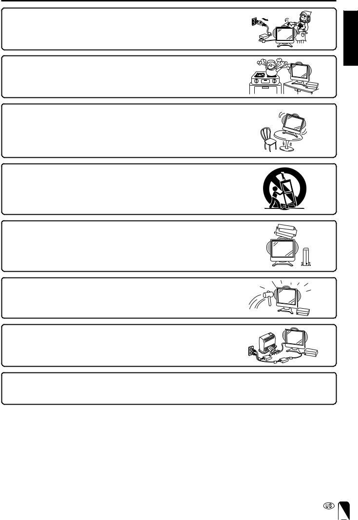
■ Cleaning—Unplug the power cord from the AC outlet before cleaning the prod- |
|
uct. Use a damp cloth to clean the product. Do not use liquid cleaners or aerosol |
ENGLISH |
cleaners. |
|
|
|
■ Water and moisture—Do not use the product near water, such as bathtub, |
|
washbasin, kitchen sink and laundry tub, swimming pool and in a wet basement. |
|
■ Stand—Do not place the product on an unstable cart, stand, tripod or table. |
|
Placing the product on an unstable base can cause the product to fall, resulting |
|
in serious personal injuries as well as damage to the product. Use only a cart, |
|
stand, tripod, bracket or table recommended by the manufacturer or sold with the |
|
product. When mounting the product on a wall, be sure to follow the manufactur- |
|
er’s instructions. Use only the mounting hardware recommended by the manu- |
|
facturer. |
|
■ When relocating the product placed on a cart, it must be moved with utmost |
|
care. Sudden stops, excessive force and uneven floor surface can cause the |
|
product to fall from the cart. |
|
■ Ventilation—The vents and other openings in the cabinet are designed for |
|
ventilation. Do not cover or block these vents and openings since insufficient |
|
ventilation can cause overheating and/or shorten the life of the product. Do not |
|
place the product on a bed, sofa, rug or other similar surface, since they can |
|
block ventilation openings. This product is not designed for built-in installation; do |
|
not place the product in an enclosed place such as a bookcase or rack, unless |
|
proper ventilation is provided or the manufacturer’s instructions are followed. |
|
■ The Liquid Crystal panel used in this product is made of glass. Therefore, it can |
|
break when the product is dropped or applied with impact. Be careful not to be |
|
injured by broken glass pieces in case the Liquid Crystal panel breaks. |
|
■ Heat sources—Keep the product away from heat sources such as radiators, |
|
heaters, stoves and other heat-generating products (including amplifiers). |
|
■ The Liquid Crystal panel is a very high technology product with 921,600 thin film transistors, giving you fine picture |
|
details. |
|
Occasionally, a few non-active pixels may appear on the screen as a fixed point of blue, green or red. |
|
Please note that this does not affect the performance of your product. |
|
5

IMPORTANT SAFETY PRECAUTIONS (Continued)
■If an outside antenna is connected to the television equipment, be sure the antenna system is grounded so as to provide some protection against voltage surges and built-up static charges. Section 810 of the National Electrical Code provides information with respect to proper grounding of the mast and supporting structure, grounding of the lead-in wire to an antenna discharge unit, size of grounding conductors, location of antenna-discharge unit, connection to grounding electrodes, and requirements for the grounding electrode.
EXAMPLE OF ANTENNA GROUNDING AS PER
NATIONAL ELECTRICAL CODE
|
ANTENNA |
|
LEAD IN |
|
WIRE |
GROUND |
|
CLAMP |
|
|
ANTENNA |
ELECTRIC |
DISCHARGE UNIT |
(NEC SECTION 810-20) |
|
SERVICE |
|
EQUIPMENT |
GROUNDING CONDUCTORS |
|
|
|
(NEC SECTION 810-21) |
|
GROUND CLAMPS |
|
POWER SERVICE GROUNDING |
|
ELECTRODE SYSTEM |
NEC—NATIONAL ELECTRICAL CODE |
(NEC ART 250, PART H) |
■ Lighting – For added protection for this television equipment during a lightning storm, or when it is left unattended and unused for long period of time, unplug it from the wall outlet and disconnect the antenna. This will prevent damage to the equipment due to lightning and power-line surges.
■ Power Lines – An outside antenna system should not be located in the vicinity of overhead power lines or other electric light or power circuits, or where it can fall into such power lines or circuits. When installing an outside antenna system, extreme care should be taken to keep from touching such power lines or circuits as contact with them might be fatal.
■ To prevent fire, never place any type of candle or naked flames on the top or near the TV set.
■ To prevent fire or shock hazard, do not expose this products to dripping or splashing. No objects filled with liquids, such as vases, should be placed on the products.
6
REGARDING BATTERY CARE |
|
|
|
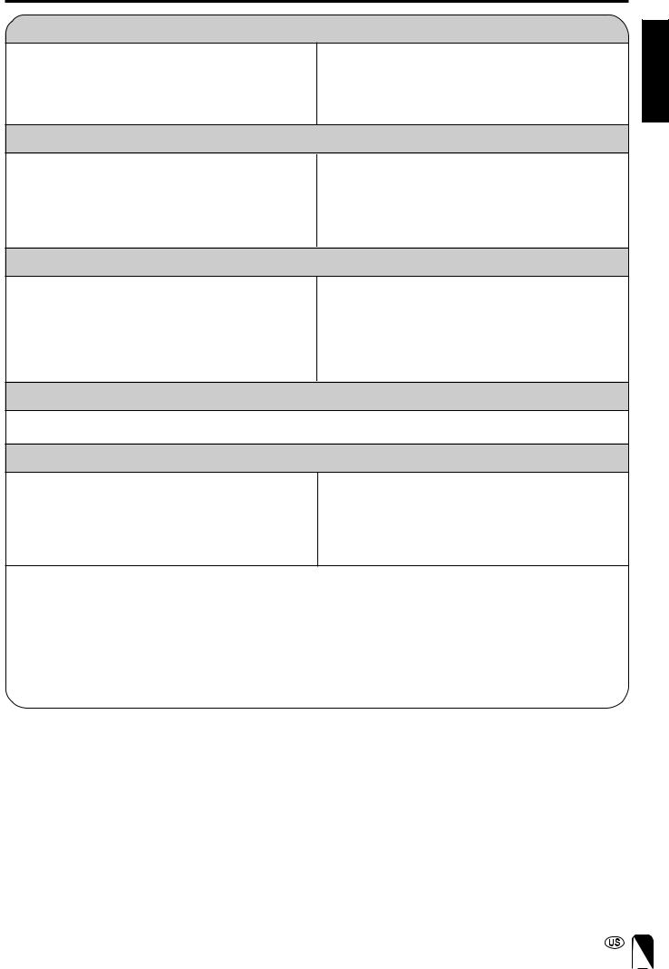
Charge the battery before use. |
ENGLISH |
||
• The battery used in the product is a lithium-ion battery. Even if |
• Make sure to charge the battery until the charge indicator of |
||
|
|||
the battery is charged and stored, the amount of charge in the |
the product goes off (fully charged). The operating time is |
|
|
battery will drop. |
shortened when using a battery which has not been fully |
|
|
|
charged. (For a detailed description of how to charge the |
|
|
|
battery, refer to page 20.) |
|
|
Precautions to be Taken during Charging
•Charge the battery only at temperatures within the range of 50°F to 86°F (10°C to 30°C) (temperatures that are comfortable for people). At lower temperatures it becomes more difficult to charge the battery and the battery deteriorates. It is not possible to sufficiently charge the battery at high temperatures.
•The battery may become hot during charging or during use, but this is not a sign of malfunctioning.
•It may take more time to fully charge a hot battery.
Regarding Operating Time and Use under Low Temperatures for the Battery
•The battery has a certain life expectancy. The battery is consumed as time elapses even if the battery is not used. A battery that has been used for about a year may give you less operating time depending on the conditions under which it was stored. If a battery that has been charged correctly operates for a much shorter time than usual, it has reached the end of its life and must be replaced with a new battery.
•When the battery is at a low temperature (lower than 50°F (10°C)) in winter, the operating time may be very short. The battery undergoes an internal chemical reaction in order to generate electricity. When the temperature outside is lower, the chemical reaction becomes less vigorous and operating time becomes shorter.
How to Get the Most out of the Battery
• Turn off the power supply frequently when not in use in order to give the battery longer life.
Storage Precautions
•The battery is consumed as time elapses even if the battery is not used. To prevent consumption;
(1)If the battery will not be used for a long time, use the product to run down what is left of the battery charge and set “Battery charge” to “off” in the menu screen. (Refer to page 28.)
(2)Make sure to use the battery at least once every six months.
|
|
Battery Specification |
|
|
|
|
|
|
|
|
|
|
Battery type |
lithium-ion battery |
|
|
Nominal voltage |
11.1 V |
|
|
Battery capacity |
5700 mAh |
|
|
Operating temperature |
50°F to 86°F (10°C to 30°C) |
|
|
Maximum dimensions |
appx. Length 8 23/64 inch (212 mm) × Width 1 5/8 inch (41 mm) × Height 1 35/64 inch (39 mm) |
|
|
Weight |
appx. 1.1 lbs. (0.5 kg) |
|
7
REGARDING BATTERY CARE (Continued)
Prohibited use for which safety is not guaranteed.
•Do not try to disassemble or modify the battery. The battery contains safety mechanisms and protection devices. Damaging these safety devices may cause the battery to generate heat or smoke, or to rupture or ignite.
•Do not connect the + and – terminals together with metal such as wires. Do not carry or store the battery together with metal objects such as necklaces and hairpins. Doing so may cause the battery to be short-circuited so as to cause an extremely large amount of electric current to flow, which may cause the battery to generate heat or smoke, rupture or ignite, or may cause metal objects such as wire, necklaces, or hairpins to heat up.
•Do not expose batteries to fire or heat. Doing so may cause insulating materials to melt, damage gas exhaust valves or safety mechanisms, or ignite electrolytic solutions, which may cause the battery to generate heat or smoke, rupture or ignite.
•Do not leave the battery in or near fire, stoves, or other high-temperature locations (of temperatures greater than 140°F (60°C)). If a resin separator is damaged by heat, the battery may become internally short-circuited and this may cause the battery to generate heat or smoke, rupture or ignite.
•Do not expose the battery to water or salt water, or allow the battery to get wet. If the protection device contained in the battery is broken, this may cause the battery to generate heat or smoke, rupture or ignite.
•Do not charge the battery near a fire or in direct sunlight. If the battery becomes hot, the protection device for preventing danger operates to disable the battery from being charged. If the protection device contained in the battery becomes broken, the battery is charged at an abnormal electric current or voltage. An abnormal chemical reaction occurs inside the battery which may cause the battery to generate heat or smoke, rupture or ignite.
•Charge the battery in compliance with the specified charging conditions. If the battery is charged without compliance to the charging conditions (at temperatures greater than the specified temperature, at voltages and electric current greater than the specified amount or with modified chargers), the battery may be overcharged or charged at an abnormal electric current and an abnormal chemical reaction may occur inside the battery, which may cause the battery to generate heat or smoke, rupture or ignite.
•Do not pierce the battery with nails, strike the battery with a hammer, or step on the battery. Doing so may cause the battery to generate heat or smoke, rupture or ignite.
•Do not subject the battery to strong impacts or throw it away. If the protection device contained in the battery becomes broken, the battery is charged at an abnormal electric current or voltage. An abnormal chemical reaction may then occur inside the battery, which may cause the battery to generate heat or smoke, rupture or ignite.
•Do not use the battery if it has been considerably damaged or deformed. This may cause the battery to generate heat or smoke, rupture or ignite.
•Do not solder directly onto the battery. Doing so may cause insulating materials to melt, or damage gas exhaust valves or the safety mechanism, which may cause the battery to generate heat or smoke, rupture or ignite.
•Use a battery case when carrying the battery.
•Keep the battery out of reach of children.
•In the event that the fluid inside the battery gets into one’s eye, do not rub the eye because this may cause loss of eyesight. Rinse the eye with clean water and consult a doctor immediately. In the event that the fluid becomes attached to skin or clothes, wash it off with clean water immediately as this may cause injury.
8

CORRECT USE OF THE PRODUCT |
|
|
Precautions Regarding Radio Waves |
ENGLISH |
|
■ Do not use the product at the following locations. There may be cases where noise occurs or transmission/reception is |
||
|
||
not possible. |
|
|
• Locations where magnetic fields, electrostatic or interference occurs due to devices such as Bluetooth, wireless LANs, or |
|
|
microwave ovens etc. that utilize the same frequency band (2.4 GHz) as the product. (There may be cases where radio waves |
|
|
cannot reach depending on the environment.) |
|
|
• Keep the product away from a radio devices during use. (There may be cases of noise interference.) |
|
■Under the same frequency band as the product uses, in addition to Bluetooth, wireless LANs, and microwave ovens etc. that utilize the same frequency band (2.4 GHz) as the product, operation can also take place at on-site radio stations that require a license for mobile object identification used in factories and manufacturing lines etc. and
specified low power radio stations.
•Before using the product, make sure that there is no on-site radio stations for mobile object identification or specified low power radio stations operating in the vicinity of the product.
•If there is any interference occurring to on-site radio stations for mobile object identification due to the product, stop using the product immediately.
Regarding Range of Usage
■ The product is limited to domestic use.
(There is a possibility that transmission distance may become short depending on the communication environment.)
■In the following cases, reception may become bad or impossible, which may cause sound and pictures to be interrupted (pictures and sound are stopped), or blocks of noise to appear.
•Using the product in a reinforced concrete building such as a condominium building or a house of a metal structure.
•Using the product at locations near large-scale metallic furniture.
•Using the product in a crowd of people or close to buildings or obstacles, etc.
•Using the product at locations where magnetic fields, electrostatic and interference occur due to devices such as Bluetooth, wireless LANs, or microwave ovens, etc. that utilize the same frequency band (2.4 GHz) as the product.
■ Regarding reflected radio waves
•Radio waves that reach a television receiver are radio waves (direct waves) directly transmitted from a transmitter and radio waves (reflected waves) arriving from various directions as a result of being reflected by walls, furniture, or buildings etc. There are good and bad positions in terms of wave conditions due to the influence of these reflected waves, which may cause poor picture reception. In this case, try changing the location of the TV receiver slightly. There are cases where pictures and sound are distorted or interrupted due to the reflected waves as a result of a person passing over or approaching between the transmitter and the television receiver.
When a signal other than a regular signal is input
•When a signal other than a regular signal that is incompatible with this unit is input, the screen may freeze, but this is not a malfunction.
•When a signal other than a regular signal is input from the Antenna, AV-IN1, AV-IN2, or AV-IN3 terminals, reception may be bad depending on the performance of the Wireless Center, and the message “THIS SIGNAL IS NOT COMPATIBLE” will display.
•Signals compatible with the Wireless Center are as follows:
H:15.625 kHz / V: 50.0 Hz, 59.52 Hz
H: 15.73426 kHz / V: 59.94 Hz
(Note: Reception may be available with AV-IN4.)
Precaution Regarding Electromagnetic Wave Disturbance
•If electric devices, such as a cellular phone, are used near this unit, electromagnetic wave disturbance may occur between apparatus. In such cases, the picture quality may decrease and noise may appear.
9

SUPPLIED ACCESSORIES
Confirm that the following accessories are provided with the product.
Wireless remote control (×1), Remote control holder (×1), |
|
|
Battery (×1) |
|
|
“AAA” size (UM/SUM-4) dry batteries (×2) |
|
|
|
||
|
|
|
|
||
RRMCGA152WJSA |
|
|
|
|
|
|
|
UBAT1A011WJZZ |
|
|
|
|
|
|
|
Terminal cover |
|
|
LHLDZA216WJZZ |
|
|
|
|
(See pages 11, 15, 18) |
|
(See page 19) |
|
|
|
AC adapters (×2) |
Wireless Center (×1), Wireless Center stand (×1) |
|
|||
|
UADP-A041WJPZ |
|
|
|
|
|
|
MAIN |
POWER SIGNAL LEVEL |
|
|
|
|
POWER |
|
|
|
|
|
Screws (×3) |
|
|
|
UADP-A042WJPZ |
|
|
|
GDAI-A074WJSA |
|
|
|
(See page 17) |
|
|
|
QACCDA023WJPA × 2 pcs |
Video controller (×1) |
Manuals |
|
||
|
|
|
|
||
|
|
|
|
TINS-B124WJZZ |
|
|
|
|
|
|
ENGLISH |
*Product shape varies in some countries. |
|
|
LC-15L1U |
ÇAIS |
|
|
|
|
|||
(See pages 13, 21) |
|
|
|
|
FRAN |
|
|
|
|
|
|
|
|
|
|
LIQUID CRYSTAL TELEVISION |
ESPAÑOL |
Cable clamps (×2), Table stand (×1) |
|
|
TÉLÉVISEUR ACL |
|
|
|
|
TELEVISOR CON PANTALLA |
ÊS |
||
|
|
DE CRISTAL LÍQUIDO |
|||
QCNWGA033WJPZ |
TELEVISOR DE CRISTAL |
PORTUGU |
|||
|
|
LÍQUIDO |
|||
|
|
OPERATION MANUAL |
|||
|
|
(See pages 55, 57, 60) |
|
||
|
|
MODE D’EMPLOI |
|
||
LHLDW0109CESA |
|
MANUAL DE OPERACIÓN |
|
||
|
MANUAL DE OPERAÇÃO |
|
|||
|
|
|
|
|
|
|
|
Antenna cables (×2) |
|
|
|
(See page 59) |
|
|
|
|
|
|
|
QCNWG0003CEPA |
Connecting System Chart of |
|
|
|
|
LC-15L1U |
|
||
|
|
|
|
|
|
|
|
|
|
TCAUZA072WJZZ |
|
|
|
|
|
Registration Card |
|
|
|
QCNWG0004CEZZ |
TCAUDEA028WJZZ |
||
|
|
|
|
Caution Sheet |
|
(See page 15) |
CDAI-A072WJ02 |
(See page 12) |
|
TCAUZA071WJZZ |
|
|
|
|
|||
10
PREPARATION
Using the Remote Control
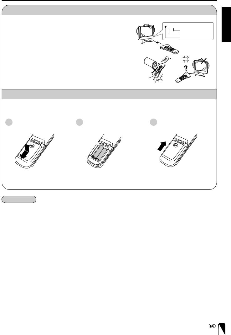
■Use the remote control by pointing it toward the remote control sensor window on the main unit. Objects between the remote control and sensor window may prevent proper operation.
Cautions regarding use of the remote control
■Do not expose the remote control to shock.
In addition, do not expose the remote control to liquid, and do not place it in an area with high humidity.
■Do not install or place the remote control under direct sunlight. The heat may cause deformation of the unit.
■The remote control may not work properly if the remote control sensor window of the main unit is under direct sunlight or strong lighting. In such cases, change the angle of the lighting or LCD TV set, or operate the remote control closer to the remote control sensor window.
POWER CHARGE SLEEP

 SLEEP indicator CHARGE indicator POWER indicator Remote sensor window
ENGLISH |
Batteries for the Remote Control
Before using the LCD TV set for the first time, install two (“AAA” size, UM/SUM-4) batteries (supplied). When the batteries become depleted and the remote control fails to operate, replace the batteries with new (“AAA” size, UM/SUM-4) batteries.
1 Open the battery cover. |
2 Insert two (“AAA” size, UM/SUM- |
3 Close the battery cover. |
|
4) batteries. |
|
|
– |
|
|
+ |
|
|
+ |
|
|
– |
|
■ Slide the cover while pressing the |
■ Position the positive and negative |
(b) part. |
ends of the batteries as indicated in |
|
the compartment. |
■Engage the claw on the cover into the battery housing and slide shut.
 Caution!
Cautions regarding batteries
Improper use of batteries can result in chemical leakage and/or explosion. Be sure to follow the instructions below.
•Place batteries with their terminals corresponding to the (+) and (–) as indicated in the compartment.
•Different types of batteries have different characteristics. Do not mix batteries of different types.
•Do not mix old and new batteries. Mixing old and new batteries can shorten the life of new battery and/or cause the old battery to leak chemicals.
•Remove batteries when they become weak.
Chemicals that leak from batteries can cause a rash. If chemical leakage is found, wipe with a cloth.
•The batteries supplied with the product may have a shorter life expectancy due to storage conditions.
•If the remote control will not be used for an extended period of time, remove the batteries from the remote control.
11
PREPARATION (Continued)
Antenna Connection
ANTENNAS
•The antenna requirements for good color television reception are more important than those for black & white television reception. For this reason, a good quality outdoor antenna is strongly recommended.
The following is a brief explanation of the type of connections that are provided with the various antenna systems.
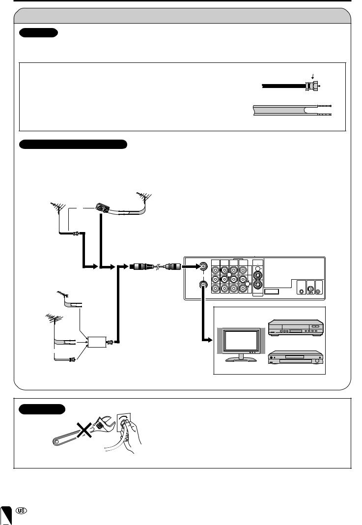
F-type connector
1.A 75-ohm system is generally a round cable with F-type connector that can easily be attached to a terminal without tools (not supplied).
2.A 300-ohm system is a flat “twin-lead” cable that can be attached to a 75-ohm terminal through a 300-75-ohm adapter (not supplied).
75-ohm coaxial cable (round)
300-ohm twin-lead cable (flat)
OUTDOOR ANTENNA CONNECTION
•Use one of the following two diagrams if you connect an outdoor antenna.
A:Using a VHF/UHF combination outdoor antenna
B:Using separate VHF and/or UHF outdoor antennas
•Connect the outdoor antenna cable lead-in to ANT. (Antenna terminal) on the rear of the Wireless Center.
A: Combination VHF/UHF antenna
VHF/UHF |
300/75-ohm |
VHF/UHF |
|
adapter |
|||
antenna |
|||
antenna |
(not supplied) |
||
|
|||
|
or |
|
|
300-ohm |
|
|
twin-lead |
|
75-ohm |
|
|
coaxial cable |
|
|
|
|
IN |
B: Separate VHF and/or UHF antennas |
Antenna cable |
ANT. |
UHF |
|
antenna |
OUT |
|
|
300-ohm |
|
twin-lead |
|
VHF |
|
antenna |
|
300-ohm |
|
twin-lead |
IN OUT |
|
|
or |
Combiner |
|
(not supplied) |
75-ohm |
|
coaxial cable |
|
Wireless Center
AV-IN3 |
AV-IN2 |
AV-IN1 |
MONITOR |
AV-IN1 |
|
|
/OUT |
OUT |
|
|
|||
|
|
|
|
|
||
|
|
|
VIDEO |
|
|
|
|
|
|
AUDIO |
|
|
|
|
|
|
L |
IR |
POWER |
FACTORY |
|
|
|
|
OUT |
INPUT |
SERVICE |
|
|
|
|
|
DC12V |
|
|
|
|
AUDIO |
|
|
|
|
|
|
R |
MONITOR |
|
|
|
|
|
|
OUT |
|
|
|
|
|
|
S-VIDEO |
|
|
|
|
|
|
VCR |
|
|
|
|
|
TV |
|
|
|
|
|
|
|
DVD |
|
|
TV/VCR/DVD, etc.
NOTICE
F-type connector |
F-type connector should be finger-tightened only. |
When conecting the RF cable to the TV set, do not tighten F-type connector with tools.
If tools are used, it may cause damage to your TV set. (The breaking of internal circuit, etc.)
75-ohm coaxial cable
12

PREPARATION (Continued) |
|
|
Antenna Connection (Continued) |
ENGLISH |
|
CABLE TV (CATV) CONNECTION |
||
|
||
• A 75-ohm coaxial cable connector is built into the set for easy hookup. When connecting the 75-ohm coaxial cable to the |
|
|
set, screw the 75-ohm cable to the ANT. terminal. |
|
|
• Some cable TV companies offer “premium pay channels”. Since the signals of these premium pay channels are scram- |
|
|
bled, a cable TV converter/descrambler is generally provided to the subscriber by the cable TV company. This converter/ |
|
|
descrambler is necessary for normal viewing of the scrambled channels. (Set your TV to channel 3 or 4, typically one of |
|
|
these channels is used. If this is unknown, consult your cable TV company.) For more specific instructions on installing |
|
|
cable TV, consult your cable TV company. One possible method of utilizing the converter/descrambler provided by your |
|
|
cable TV company is explained below. |
|
|
Please note: An RF switch provided with two inputs (A and B) is required (not supplied). |
|
“A” position on the RF switch (not supplied): “B” position on the RF switch (not supplied):
You can view all unscrambled channels by using the TV’s channel keys.
You can view the scrambled channels via the converter/descrambler by using the converter’s channel keys.
RF switch (not supplied)
Two-set 


 signal
splitter 


 Cable TV line
(not
supplied)
OUT |
IN |
Cable TV converter/ descrambler
(not supplied)
Note:
• Consult your SHARP Dealer or Service Center for the type of splitter, RF switch or combiner that might be required.
Power Connection
Connect to the DC input terminal of each product.
AC cord
AC wall outlet
IR |
POWER |
FACTORY |
OUT |
INPUT |
SETTING |
|
DC12V |
|
AC adapter
TV main unit |
AC adapter |
AC cord |
|
Wireless
Center
Note:
AC wall outlet
•Always turn the MAIN POWER button of the LCD TV set and the power button of the Wireless Center to OFF when connecting the AC adapters.
•If there is a Sharp product close to the video controller, the product may malfunction during transmission of the video controller.
•Unplug the AC adapters from the LCD TV set, Wireless Center unit and AC wall outlet when the LCD TV set is not to be used for a long period of time.
13

MAIN UNIT PART NAMES
Numbers in indicate the main pages where the corresponding item is described in this manual.
Main unit (Top view: Control section)
VOL (–)/(+) 33 |
|
|
|
|
|
|
|
|
MAIN POWER 31 |
||||
|
|
CH ( |
)/( ) 34 |
|
|
TV/VIDEO 32 |
|
||||||
|
|
- VOL + |
|
|
|
MENU 35 |
|
|
|
|
|||
|
|
|
|
|
|
||||||||
|
|
|
|
CH |
|
MENU TV/VIDEO |
|
MAIN POWER |
|
||||
|
|
|
|
|
|
|
|
|
|
|
|
|
|
Main unit (Front view)
Left speaker |
Right speaker |
|
|
SLEEP indicator |
36 |
|
CHARGE indicator 20 |
|
|
POWER indicator |
22 |
Table stand (Detachable) 15 |
Remote sensor window 11 |
|
14
MAIN UNIT PART NAMES (Continued)
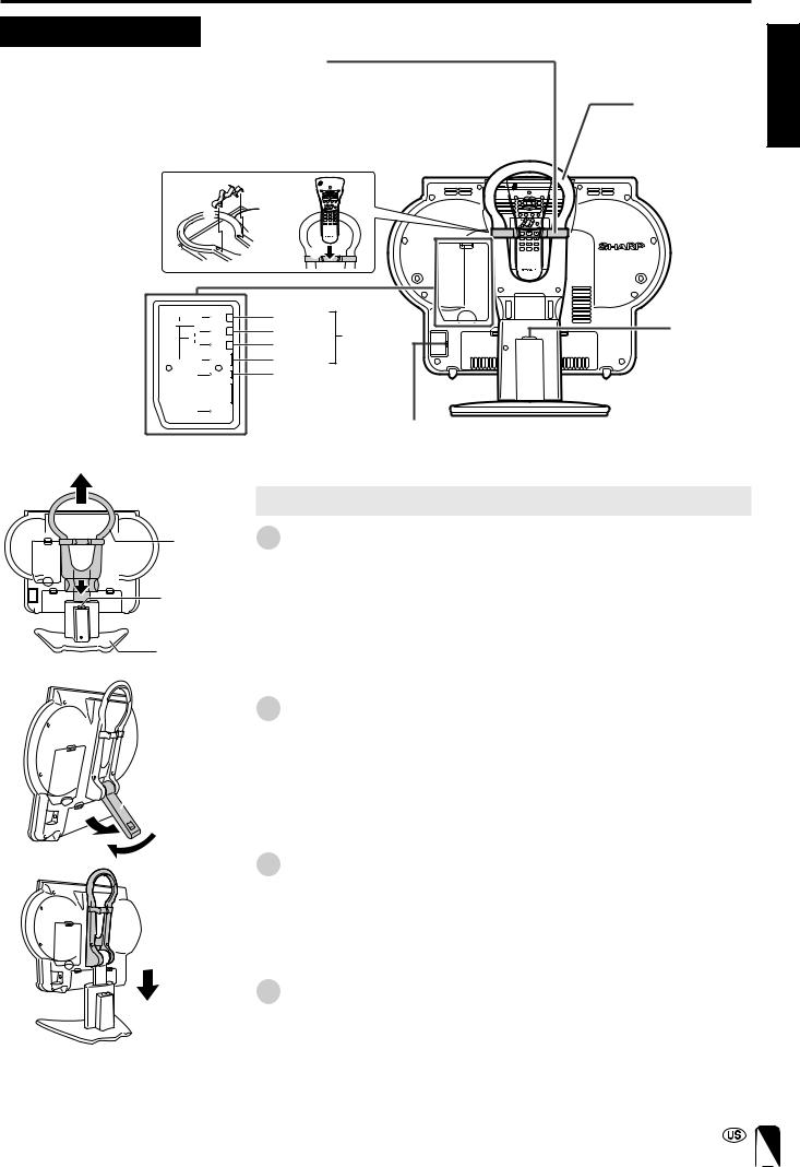
Main unit (Rear view)
Remote control holder
The remote control can be placed in the remote control holder when moving the TV.
1Attach the remote control holder to the handle with the arrow ( ) in the center of
the holder facing upward.
2Place the remote control in the remote control holder.
1
|
2 |
|
VIDEO |
VIDEO |
|
AV-IN4 |
AUDIO(L) |
|
L |
AV-IN4 |
|
AUDIO |
AUDIO(R) |
|
R |
|
|
S-VIDEO |
S-VIDEO |
|
PHONE |
HEADPHONE jack |
|
HEAD |
|
|
FACTORY
SERVICE
POWER
DISPLAY
SLEEP |
PIC. FLIP |
ENTER
MUTE BRIGHT TV/VIDEO MENU
FLASH
BACK
VOL CH
MTS
POWER INPUT DC 15 V
Handle |
ENGLISH |
|
Table stand release button
|
Removing and Attaching the Table Stand |
Handle |
1 Lift the main unit straight up by holding the handle while depressing the table |
|
stand release button. |
Table stand |
|
release button |
|
Table stand |
|
2 Unfold the stand.
• Securely unfold the stand until you hear a clicking sound. Only use the stand after first unfolding until a clicking sound is heard to ensure that it is stable.
 Stand
Stand
3 Fold up the stand.
• Return the stand to its original unfolded position.
4 Insert the main unit straight into the table stand.
•The main unit cannot be inserted if inclined on an angle. Inserting the main unit with force can cause damage or a malfunction.
15
MAIN UNIT PART NAMES (Continued)
Removing the Back Cover
■ Before connecting cables and cords to the rear terminals, remove the back covers. Push in the tabs and pull out the back covers carefully.
■ To mount the cover, insert the 2 hooks on the bottom of the cover into the cabinet and press on the upper part of the back cover until the tab locks in place with a click.
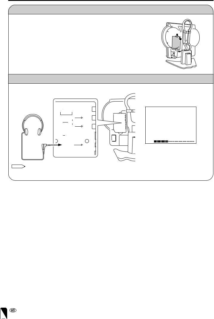
Listening with Headphones
■ Plug the headphone mini-plug into the HEADPHONE jack located on the rear of the TV set.
▼ On-screen display
VIDEO 

Headphones
AV-IN4
L
AUDIO
R
S-VIDEO 

VOLUME
20
HEAD
PHONE Adjust the sound volume using VOL (e)/(f) on the  remote control.
Rear terminal
Note:
•Headphones are not included in the supplied accessories.
•No sound is heard from the main unit speakers when a headphone mini-plug is connected into the HEADPHONE jack.
16

WIRELESS CENTER PART NAMES
TV main unit
Wireless Center
Transmission
POWER Indicator |
|
|
When the TV is turned off with the remote control, the |
ENGLISH |
|
Wireless Center is switched to standby (POWER indicator |
||
|
||
is lit red). (There may be a time lag of about 5 to 6 |
|
|
seconds.) |
|
|
Placing the Wireless Center Where You Want It |
|
|
We recommend placing the Wireless Center in an area |
|
|
where there are no obstructions to impede radio wave |
|
|
transmission/reception. |
|
|
(Do not place the Wireless Center in a box.) |
|
Front
MAIN POWER SIGNAL LEVEL
POWER
MAIN |
POWER indicator |
SIGNAL LEVEL |
POWER · Green: |
indicator |
|
button |
Operation in |
(Reception gain) |
|
progress |
· Green: |
|
(when power is on) |
Communication |
|
· Red: Standby |
in progress |
|
|
· Red: |
|
|
Difficulty |
|
|
in transmission |
· Not lit:
Not communicating
Note:
•The distance for which transmission is possible between the main unit and Wireless Center is about 15 metres. However, this distance may vary depending on the location or conditions under which the Wireless Center is used.
•If the main unit gets close to the Wireless Center, there may be cases where noise appears on the screen. In this case, keep the main unit away from the Wireless Center until the noise decreases, or try to change the transmission channel setting (page 28).
|
|
|
|
|
|
Rear |
|
|
|
Antenna |
|
|
|
|
|
VIDEO |
|
|
|
|
AV-IN1 |
|
AUDIO (L) |
AV-IN1 (S-VIDEO) |
|||||
input |
|
|
|
|
|
AUDIO (R) |
|
|
|
terminal |
|
|
|
|
|
|
|
||
|
|
|
|
|
|
|
|
|
|
IN |
AV-IN3 |
AV-IN2 |
AV-IN1 |
MONITOR |
AV-IN1 |
|
|
|
|
|
|
|
|
||||||
|
/OUT |
OUT |
|
|
|
||||
|
|
|
|
|
|
|
|||
|
|
|
|
|
|
VIDEO |
|
|
|
ANT. |
|
|
|
|
|
|
|
|
|
|
|
|
|
|
|
AUDIO |
|
|
|
|
|
|
|
|
|
L |
|
IR |
POWER FACTORY |
|
|
|
|
|
|
|
|
OUT |
INPUT SERVICE |
|
|
|
|
|
|
|
|
|
DC12V |
|
|
|
|
|
|
AUDIO |
|
|
|
OUT |
|
|
|
|
|
R MONITOR |
|
|
|
|
|
|
|
|
|
OUT |
|
|
|
|
|
|
|
|
|
S-VIDEO |
|
|
|
Antenna |
|
|
|
|
|
MONITOR OUT |
Factory |
||
|
|
|
|
|
(S-VIDEO) |
|
|||
output |
|
|
|
|
|
|
adjustment |
||
|
|
|
|
|
|
|
|
||
terminal |
|
|
|
MONITOR |
VIDEO |
terminal |
|||
|
|
|
|
AUDIO (L) |
POWER INPUT |
||||
|
|
|
|
OUT |
AUDIO (R) |
||||
|
|
|
|
|
|
|
DC 12V |
||
|
|
|
|
|
|
|
|
|
|
|
|
AV-IN2 |
VIDEO |
|
Video control |
||||
|
|
AUDIO (L) |
|||||||
|
|
/OUT |
|
AUDIO (R) |
terminal |
||||
|
|
|
|
|
|
|
|||
|
VIDEO |
|
|
|
|
|
|
||
AV-IN3 |
AUDIO (L) |
|
|
|
|
|
|||
|
AUDIO (R) |
|
|
|
|
|
|||
Setting up the Wireless Center
• The Wireless Center can be placed horizontally or upright. |
|
• When placing horizontally: |
• When placing upright: |
The side on which the rubber feet are attached is the |
Fasten the stand to the bottom of the Wireless Center with |
bottom. |
the screws provided. |
|
Wireless Center |
|
stand |
Rubber foot |
Rubber foot |
* Failure to securely fasten the stand may cause the Wireless Center to tip over during use.
17

REMOTE CONTROL
1
2
3
4
5
6
7
8
9
POWER
|
DISPLAY |
SLEEP |
PIC. FLIP |
|
ENTER |
MUTE |
BRIGHT TV/VIDEO MENU |
|
FLASH- |
|
BACK |
VOL |
CH |
10
 11
11
12
13
14
15
1 POWER (p. 22)
Switch the Liquid Crystal Television power on or off.
2 DISPLAY
Display the channel and time information.
3 SLEEP (p. 36)
Set the sleep timer.
4 ENTER
Execute a command.
5 BRIGHT (p. 37)
Adjust the brightness of the screen.
6 MUTE (p. 33)
Mute the sound.
7 VOL (+)/(–) (p. 33)
Set the volume.
8 CH ( )/( ) (p. 34)
Select channel.
9 MTS (p. 33)
Select audio settings.
10 PIC. FLIP (p. 38)
Set the orientation of the picture.
11 a/b/c/d(Cursor control) (p. 22)
Select a desired item on the screen.
12 TV/VIDEO (p. 32)
Select a Liquid Crystal Television input source.
13 MENU (p. 35)
Display the menu screen.
14 FLASHBACK (p. 34)
Return to the previous channel.
15 Channel Select (p. 34)
Set the channel.
18
POWER
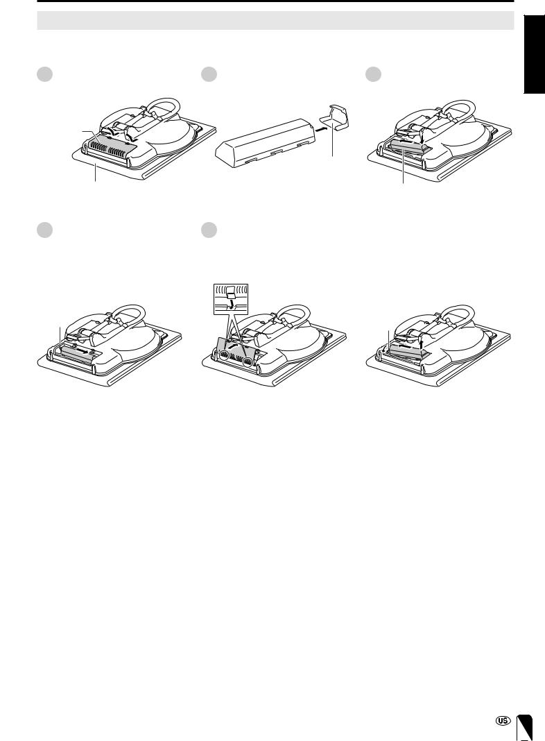
Turning the Main Power on and off
See page 15 for how to remove the table stand.
■ Installing the Battery
1 Open the cover of the battery |
2 Remove the terminal cover of the |
case. |
battery. |
3 |
Pack toward the left side first and |
ENGLISH |
|
||
|
then push the battery inside the |
|
|
compartment. |
|
Cover of the battery case
Terminal cover
Place on a soft cloth. |
Battery |
4 Shift the battery to the right.
•The lever will return to its original position.
•Move the battery to the right until the lever returns completely.
5 Close the cover of the battery case.
•Align the tabs of the cover with the corresponding grooves in the TV and snap into position.
■ When Removing
With the lever pulled forward, lift up on the battery while pushing to the left.
•Always make sure to attach the terminal cover to the removed battery.
Lever |
Lever |
19
POWER (Continued)
■ Charging the Battery
Charge the battery when using for the first time (“BATTERY CHARGE” is set to “ON” (page 28)). Plug the AC adapter into a wall outlet and the corresponding connector on the TV. The CHARGE indicator lights and charging begins. When charging is completed, the CHARGE indicator turns off.
AC wall outlet
CHARGE |
AC adapter |
AC cord |
TV main unit indicator |
|
Charging while Viewing:
The battery will be charged, while you are viewing if “BATTERY CHARGE” is set to “ON” (page 28). In this case, charging takes about 12 hours. To preserve battery performance it is recommended that “BATTERY CHARGE” be set to “OFF” if battery power is not in constant use.
Note:
•Charging time may be longer depending on ambient temperature, battery condition and other factors. Check to make sure the CHARGE indicator is not lit before using.
General Reference for Battery Viewing Time
The viewing time differs according to the BRIGHTNESS setting (page 37).
Note:
•Operating time may be shorter depending on certain conditions such as use in cold climates.
When You Want to Check the Amount of Remaining Battery Power
Press the DISPLAY button on the remote control.
•Although the remaining battery power indicator will flash red for the first 10 seconds, it will remain lit constantly after that time.
•The amount of remaining charge is only displayed when operating on battery power.
•The remaining battery power indicator changes according to battery status, temperature and conditions of use. This indicator should be used as a reference for the amount of battery power remaining.
BRIGHTNESS Setting |
Viewing Time |
BRIGHT |
about 1.5 hours |
|
|
NORMAL |
about 2 hours |
|
|
DARK |
about 3 hours |
|
|
Remaining  battery
power indicator
The remaining battery power indicator changes as shown below when the battery level becomes low.
(Green) (Green) (Red)
The remaining battery power indicator is displayed constantly regardless of whether the on-screen display is on or off when the battery level is low.
When Battery is not Charging Properly
•If the CHARGE indicator begins to flash extremely rapidly during charging, this means that charging is not proceeding normally.
•When the CHARGE indicator flashes at an interval of about a second during charging, the TV main unit is not in an appropriate temperature range for charging. The temperature range for charging should be approximately between 50°F (10°C) and 86°F (30°C).
•If the CHARGE indicator begins to flash extremely rapidly (at about 3 flashes a second) during charging, this means that charging is not proceeding normally because the battery may malfunction. Replace the battery with the new one.
20
 Loading...