

Schneider Electric KVA 480 V, KVA 400 V User Manual
Galaxy VM
160–225 kVA 480 V,
160–200 kVA 400 V
Operation
09/2018
www.schneider-electric.com

Legal Information
The Schneider Electric brand and any registered trademarks of Schneider Electric
Industries SAS referred to in this guide are the sole property of Schneider Electric
SA and its subsidiaries. They may not be used for any purpose without the owner's
permission, given in writing. This guide and its content are protected, within the
meaning of the French intellectual property code (Code de la propriété
intellectuelle français, referred to hereafter as "the Code"), under the laws of
copyright covering texts, drawings and models, as well as by trademark law. You
agree not to reproduce, other than for your own personal, noncommercial use as
defined in the Code, all or part of this guide on any medium whatsoever without
Schneider Electric's permission, given in writing. You also agree not to establish
any hypertext links to this guide or its content. Schneider Electric does not grant
any right or license for the personal and noncommercial use of the guide or its
content, except for a non-exclusive license to consult it on an "as is" basis, at your
own risk. All other rights are reserved.
Electrical equipment should be installed, operated, serviced, and maintained only
by qualified personnel. No responsibility is assumed by Schneider Electric for any
consequences arising out of the use of this material.
As standards, specifications, and designs change from time to time, please ask for
confirmation of the information given in this publication.

Table of Contents
Important Safety Instructions — SAVE THESE
160–225 kVA 480 V, 160–200 kVA 400 V
INSTRUCTIONS
Safety Precautions .....................................................................................6
.........................................................................................5
Overview of UPS User Interface...............................................................7
Overview of Mimic Diagram.........................................................................8
Overview of Status LEDs.............................................................................8
Display Menu Tree......................................................................................8
Display Symbols....................................................................................... 10
Overview of Controller Interface................................................................. 10
Configuration ............................................................................................. 11
Add a New User or Edit an Existing User .................................................... 11
Delete a User ........................................................................................... 11
Configure the Display Preferences............................................................. 12
Configure the Display Settings................................................................... 12
Configure the UPS Output Voltage Compensation....................................... 13
Configure High Efficiency Mode................................................................. 14
Enable Peak Shaving Mode ...................................................................... 15
Configure the Redundancy Level of the Parallel System ..............................16
Configure the Input Contacts ..................................................................... 16
Configure the Output Relays ..................................................................... 17
Configure Reminder Settings..................................................................... 19
Configure Battery Alarm Threshold ............................................................ 19
Configure Automatic Battery Test ...............................................................20
Configure the Network .............................................................................. 21
Configure the Modbus............................................................................... 23
Restore Default Configuration....................................................................23
Operation ................................................................................................... 25
Operation Modes...................................................................................... 25
UPS Operation Modes ........................................................................ 25
System Operation Modes .................................................................... 28
Operation Procedures............................................................................... 29
Access Password-Protected Screens ................................................... 29
View the System Status Information ..................................................... 30
Operation Procedures for Single UPS Systems .....................................33
Operation Procedures for Parallel UPS Systems ...................................37
Operation Procedures for Frequency Converter Systems....................... 42
Start a Boost Charge of the Batteries.................................................... 42
Access a Configured Network Management Interface............................ 43
Maintenance ..............................................................................................44
Replace the Top Filter ............................................................................... 44
Replace the Three Bottom Filters...............................................................45
Troubleshooting ........................................................................................ 46
Troubleshooting via the Mimic Diagram LEDs.............................................46
Reboot the Display ...................................................................................47
Reset the Password.................................................................................. 48
Logs ........................................................................................................48
View the NMC Log ..............................................................................48
990–4758D–001 3

160–225 kVA 480 V, 160–200 kVA 400 V
View the UPS Log............................................................................... 50
Export Data from Logs......................................................................... 50
View the Active Alarms.............................................................................. 51
Alarm Levels ...................................................................................... 51
Alarm Messages................................................................................. 52
Tests ....................................................................................................... 56
Perform a Battery Test......................................................................... 56
Perform a Runtime Calibration ............................................................. 57
Perform an Annunciators Test ..............................................................57
Calibrate the Display ...........................................................................57
Determine if you need a Replacement Part.................................................58
Find the UPS Serial Number ................................................................58
Return Parts to Schneider Electric .............................................................58
4 990–4758D–001
Important Safety Instructions — SAVE THESE
INSTRUCTIONS 160–225 kVA 480 V, 160–200 kVA 400 V
Important Safety Instructions — SAVE THESE INSTRUCTIONS
Read these instructions carefully and look at the equipment to become familiar with
it before trying to install, operate, service or maintain it. The following safety
messages may appear throughout this manual or on the equipment to warn of
potential hazards or to call attention to information that clarifies or simplifies a
procedure.
The addition of this symbol to a “Danger” or “Warning” safety
message indicates that an electrical hazard exists which will result in
personal injury if the instructions are not followed.
This is the safety alert symbol. It is used to alert you to potential
personal injury hazards. Obey all safety messages with this symbol
to avoid possible injury or death.
DANGER
DANGER indicates a hazardous situation which, if not avoided, will result in
death or serious injury.
Failure to follow these instructions will result in death or serious injury.
WARNING
WARNING indicates a hazardous situation which, if not avoided, could result in
death or serious injury.
Failure to follow these instructions can result in death, serious injury, or
equipment damage.
CAUTION
CAUTION indicates a hazardous situation which, if not avoided, could result in
minor or moderate injury.
Failure to follow these instructions can result in injury or equipment
damage.
NOTICE
NOTICE is used to address practices not related to physical injury. The safety
alert symbol shall not be used with this type of safety message.
Failure to follow these instructions can result in equipment damage.
Please Note
Electrical equipment should only be installed, operated, serviced, and maintained
by qualified personnel. No responsibility is assumed by Schneider Electric for any
consequences arising out of the use of this material.
A qualified person is one who has skills and knowledge related to the construction,
installation, and operation of electrical equipment and has received safety training
to recognize and avoid the hazards involved.
990–4758D–001 5
160–225 kVA 480 V, 160–200 kVA 400 V
Safety Precautions
HAZARD OF ELECTRICAL SHOCK, EXPLOSION OR ARC FLASH
All safety instructions in this document must be read, understood and followed.
Failure to follow these instructions will result in death or serious injury.
HAZARD OF ELECTRICAL SHOCK, EXPLOSION OR ARC FLASH
After the UPS system has been electrically wired, do not start up the system.
Start-up must only be performed by Schneider Electric.
Failure to follow these instructions will result in death or serious injury.
Important Safety Instructions — SAVE THESE
INSTRUCTIONS
DANGER
DANGER
6 990–4758D–001
Overview of UPS User Interface 160–225 kVA 480 V, 160–200 kVA 400 V
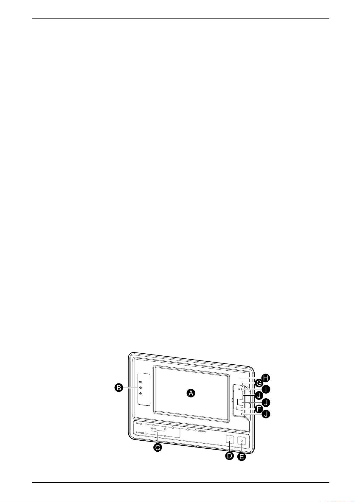
Overview of UPS User Interface
The user interface consists of:
A. Display interface
B. Status LEDs
C. Mimic diagram
D. Inverter ON button
E. Inverter OFF button
F. USB port for export of logs
G. Display reset button
H. Network connection LED:
• Solid green: The system has valid TCP/IP settings.
See Configure the Network, page 21.
• Flashing green: The system does not have valid TCP/IP settings.
• Solid orange: The display is inoperable. Contact Schneider Electric.
• Flashing orange: The system is making BOOTP requests.
See Configure the Network, page 21.
• Alternately flashing green and orange: If the LED is alternately flashing
slowly, the system is making DHCP requests.
See Configure the Network, page 21.
If the LED is alternately flashing rapidly, the system is starting up.
• Off: The display is not receiving input power or the display is inoperable.
I. LED for indication of network connection type:
• Solid green: The system is connected to a network operating at 10
Megabits per second (Mbps).
• Flashing green: The system is receiving or transmitting data packets at 10
Megabits per second (Mbps).
• Solid orange: The system is connected to a network operating at 100
Megabits per second (Mbps).
• Flashing orange: The system is receiving or transmitting data packets at
100 Megabits per second (Mbps).
• Off: One or more of the following exists: The display is not receiving input
power, the cable that connects the system to the network is disconnected,
the device that connects the system to the network is turned off, or the
display is inoperable. Check the connections and if the LED remains off,
contact Schneider Electric.
J. Slots reserved for service.
990–4758D–001 7
160–225 kVA 480 V, 160–200 kVA 400 V Overview of UPS User Interface
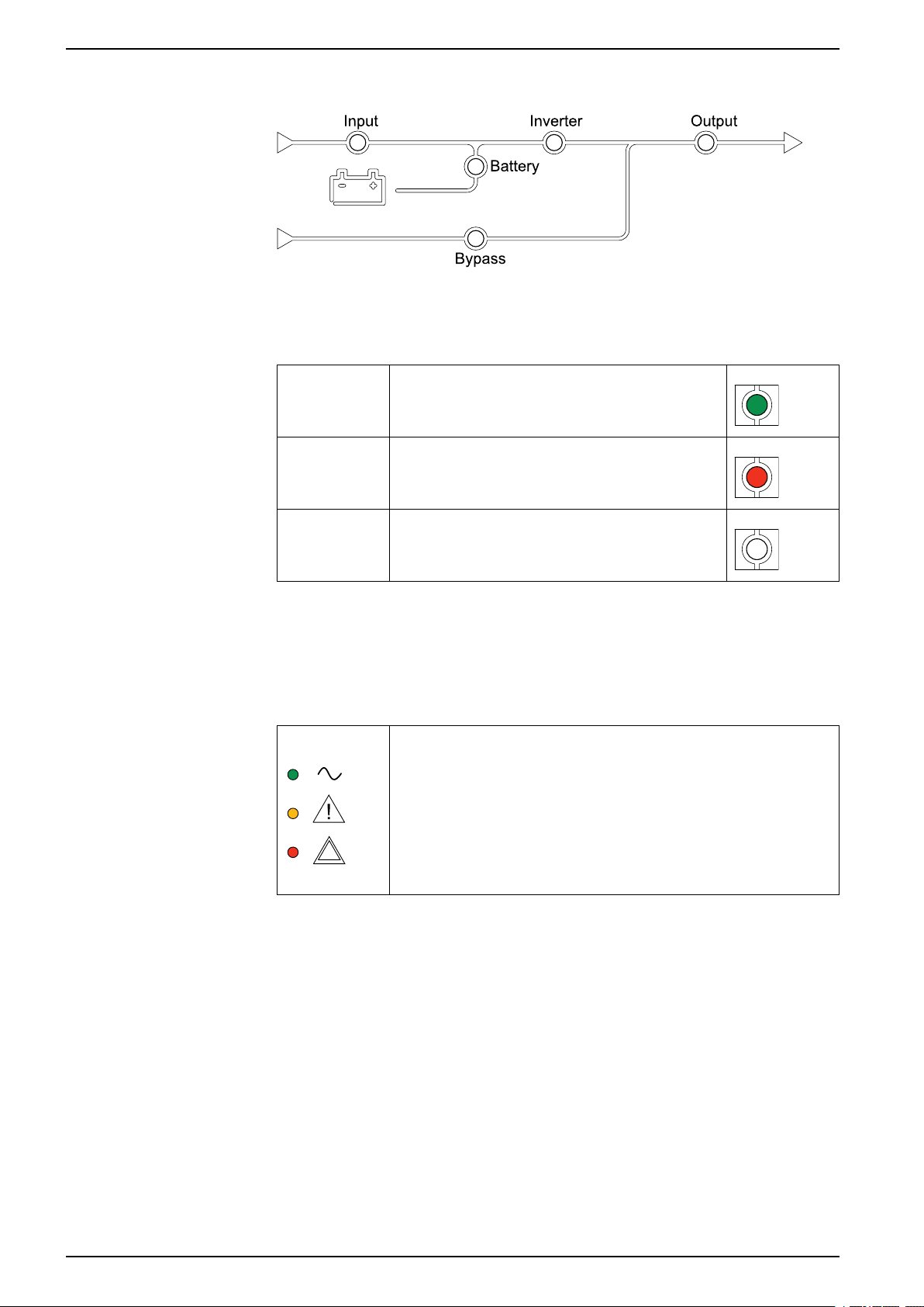
Overview of Mimic Diagram
The mimic diagram shows the power flow through the UPS system, and the status
of the main functions.
Each LED can be in one of the below three states:
Green
Red
Off
Overview of Status LEDs
The status LEDs placed next to the display interface shows the current status of
the UPS system:
The corresponding function is active and OK
The corresponding function is not working
properly
The corresponding function is not active
• Green: The load is protected
• Green + Orange: The load is protected, but the system
reports an alarm at warning level
• Orange + Red: The load is unprotected and the system
reports an alarm at warning level and an alarm at critical
level
• Red: The load is unprotected and the system reports an
alarm at critical level
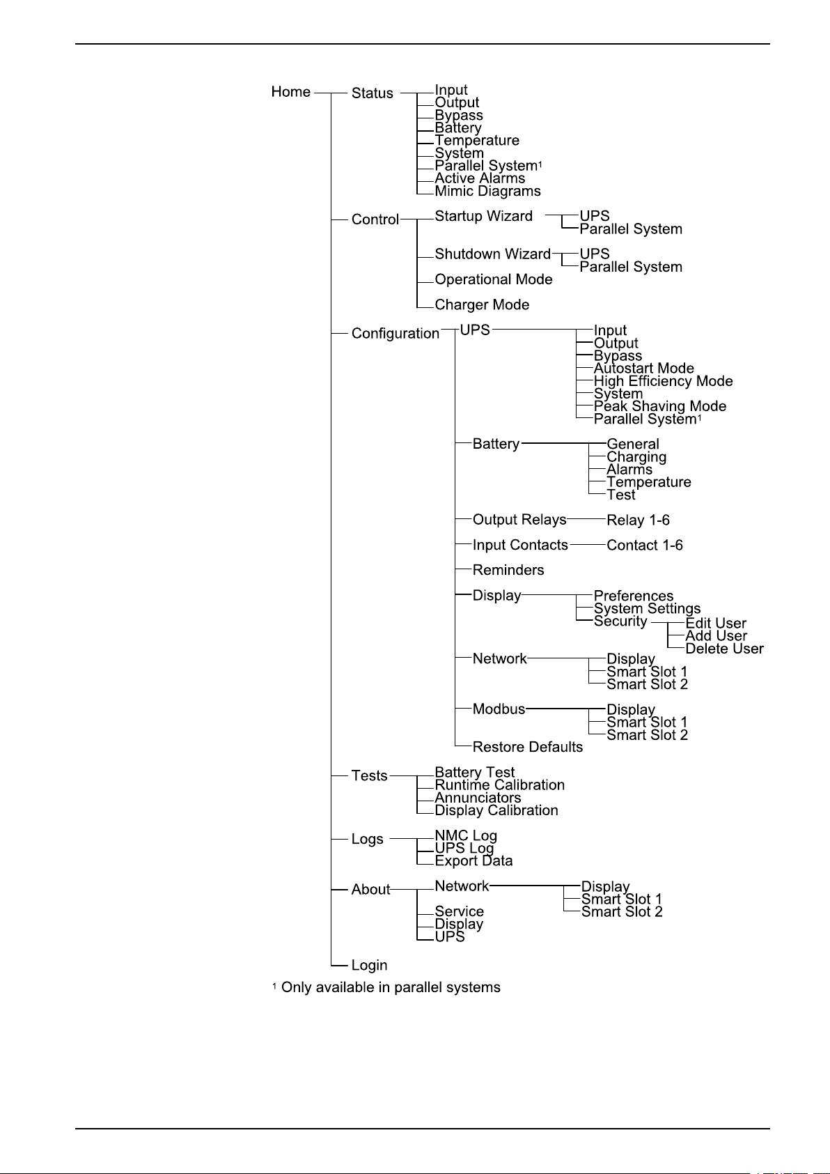
Display Menu Tree
The menu tree is dependent on your system configuration. All screens might not
be available on your UPS
8 990–4758D–001
Overview of UPS User Interface 160–225 kVA 480 V, 160–200 kVA 400 V
NOTE: The control and configuration screens are password-protected.
990–4758D–001 9
160–225 kVA 480 V, 160–200 kVA 400 V Overview of UPS User Interface
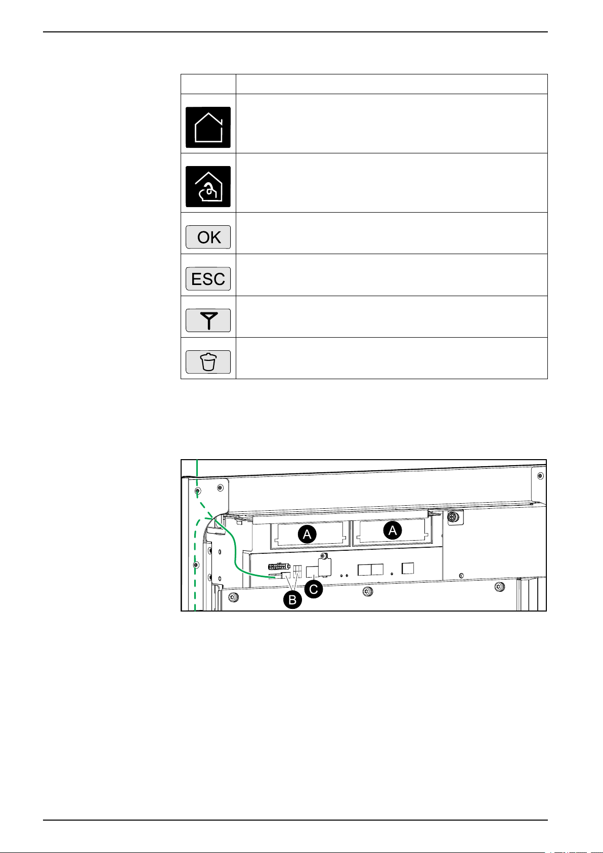
Display Symbols
Symbol
Description
The locked home button appears when the system is locked by a
password protection. Tap this button to go to the home screen of the
display.
The unlocked home button appears when the system has been
unlocked using the password. Tap this button to go to the home
screen of the display.
Tap the OK button to confirm your selections and exit the current
screen.
Tap the ESC button to cancel your changes and exit the current
screen.
Tap the filter button to set up the filters for your logs.
Tap the recycle bin button to clear the log.
Overview of Controller Interface
Front View of Power Cabinet
A. Two Smart Slots for optional Network Management Cards
B. Modbus and modbus dip switch settings
C. Ethernet
10 990–4758D–001

Configuration 160–225 kVA 480 V, 160–200 kVA 400 V
Configuration
Add a New User or Edit an Existing User
1. From the home screen on the display select Configuration > Display >
Security.
2. Select Add User to add a new user or select Edit User to edit an existing user
of the system.
Delete a User
3. In the Name field, type in the name of the user. Complete with Enter.
4. In the Pin field, type in a pin code for the user. Complete with Enter.
5. In the Confirm Pin field, retype the pin code of the user. Complete with Enter.
6. Tap OK to save your settings.
1. From the home screen on the display select Configuration > Display >
Security > Delete User.
2. Browse to the user that you wish to delete using the up and down arrows and
tap OK.
3. Tap Yes to confirm deletion of an existing user of the system.
990–4758D–001 11
160–225 kVA 480 V, 160–200 kVA 400 V Configuration
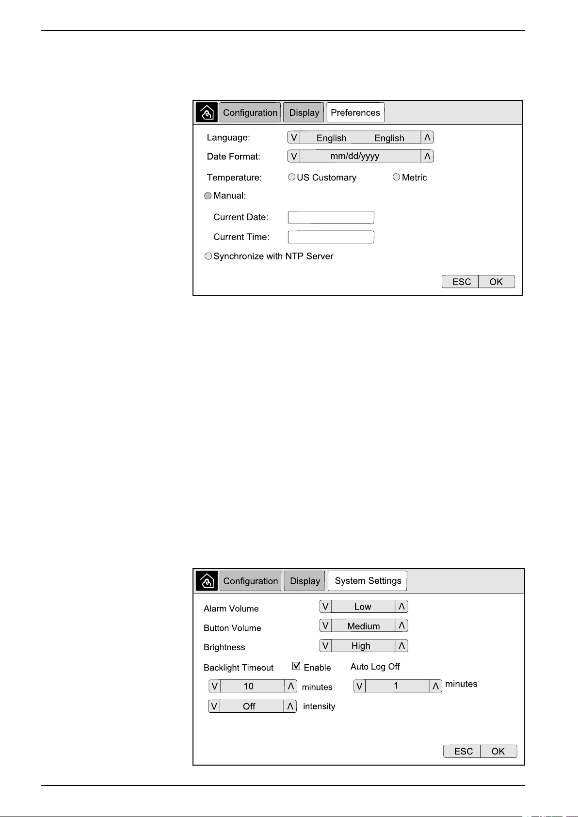
Configure the Display Preferences
1. From the home screen on the display select Configuration > Display >
Preferences.
2. Select the preferred language using the up and down arrows.
3. Select the preferred date format using the up and down arrows.
4. Select the preferred temperature units: US Customary (°Fahrenheit) or Metric
(°Celsius).
5. Set the current date and time using one of the below two methods:
– Set the date and time manually on the display by selecting Manual and
typing the actual date and time and completing with Enter.
– Set the date and time automatically by selecting Synchronize with the
NTP server (Network Time Protocol server).
NOTE: NTP server settings can be configured in the network
management interface via the Web.
6. Tap OK to save your settings.
Configure the Display Settings
1. From the home screen on the display select Configuration > Display >
System Settings.
12 990–4758D–001
Configuration 160–225 kVA 480 V, 160–200 kVA 400 V
2. Set the Alarm Volume. Choose between: Off, Low, Medium, and High.
3. Set the Button Volume. Choose between: Off, Low, Medium, and High.
4. Set the Brightness of the display. Choose between: Low, Medium, and High.
5. Enable or disable Backlight Timeout. If you wish to enable backlight timeout,
set the time limit in minutes for enabling backlight timeout. Choose between:
60, 30, 10, 5, and 1.
6. Set the intensity of the backlight. Choose between: Off, Very Low, Low, and
Medium.
7. Set the time limit in minutes for automatic log off. Choose between: 60, 30, 10,
5, and 1.
8. Tap OK to save your settings.
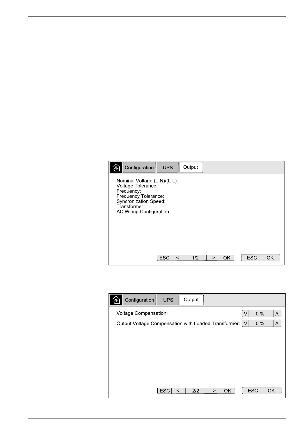
Configure the UPS Output Voltage Compensation
1. From the home screen on the display select Configuration > UPS > Output.
2. Tap arrow to the right to go to the next output configuration screen.
3. Under Voltage Compensation select the preferred voltage compensation for
your system. Choose between –3%, –2%, –1%, 0%, 1%, 2%, or 3%.
NOTE: This setting is shared between all UPSs in a parallel system.
990–4758D–001 13

160–225 kVA 480 V, 160–200 kVA 400 V Configuration
4. Under Output Voltage Compensation with Loaded Transformer select the
preferred output voltage compensation to compensate for load dependent
transformer voltage drop. Choose between 0%, 1%, 2%, or 3%.
NOTE: This setting must be identical for all UPSs in a parallel system.
NOTE: When this setting is set to 0%, the output transformer voltage
compensation is disabled.
5. Tap OK to confirm your setting.
Configure High Efficiency Mode
NOTE: ECO Mode must be enabled by Schneider Electric during service
configuration to make this selection available.
The UPS returns to high efficiency mode after 10 seconds under normal operating
conditions. If an unstable mains forces the UPS to exit high efficiency mode more
than one to ten times (this setting must be configured by Schneider Electric) within
24 hours, the UPS will disable high efficiency mode. An informational alarm will be
generated, and Disabled by system will be shown on the screen Configuration >
UPS > High Efficiency Mode. High efficiency must then be manually reactivated.
1. From the home screen on the display select Configuration > UPS > High
Efficiency Mode and configure the following settings:
a. Select High Efficiency Mode: Choose between Disable, ECO Mode,
ECOnversion, and ECOnversion Harmonics Compensator.
14 990–4758D–001

Configuration 160–225 kVA 480 V, 160–200 kVA 400 V
2. Tap > and configure the schedule settings:
a. Schedule: Select when the system should enter the selected
ECOnversion or ECO mode. Choose between Always, Programmed
and Never.
b. Active Schedules List: If you chose Programmed above, select Enable
and set the time and date for when the system should enter the selected
ECOnversion or ECO mode.
3. Tap OK to confirm your settings.
Enable Peak Shaving Mode
Peak shaving mode allows the UPS to reduce peak power consumed from the
utility/mains supply.
NOTE: Peak shaving mode must be enabled locally by Schneider Electric
during service configuration to make this selection available, but it must be
controlled via a remote software application. Contact Schneider Electric for
more details.
1. From the home screen on the display select Configuration > UPS > Peak
Shaving Mode.
2. Select Enable to enable peak shaving mode.
3. Tap OK to confirm your settings.
990–4758D–001 15
160–225 kVA 480 V, 160–200 kVA 400 V Configuration
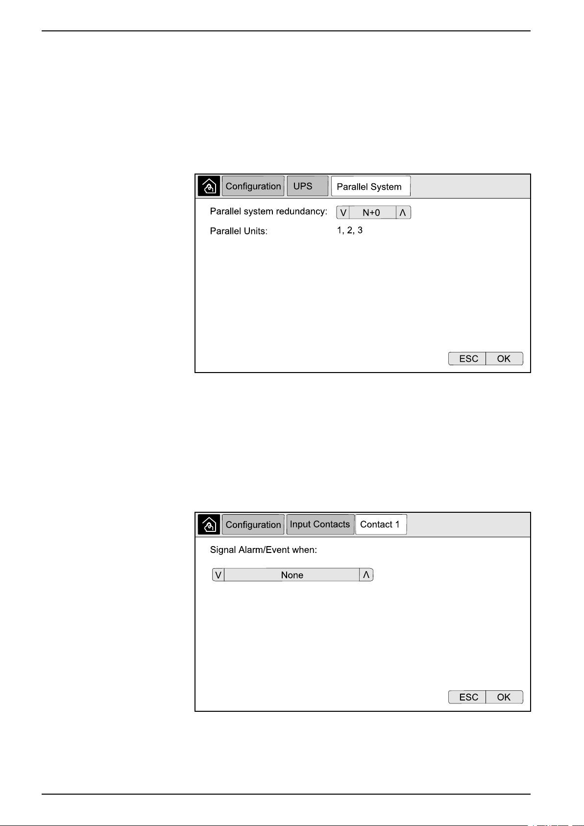
Configure the Redundancy Level of the Parallel System
This procedure sets the redundancy level of your parallel system. The parallel
system can contain up to five UPS units:
• a 4+1 system with four UPS units in capacity and one in redundancy
• a 5+0 system with five UPS units for capacity
1. From the home screen on the display select Configuration > UPS > Parallel
System.
2. Under Parallel system redundancy select the redundancy for your UPS
system. Choose between N+0, N+1, N+2, N+3, N+4.
3. Tap OK to confirm your setting.
Configure the Input Contacts
1. On the display select Configuration > Input Contacts and select the input
contact that you wish to configure.
16 990–4758D–001

Configuration 160–225 kVA 480 V, 160–200 kVA 400 V
2. Choose between the below options:
Custom Input 1: General purpose input. External Battery Monitoring Detected Fault: Input to indicate that
Custom Input 2: General purpose input. Battery Room Ventilation Inoperable: Input to indicate that the
Ground fault: Input to indicate that a ground fault is present. Supplied By Genset: Input to indicate that the UPS is running on
Inhibit Transfer from Static Bypass: When this input is active, and
the system enters requested static bypass or forced static bypass,
the system will be locked in static bypass as long as the input is
active.
External energy storage: major alarm: Input to indicate that the
external energy storage monitor reports a major alarm.
Flywheel inoperable: Input to indicate that the flywheel is
inoperable.
the external battery monitor has detected a fault.
battery room ventilation is inoperable. When the input is active, the
battery charger will turn off.
generator. The battery charge current will be reduced to the value
set by Schneider Electric during start-up.
External energy storage: minor alarm: Input to indicate that the
external energy storage monitor reports a minor alarm.
Force the Charger to Turn Off: Input that forces the charger to turn
off.
Disable High Efficiency Mode: Input to disable the use of high
efficiency mode
3. Tap OK to save your settings.
Configure the Output Relays
1. On the display select Configuration > Output Relays.
2. Select to enable or disable Energized check mode.
– When Energized check mode is enabled the output relays are ON. If a
signal is received or the power supply to the relay is lost, the circuit will
open and the relay will be deactivated.
– When Energized check mode is disabled the output relays are OFF. If a
signal is received, the circuit will close and the relay will be activated.
3. Select the output relay that you wish to configure.
990–4758D–001 17

160–225 kVA 480 V, 160–200 kVA 400 V Configuration
4. Select the function that you wish to use the specific output relay for from the
list below:
Common Alarm: The output is triggered
when any alarm is present.
Battery Operation
1
: The output is triggered
when the UPS is running in battery operation.
Static Bypass
1
: The output is triggered when
the UPS is running in forced static bypass
operation or requested static bypass
operation.
Output Overload: The input is triggered
when there is an overload condition.
Battery is not Working Correctly
1
: The
output is triggered when the batteries are not
working correctly.
Battery Voltage Low
1
: The output is
triggered when the battery voltage is below
the threshold.
Bypass Out of Tolerance
2
: The output is
triggered when the bypass is out of tolerance.
UPS Critical: The output is triggered when a
critical alarm is present.
External Fault: The output is triggered when
a fault external to the UPS is present.
Normal Operation: The output is triggered
when the UPS is running in normal operation.
2
Maintenance Bypass
: The output is
triggered when the UPS is running in
maintenance bypass operation.
High Efficiency Mode: The output is
triggered when the UPS is running in
ECOnversion or ECO mode.
Fan Inoperable: The output is triggered when
one or more fans are inoperable.
1
Battery Disconnected
: The output is
triggered when the batteries have been
disconnected or the battery breaker(s) are
open.
Input Out of Tolerance: The output is
triggered when the input is out of tolerance.
UPS Warning: The output is triggered when a
warning alarm is present.
Parallel Redundancy Lost: The output is
triggered when the specified redundancy has
been lost.
UPS Maintenance Mode: The output is
triggered when the unit output breaker (UOB)
is open.
System Warning: The output is triggered
when a warning alarm is present in a parallel
system.
System Critical: The output is triggered
when a critical alarm is present in a parallel
system.
System informational alarm: The output is
triggered when an information alarm is
present in a parallel system.
5. Set the delay in seconds for the specific output to activate. Select a value
between 0 and 60 seconds.
6. Tap OK to save your settings.
1. Not available when operating as a frequency converter without batteries.
2. Not available when operating as a frequency converter.
18 990–4758D–001
 Loading...