


SVR-950

Premium Security
Digital Video Recorder SVR-1650/1640/950 User’s Manual
Thank you for purchasing a Samsung Digital Video Recorder.
Before attempting to connect or operate this product,
please read these instructions carefully and save this manual for future use.
ENGLISH


IInnttrroodduuccttiioonn
Thank you for purchasing the SVR-1650/1640/950.
This is a user manual for SVR-1650/1640/950. Before product installation and operation, please become
thoroughly familiar with this user manual and other manuals referenced by this manual.
This user manual and the software and hardware described here are protected by the copyright law.
Therefore, with the exception of copying for general use within the copyright law, copying and reprinting the
user manual, either partially or in its entirety, or translating it into another language without the consent of
Samsung Techwin, Inc. is prohibited.
This specification may be changed without prior notice for improvement of product performance.
Product warranty and limits of responsibility
The manufacturer does not assume any other responsibility concerning the sale of this product and does not
delegate any right to a third party to take any responsibility on its behalf. Product warranty does not cover
cases of accidents, negligence, alteration, misuse or abuse. In addition, no warranty is offered for any
attachments or parts not supplied by the manufacturer.
The warranty period for this product will be for 2 years from the date of purchase. The following cases are
not covered by the warranty and payment is required for repairs.
Malfunction due to negligence in handling by the user
Deliberate disassembly and replacement by the user
Connection of a power source other than a properly rated power source
Malfunction caused by natural disasters (fire, flood, tidal wave, etc.)
Replacement of expendable parts(HDD, FAN, etc.)
Warranty only refers to the warranty covering products that have been paid for.
After expiration of the warranty period (2 years), examination and repair will be provided for a fee. Even
during the warranty period, repair and examination of items outside the preceding warranty scope will
require a payment.
Please inquire at the point of purchase or the local service center for repairs requiring a payment.
1

Table of Contents
Introduction ...............................................................1
Product warranty and limits of responsibility ...........................................1
Chapter 1. Safety Cautions ..............................................5
Symbols displayed for each item .........................................................5
Chapter 2. Summary .....................................................8
2.1 Features ...............................................................................8
2.2 Components ........................................................................11
2.3 Name and Function of Each Part.................................................11
2.3.1 Front panel ...........................................................................11
2.3.2 Back connector terminals ............................................................14
2.3.3 Remote Controller....................................................................15
2.4 Product specification ....................................... ........................16
Chapter 3. Installation method .......................................20
3.1 Overall connection..................................................................20
3.1.1 Front connection method ...........................................................20
3.1.2 Back connection method ............................................................21
3.2 Detailed connection ................................................................ 22
3.2.1 Rack mount...........................................................................22
3.2.2 Video/Audio connection.............................................................23
3.2.3 External connector ...................................................................25
Chapter 4. Operation method ........................................32
4.1 Preoperation inspection items...................................................... 32
4.2 Connection of power supply ......................................................32
4.3 Live screen ..........................................................................32
4.3.1 FUNCTION screen display .........................................................33
4.3.2 Single channel screen display........................................................33
4.3.3 Multi screen display..................................................................34
4.4 Recording ........................................................................... 35
4.4.1 General recording ....................................................................35
4.4.2 Scheduled recording ..................................................................35
4.5 Search ............................................................................... 36
2

SVR-1650/1640/950 User Manual
4.5.1 Time search .......................................................................... 36
4.5.2 Event search ......................................................................... 37
4.5.3 Log search............................................................................ 38
4.6 Recording file playback .............................................................38
4.6.1 Jog dial / shuttle ring............................................................... 39
4.7 Live / Playback screen conversion.................................................39
4.8 Digital zoom ........................................................................40
4.9 Copy .................................................................................40
4.9.1 SLiM Player .......................................................................... 42
4.10 PTZ ................................................................................44
4.10.1 PTZ adjustment .................................................................... 44
4.10.2 Preset setup ......................................................................... 44
4.10.3 Preset utilization .................................................................... 45
4.10.4 Using OSD for the Speed Dome Camera....................................... 45
4.11 Quick setup ........................................................................46
4.12 PIP .................................................................................47
4.13 System information ................................................................48
4.14 SPOT...............................................................................49
Chapter 5. Setup method............................................. 50
5.1 Menu organization ..................................................................50
5.2 Initial value setup ...................... .............................................52
5.3 Operation description...............................................................60
5.4 FUNCTION menu ................................................................. 61
5.4.1 LIVE/PLAY mode .................................................................. 61
5.4.2 FUNCTION operation description ................................................. 61
5.5 Menu screen description ............................................................65
5.6 Screen setup.........................................................................66
5.6.1 Screen................................................................................. 66
5.6.2 Sequencing............................................................................ 67
5.6.3 Display................................................................................ 70
5.6.4 Covert.................................................................................71
5.6.5 SPOT ................................................................................. 71
5.7 Record setup ........................................................................72
5.7.1 Record mode......................................................................... 72
5.7.2 Record program...................................................................... 74
5.7.3 Recording time table ................................................................ 75
5.8 Event setup..........................................................................76
5.8.1 Event ................................................................................. 76
5.8.2 Motion detection..................................................................... 77
3

5.8.3 Relay...................................................................................78
5.8.4 TEXT .................................................................................78
5.9 Communication setup ..............................................................79
5.9.1 NETWORK ..........................................................................79
5.9.2 RS-232.................................................................................80
5.9.3 RS-422/485 ...........................................................................81
5.9.4 E-MAIL ...............................................................................82
5.10 System setup....................................................................... 83
5.10.1 System ...............................................................................83
5.10.2 HDD.................................................................................86
5.10.3 Password.............................................................................87
5.10.4 Date setup...........................................................................88
5.10.5 PTZ ..................................................................................89
5.11 Video recording search....... ..................................................... 90
5.11.1 Time search .........................................................................90
5.11.2 Event search.........................................................................91
5.11.3 Log search...........................................................................91
5.12 Copy ............................................................................... 92
5.13 Exit ................................................................................93
Chapter 6. Network viewer program ................................94
6.1 Introduction......................................................................... 94
6.1.1 System requirements..................................................................94
6.1.2 Program installation ..................................................................95
6.2 DVR MANAGER Function ....................................................... 96
6.3 VIEWER screen function..........................................................99
6.3.1 Name for each function.............................................................99
6.3.2 Image display section ..............................................................100
6.3.3 Page control section ...............................................................100
6.3.4 DVR status display section........................................................ 104
6.3.5 Main button section ............................................................... 105
6.3.6 List display section.................................................................109
6.3.7 PTZ control section ...............................................................110
6.3.8 Additional functions................................................................111
Chapter 7. Trobleshooting ..........................................112
Product Specifications ................................................................ 114
4
CChhaapptteerr 11.. SSaaffeettyy CCaauuttiioonnss
Symbols displayed for each item
Warning
Refers to information u sers ne ed to know in order to pre vent serio us in jury or deat h.
Caution
Provides information users need to know in order to prevent minor injury or product damage.
Before installation
9 Verify the supplied voltage (AC100V~AC240V) before connecting the power supply.
9 Make sure the power supply is off before installation.
9 Do not install in a very humid environment. Doing so may cause an electric shock or fire.
9 Make sure ground line is connected to reduce electric shock risk.
During operation
9 Do not open the product cover except qualified personnel or system installer.. Opening the
9 Do not plug multiple appliances into one power outlet. Doing so may cause fire.
9 Do not place dishes containing water or heavy objects on the product. Doing so may cause a
9 Do not use in areas containing inflammable materials like propane gas and gasoline or in areas
9 Do not touch the power line with a wet hand. Doing so may cause an electric shock.
9 Do not insert a hand into the opening of the DVD. Doing so may cause an injury.
9 Make sure conduction materials do not enter the cooling ventilator opening.
product cover may cause an electric shock.
malfunction.
that generate dust. Doing so may cause an explosion or fire.
5

9 Do not apply excessive force when pulling on the power cord. Damaging the cord may cause
an electric shock or fire.
9 Random replacement of built-in battery by other types of batteries may cause explosion.
9 The battery shall be replaced by the same battery.
9 The used batteries shall be disposed carefully because they can cause environment pollutions.
Dismantling and cleaning
9 Do not dismantle, repair or modify the product deliberately. Doing so may cause a damage, an
electric shock or an injury.
9 Do not use water, thinner or organic solvent for cleaning the product exterior. Doing so may
cause a malfunction or an electric shock. Use a dry cloth to clean the exterior.
During installation
9 To get adequate ventilation, install the product with at least 15cm of space between the
cooling ventilation opening and a wall.
6
9 To prevent falling, install the product in a flat area . Dropping the product may cause an injury
or a malfunction.
9 Avoid areas exposed to sun light or heat since they may cause deformation or a malfunction.
9 If a camera is installed while the DVR is recording, image in another channel may be
disrupted. Start the storage after installing the camera is recommended.
During use
9 Make sure the product is not exposed to shocks or shaking when using the product or during
moving.
9 Do not move the product while it is in operation, and apply strong shocks to the product or
throw the product.
9 If hard disk drives other than those recommended are used additionally, abnormal operation
may occur. Inquire at the point of purchase of the product before installing such a hard disk
drive.
9 Product warranty will not cover deliberate additional use of such hard disk drives.
9 This product is a supplementary rather than primary means for preventing fire and theft. Our
company is not responsible for incidence of incident or damage that may occur.

SVR-1650/1640/950 User Manual
INFORMATION
This equipment has been tested and found to comply with limits for a Class A digital device, pursuant to part
15 of the FCC Rules. These limits are designed to provide reasonable protection against harmful
interference when the equipment is operated in a commercial environment. This equipment generates, uses,
and can radiate radio frequency energy and, if not installed and used in accordance with the instruction
manual, may cause harmful interference to radio communications. Operation of this equipment in a
residential area is likely to cause harmful interference in which case the user will be required to correct the
interference at his own expense.
Correct Disposal of This Product
(Waste Electrical & Electronic Equipment)
(Applicable in the European Union and other European countries with separate
collection systems) This marking shown on the product or its literature, indicates
that it should not be disposed with other household wastes at the end of its
working life. To prevent possible harm to the environment or human health from
uncontrolled waste disposal, please separate this from other types of wastes and
recycle it responsibly to promote the sustainable reuse of material resources.
Household users should contact either the retailer where they purchased this
product, or their local government office, for details of where and how they can
take this item for environmentally safe recycling. Business users should contact their
supplier and check the terms and conditions of the purchase contract. This product
should not be mixed with other commercial wastes for disposal.
Samsung Techwin cares for the environment at all product manufac
turing stages to preserve the environment, and is taking a number
of steps to provide customers with more environment-friendly prod
ucts.The Eco mark represents Samsung Techwin s will to create en
vironment-friendly products, and indicates that the product satisfies
the EU RoHS Directive.
1
7

CChhaapptteerr 22.. SSuummmmaarryy
This product is a digital video recorder that digitizes 16 channels of video input and stores it in the
built-in hard disk drive. Product functions can be setup conveniently using the mouse and buttons on
the front panel.
Samsung SVR-1650/1640/950 is a digital image recorder that can be used as security equipment in
banks, apartments, and government and public offices. It is a stand-alone product with proven
performance and stability. Since a hard disk drive is used for storage instead of a video tape, high quality
can be maintained for even repetitive recordings and fast retrieval of digital files is also possible. This is
a user friendly digital device with a diverse array of functions including a high quality video, a large
capacity storage, perfect simultaneous implementation of recording/playback/backup functions, motion
detection, PTZ (Pan, Tilt, Zoom) control function, password setup, real time voice data storage, an
event list with up to 10,000 events and log file storage.
2.1 Features
Monitoring Screen
Vivid live video with high image quality is realized and various observation screens are provided for
each channel.
Implementation of real time MPEG-4 video
y NTSC : 480 frames(SVR-1650)/120 frames(SVR-1640/950)
y PAL : 400 frames(SVR-1650)/100 frames(SVR-1640/950)
Various observation screen modes:
y SVR-1650/1640 : Single, 4 DIVISION, 9 DIVISION, 16 DIVISION
y SVR-950 : Single, 4 DIVISION, 9 DIVISION
Automatic screen conversion (AUTO)
Various monitor output supported [3 Composite (including 1 Spot), 1 VGA, 1 RCA]
Pan, Tilt, Digital Zoom, PIP(Picture in Picture; view screen within a screen)
Voice recording
Real time voice input and recording function is provided.
Real time, simultaneous recording of 4 channels voice input possible
(1, 2, 3, 4 channel fixed)
Input: 4 channels (4 back side), Output: 2 (1 back side/ 1 front side)
Simultaneous recording and playback is possible
8

SVR-1650/1640/950 User Manual
Video recording
High image quality MPEG4 video recording is possible. Up to 480 frames(SVR-1650)/120
frames(SVR-1640/950) per second of recorded video can be stored and pre-event recording can be done for
up to 5 seconds before an event occurs. In addition, privacy is protected by the COVERT (image hiding)
function.
MPEG-4 video recording with high image quality
4 steps video recording resolution setup to adjust storage capacity
Multiple recordings possible for manual & events or schedule & events
Simultaneous execution of the following 4 functions:
recording/playback/backup/network.
Easy setup of video recording resolution and motion detection for each channel.
Video recording setup of up to 480(NTSC : SVR-1650)/120(NTSC :SVR-1640/950)
or 400(PAL : SVR-1650)/100(PAL : SVR-1640/950) frames per second possible
(352×240 or 352x288(CIF) based),
2
Manual and scheduled recording possible
Video loss detection function
Record events(sensor, video loss, motion detection and text) in the event list
Up to 5 seconds of pre-alarm event recording for each channel possible
Search/Playback
A wide range of convenient functions for search and playback are provided.
Playback by time, by date, by channel
Convenient search using the mouse
Still image step up/down playback
Playback based on EVENT(sensor, video loss, motion detection and text) list
Easy search using the remote controller and jog/shuttle
Digital zoom in playback screen
9

Storage device
A built-in hard disk drive is provided. User may also select to use DVD+RW and USB memory for backup.
Standard storage: Built-in hard disk drive
Various backup devices available: DVD+RW and USB memory
Network
Various networks including LAN, xDSL is supported. Key functions of the product may be manipu
lated easily and maintained remotely using the dedicated viewer for PC.
If an EVENT occurs, transmit by E-mail through TCP/IP, DHCP
Live image viewing from a remote location is possible (entire or 4 DIVISION screen
selection is possible)
PC playback, storage, search function and DVR control function using the network
viewer is possible
Search and playback by time or by event from a remote location is possible
10/100Mbps Ethernet/xDSL support
Multiple DVR connection
Others
GUI and mouse for user convenience
Convenient firmware upgrade function using USB memory
PTZ CONTROL (SPEED DOME), PRE-SET support
Multiple language support: Korean, English, Italian, Spanish, Japanese, etc.
Video recorded image backup function (still images/video) using the USB port
16 DVRs may be controlled conveniently using one remote controller
10
SVR-1650/1640/950 User Manual
3
12 16 13 14
20 21 22 23
27
R
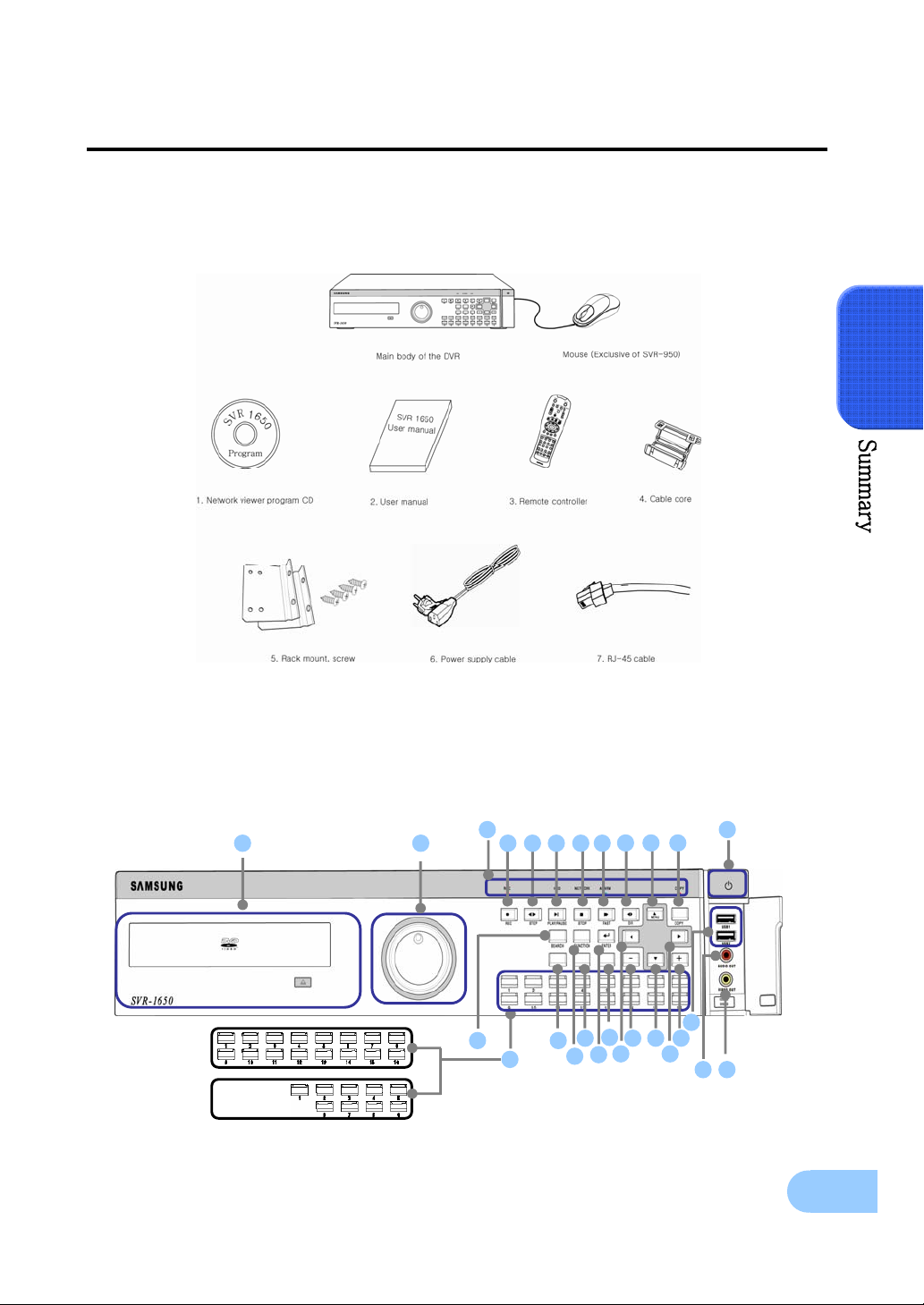
2.2 Components
DVR package contains the main body and the following accessories. Please verify whether all accessories are
included at the time of purchase. If any accessory is missing, inquire at the point of purchase.
2
2.3 Name and Function of Each Part
2.3.1 Front panel
SVR-1650/1640
SV
-950
1
2 5 6 7 8 9
18
19
10 11
17
15
4
24
25 26
11
Backup(Copy) section
Category Function
1. DVD-Multi : DVR for
backup
Used to backup recorded/stored images on DVD+RW/CD-RW
media.
Jog/shuttle section
Category Function
Menu setup values can be adjusted and STEP function can be
2. JOG/SHUTTLE
controlled with JOG. SHUTTLE can be used for moving items
between menus, increasing or decreasing playback speed, changing
playback direction and for controlling PTZ.
Display section
Category Function
REC display LED Indicates whether recording is in progress.
HDD display LED Indicates whether hard disk drive is in operation.
3.
NETWORK display LED Indicates whether network is in connection.
ALARM display LED Indicates whether event is in detection.
COPY display LED Indicates whether COPY is in progress.
Power supply section
Category Function
4. Stand-by button Turn product ON or OFF.
Playback and recording section
Category Function
5. REC Start or stop the manual mode video recording.
6. STEP Start 1 Frame playback.
7. PLAY/PAUSE Start playback or pause momentarily.
8. STOP Stop playback and return to live screen mode.
9. FAST Playback is carried out faster than the normal playback speed.
10. DIR Used to change the playback direction.
12
SVR-1650/1640/950 User Manual
Function button section
Category Function
11. ▼
MENU
15. + Used to increase value to be setup or move to another page.
16. - Used to decrease value to be setup or move to another page.
17.COPY
18. SEARCH Select data search mode.
19. MULTI Convert to a divided screen.
20. FUNCTION Display the LIVE screen menu for FUNCTION.
21. PTZ Select PTZ mode.
22. ENTER Store or execute the select options.
23. ESC. Return to the previous stage menu.
12. ▲
13. ◀
14. ▶
Used for movement in the lower direction
Used for movement in the upper direction.
Used for movement to the left
Used for movement to the right
Display the copy menu. Store data in DVD+RW and USB Memory
Stick at the preset time.
USB, Audio/Video section
2
Category Function
24. USB1, USB2, USB3 Connection port for mouse, USB Memory Stick and DVD+RW
25. AUDIO OUT Output port for connecting speaker.
26. VIDEO OUT Output port to connect TV monitor.
Channel button section
Category Function
27. CH1~CH16 (SVR-1650/1640) /
CH1 ~ 9 (SVR-950)
Display selection button of each channel (Live/Playback),
Select single mode and PIP channel.
13
12 13 14 15 18 17 16
3
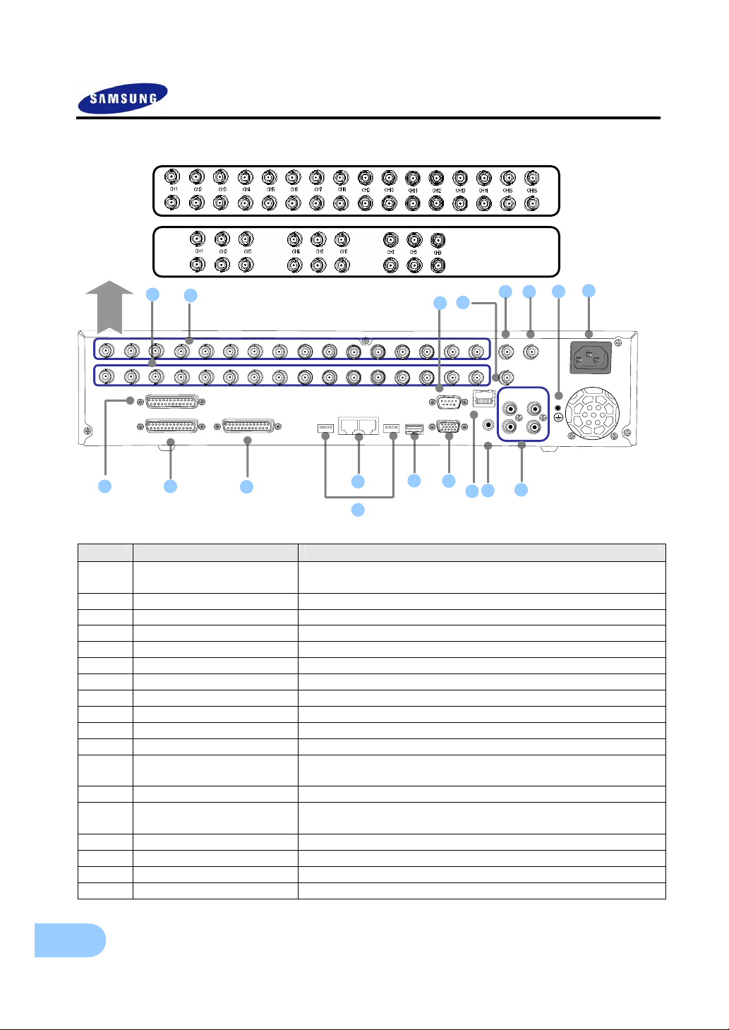
2.3.2 Back connector terminals
SVR-1650/1640
SVR-950
6
1
H
C
T
E
N
R
E
H
T
E
IO
D
U
A
T
U
O
5 6 7
A
1
R
IT
M
M
N
O
B
O
O
R
IT
N
O
A
2
R
IT
M
N
O
O
2
IO
IN
D
U
1
A
IO
IN
D
U
A
4
IO
IN
D
U
A
3
IO
IN
D
U
A
2
1
1
H
C
2
H
C
3
H
C
4
H
C
5
H
C
6
H
C
7
H
C
8
H
C
9
H
0
1
C
H
C
1
1
H
C
2
1
H
C
13
H
C
R
4
-
S
2
2
/
4
8
SENSOR IN
RELAY OUT
9
10
CONSOLE
11
E
T
5
M
R
1
M
R
2
E
T
3,4
B
S
U
1 2 3 41 2 3 4
4
4
1
H
C
5
1
H
C
-2
S
C
32
R
A
G
V
No. I/O terminal names Function
CH1~16
1
(SVR-950: CH1~9)
BNC input connector terminal for the camera.
2 LOOP OUT BNC output (loop) connector terminal for the camera.
3 RS-232C RS-232C terminal.
4 MONITOR A2 BNC connector terminal for monitor output.
5 MONITOR A1 BNC connector terminal for monitor output.
6 MONITOR B BNC connector terminal for SPOT monitor output.
7 GROUND Ground terminal for DVR main body and external equipment.
8 POWER IN Socket for AC100V ~ AC240V power supply cord.
9 SENSOR IN Input terminal for external alarm sensor.
10 RELAY OUT Relay output terminal.
11 CONSOLE Auxiliary port
12 RS-485/422
Terminal to connect expansion controller, speed dome camera,
SRX-100B connector.
13 TERMINATION Switch for RS-485 termination resistor setup.
14 USB
Terminal to connect external equipment
(DVD+RW, CD-RW, etc.).
15 VGA OUTPUT Output port to connect the PC monitor.
16 ETHERNET(Main) LAN connection terminal.
17 AUDIO OUT Terminal for speaker output.
18 AUDIO IN Terminal for microscope input.
8
14
SVR-1650/1640/950 User Manual
Refer to ‘Chapter 3. Installation method’ and ‘Chapter 4. Operation method’ for
detailed description about setup and utilization.
Because console terminal is a reserve terminal , a user may not connect it
arbitrarily.
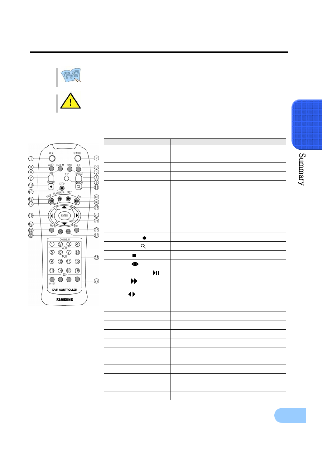
2.3.3 Remote Controller
Button names Function
1. MENU Menu screen conversion
2. STATUS System setup information display
3. AUTO Automatic screen conversion
4. D.ZOOM Digital zoom execution
5. SPOT SPOT monitor screen conversion
6. AUX Auxiliary
7. PTZ PTZ mode conversion
8. COPY
9. PIP View picture in picture
10. RECORD( ) Start or stop general video recording
11. SEARCH( ) Search menu display
12. STOP( ) Cancel playback mode
13. STEP( ) Playback 1 frame
14. PLAY/PAUSE( ) Playback and pause
15. FAST( ) High speed playback
16. DIR( )
17. (▲) Move cursor up in the setup menu
18. (▼) Move cursor down in the setup menu
19. (◀) Move cursor to the left in the setup menu
20. (▶) Move cursor to the right in the setup menu
21. ENTER Setup value selection, execution
22. MULTI Divided screen selection
23. (-) Reduce setup value, move to another page.
24. (+) Increase setup value, move to another page.
25. ESC Cancel the setup, exit the menu
26. Channel button Camera channel selection
27. Remote controller ID Remote controller ID selection
2
Copy menu display, store the image through
USB
Change playback direction
(forward direction or reverse direction)
15
2.4 Product specification
Video
Items Specification
Input method Composite input 16 channels(SVR-1650/1640) / 9 channels(SVR-950)
Video input level 1.0 Vp–p, composite
NTSC
- SVR-1650/1640 : 480 frames/sec
Live screen presentation
speed
Live screen resolution
Monitor output
VGA output
(PC monitor)
PIP screen
- SVR-950 : 270 frames/sec
PAL
- SVR-1650/1640 : 400 frames/sec
- SVR-950 : 225 frames/sec
NTSC : 720(horizontal) × 480(vertical) pixels, if entire screen selected
PAL : 720(horizontal) × 576(vertical) pixels, if entire screen selected
1.0Vp–p Composite, 75Ω output
Back : 2 terminals(BNC : composite),
1 terminal(BNC : SPOT composite)
Front : 1 terminal(RCA : composite)
Loop(BNC) 16 CH(SVR-1650/1640) / 9CH(SVR-950) output
RGB output
PIP screen size: 240×160(Fixed on left top side)
PIP screen organization: Small live screen inside the live entire screen
Audio
Items Specification
Audio 4 channel audio input
Line input level 1.0V / 20kΩ
Line output level 1.0V / 1kΩ
Storage method PCM method
Electric Specification
Items Specification
Power supply AC 100V ~ 240V, (50/60Hz), Max, 2A
Power consumption About 75W (if one hard disk drive used)
Alarm
Items Specification
Input 16 channels(SVR-1650/1640) / 9channels(SVR-950)
Output
16
4 relay outputs(video loss, power off, motion detection, sensor)
user setup possible
SVR-1650/1640/950 User Manual
Connector terminals
Items Specification
Video input BNC(SVR-1650/1640: 16, SVR-950: 9)
Loop output BNC(SVR-1650/1640: 16, SVR-950: 9)
Monitor output BNC(2), RCA(Front 1)
SPOT Monitor output BNC(1)
VGA output
(PC monitor)
Audio RCA input (4), RCA output (2 - including the front)
25 pin DSUB Sensor input (SVR-1650/1640: 16, SVR-950: 9), relay output(4)
Dual RJ-45 RS-422/485(2)
9 pin DSUB RS-232C(1)
USB port Front (2), back (1)
RJ-45 Network (Ethernet)-10/100M bps supported
15 pin VGA
Controller
Item Specification
Remote controller Infrared LED(Max. 5m)
Mouse(USB) Menu setup and DVR setup handling possible
Dedicated controller SCC-3100A(RS-485)
2
Hard disk drive
Items Specification
Max. no. of mounts 4
Basic mount 1 (built-in)
Hard disk drive type EIDE(ULTRA DMA-133)
Min. speed 7200rpm
Recommended product Maxtor series, Samsung Electronics
The recommended models are as follows.
Model HDD capacity Buffer Manufacturer
6L160P0 160G 8M Maxtor
7L250R0 250G 16M Maxtor
7H500R0 500G 16M Maxtor
SP1644N 160G 2M Samsung Electroics
※ If other products are used, HDD operation error may occur.
Exterior appearance
Items Specification
Material Metal case, Front(aluminum, plastic)
Dimensions 430(width) × 465(length) × 88(height) mm
Weight About 8.9kg(1 HDD)
17
Operation environment
Items Specification
Operating temperature
Storage temperature
Humidity
5°C ∼ 40°C
–10°C ∼ 60°C
30% ∼ 90%
Video recording
Items
SVR-1650 SVR-1640/950
Specification
Compression method MPEG-4
Video recording method 2 video recording modes: schedule & event, manual & event
30 frames/sec
60 fields/sec
120fields/sec
25 frames/sec
50 fields/sec
100 fields/sec
Maximum number of
frames per second
(resolution)
Picture quality
NTSC(704×480) : 120 frames/sec
NTSC(704×240) : 240 fields/sec
NTSC(352×240) : 480 fields/sec
PAL(704×576) : 100 frames/sec
PAL(704×288) : 200 fields/sec
PAL(352×288) : 400 fields/sec
4 levels of picture quality: User setup possible
(SUPER, HIGH, MID, LOW)
Pre Alarm Setup possible within maximum 5 seconds
Post Alarm Setup possible within maximum 5 minuets
Countries using NTSC : USA, Canada, Japan, Korea, Taiwan, Mexico, etc.
Countries using PAL : Australia, Austria, Belgium, China, Denmark,
Finland, Germany, England, Nederland, Italy, Kuwait,
Malaysia, New Zealand, Singapore, Spain, Sweden,
Switzerland, Thailand, Norway, etc.
Network
Items Specification
Compression method : MPEG-4
General
PC requirements
Connection method: Dedicated viewer
Supported protocols: TCP/IP, DHCP
Supported interfaces: Ethernet(10M/100M bps), xDSL
CPU: Pentium IV 3.0GHz or higher (Hyper Threading recommended)
Memory: Over 512MB recommended
Video Card : Memory over 128MB recommended
Hard Disk : Size larger than 120GB is recommended
OS: Windows 2000 or higher versions recommended
Monitor: Over 1,024×768 pixels(1280×1024 recommended)
LAN interface: 10/100 Base–T Network card
18
SVR-1650/1640/950 User Manual
Copy
Item Specification
Digital copy
Only DVD+RW, CD-RW media may be used.
DVD+RW (Built-in DVR)
External USB memory
Search and playback
Item Specification
Search by time : year, month, day, hour, minute, second
Search mode
Log file
Event item Alarm, motion detection, video loss
Playback speed and
direction
High speed search Fast forward (×2, ×4, ×8, Max), reverse(×2, ×4, ×8, MAX)
Pause and frame playback
Search by channel : For each channel
Search by event : sensor, motion detection, video loss and text
Power ON/OFF, video recording start/stop, display miscellaneous
information
Forward direction, reverse direction
Playback screen pause function, function to reproduce one frame at a
time from the paused state
2
Password
Item Specification
2 stage password
Accessories
Item Specification
Supplied accessories
8 digit numeric code
Admin: Control all functions
User: Connect through the network
Network viewer program CD
User manual
Quick guide manual
Remote controller
Mouse (Exclusive of SVR-950)
Cable core
RJ-45 cable (2 cable)
Rack mount and screw
Power supply cable
19
T
R
CChhaapptteerr 33.. IInnssttaallllaattiioonn mmeetthhoodd
3.1 Overall connection
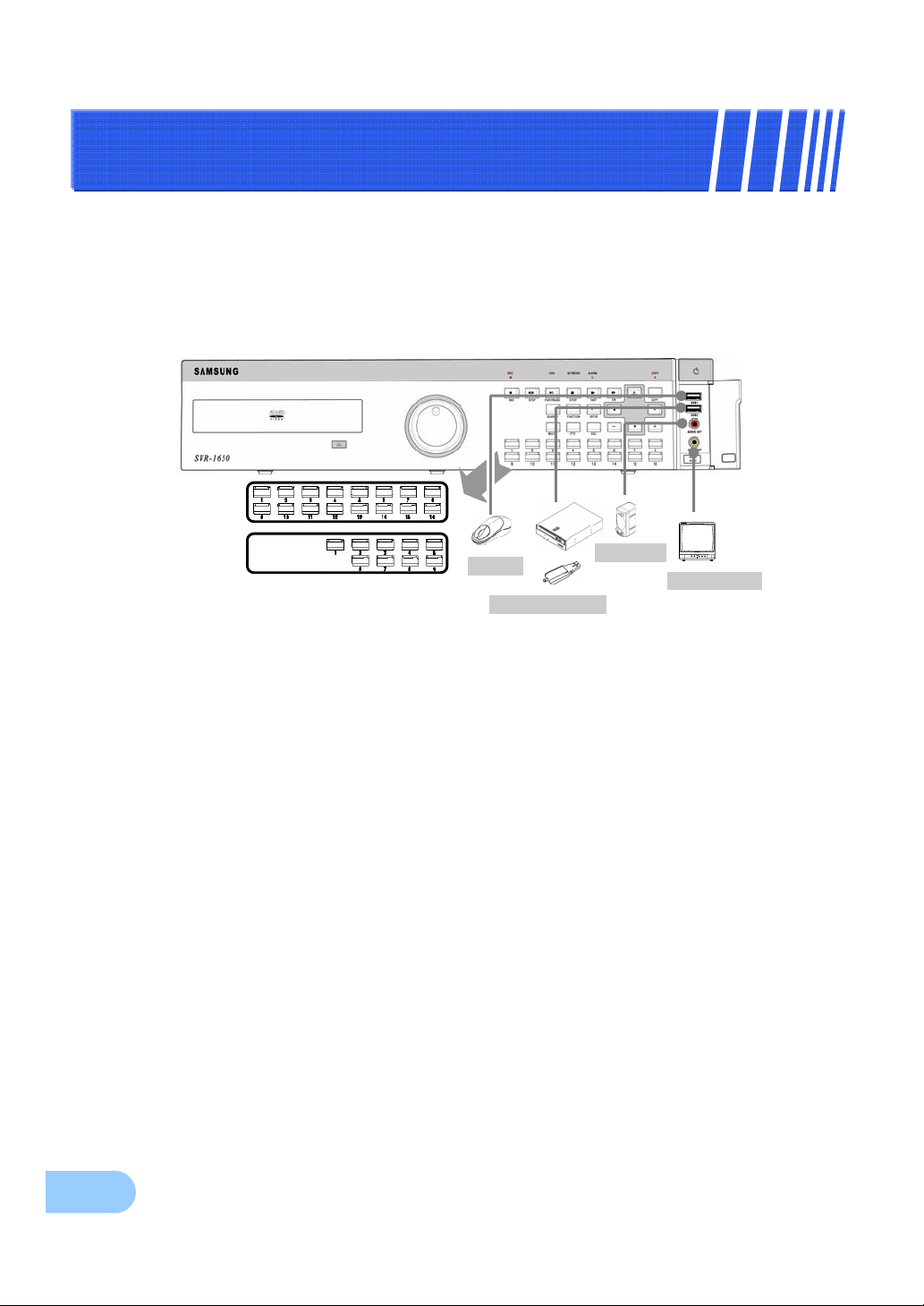
3.1.1 Front connection method
Connection organization diagram for DVR front side terminals are as follows.
SVR-1650/1640
SV
-950
*Use only DVD+RW/CD-RW Media
Mouse
Memory stick
Speaker
V Monitor
20
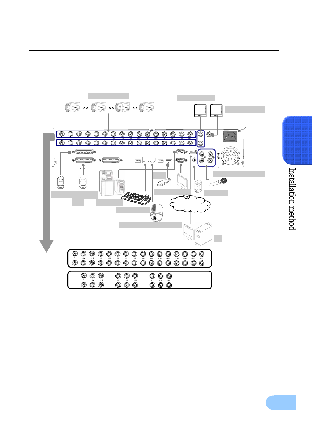
3.1.2 Back connection method
SVR-1650/1640/950 User Manual
The organization chart for
Camera 1~16
1
H
C
C
4
H
C
3
2
H
H
C
SENSOR IN
RELAY OUT
Sensor Warning
LED
DVR
and monitors,
6
H
C
5
H
C
H
C
CONSOLE
ATM/POS
CCTV
cameras and external devices is as follows
9
H
C
8
H
C
7
10
H
C
R
TE
12
H
C
11
H
C
R
1
M
13
H
C
4
S
-
/
2
4
2
5
8
2
M
R
TE
U
1 2 3 41 2 3 4
USB
VGA Monitor
SCC-3100A
Speed Dome Camera
Main Monitor
15
16
H
H
C
C
14
H
C
H
ET
-232C
S
R
3,4
B
S
A
G
V
LAN/WAN
ITO
N
O
M
ITO
N
O
M
U
A
T
E
N
R
E
IO
D
U
A
U
A
T
U
O
SPOT Monitor
ITO
N
B
R
O
A
R
M
1
A
R
2
IO
D
U
2
IN
A
IO
D
1
IN
IO
D
U
4
IN
A
IO
D
3
IN
Audio(Line Input)
Speaker
PC
.
3
SVR-1650/1640
SVR-950
21
3.2 Detailed connection
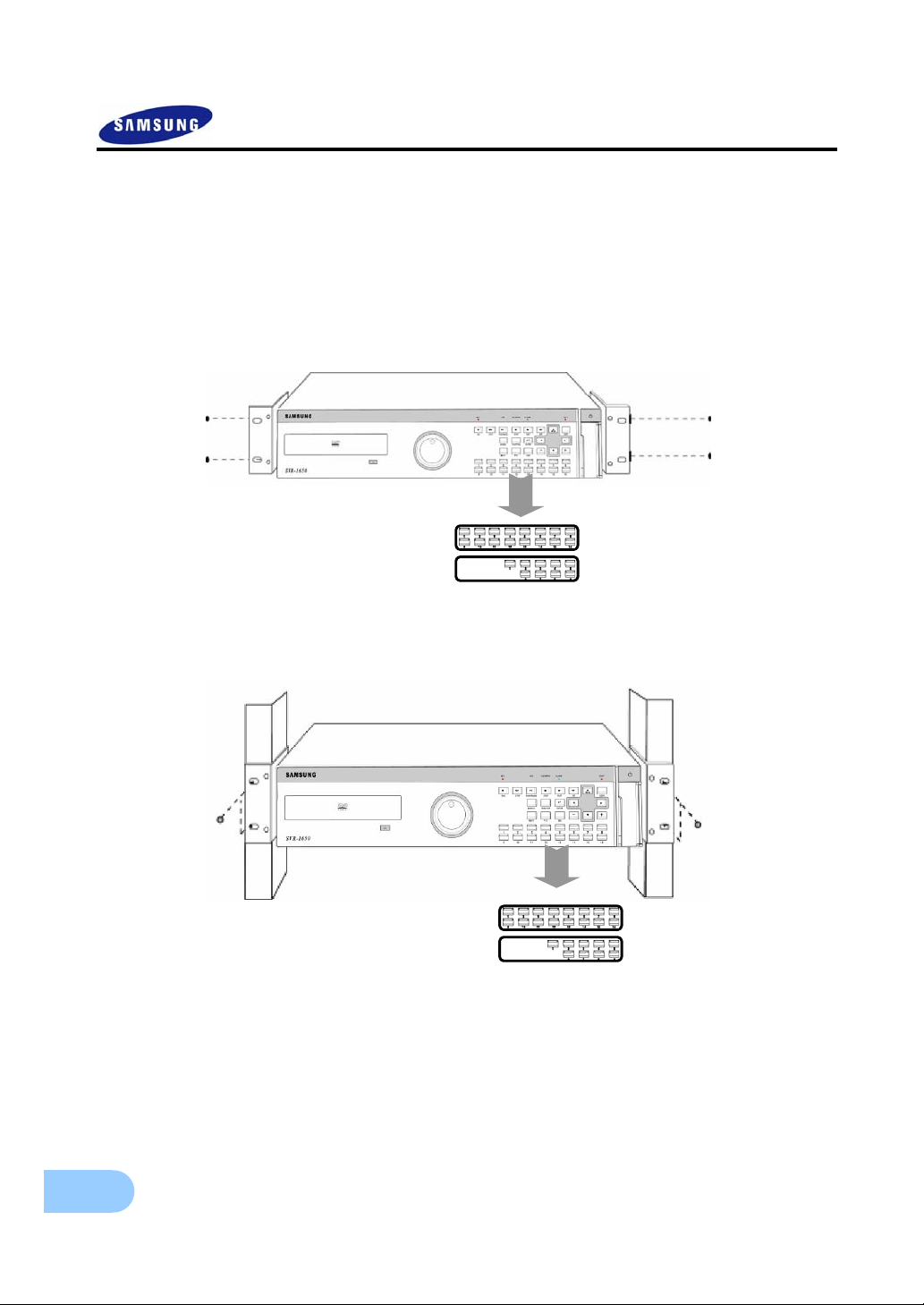
3.2.1 Rack mount
To mount the product, the enclosed rack must be mounted first. Mount sequence is as follows.
The enclosed rack mount is mounted on the product.
SVR-1650/1640
SVR-950
The product is mounted on the 19 inch rack.
SVR-1650/1640
SVR-950
22
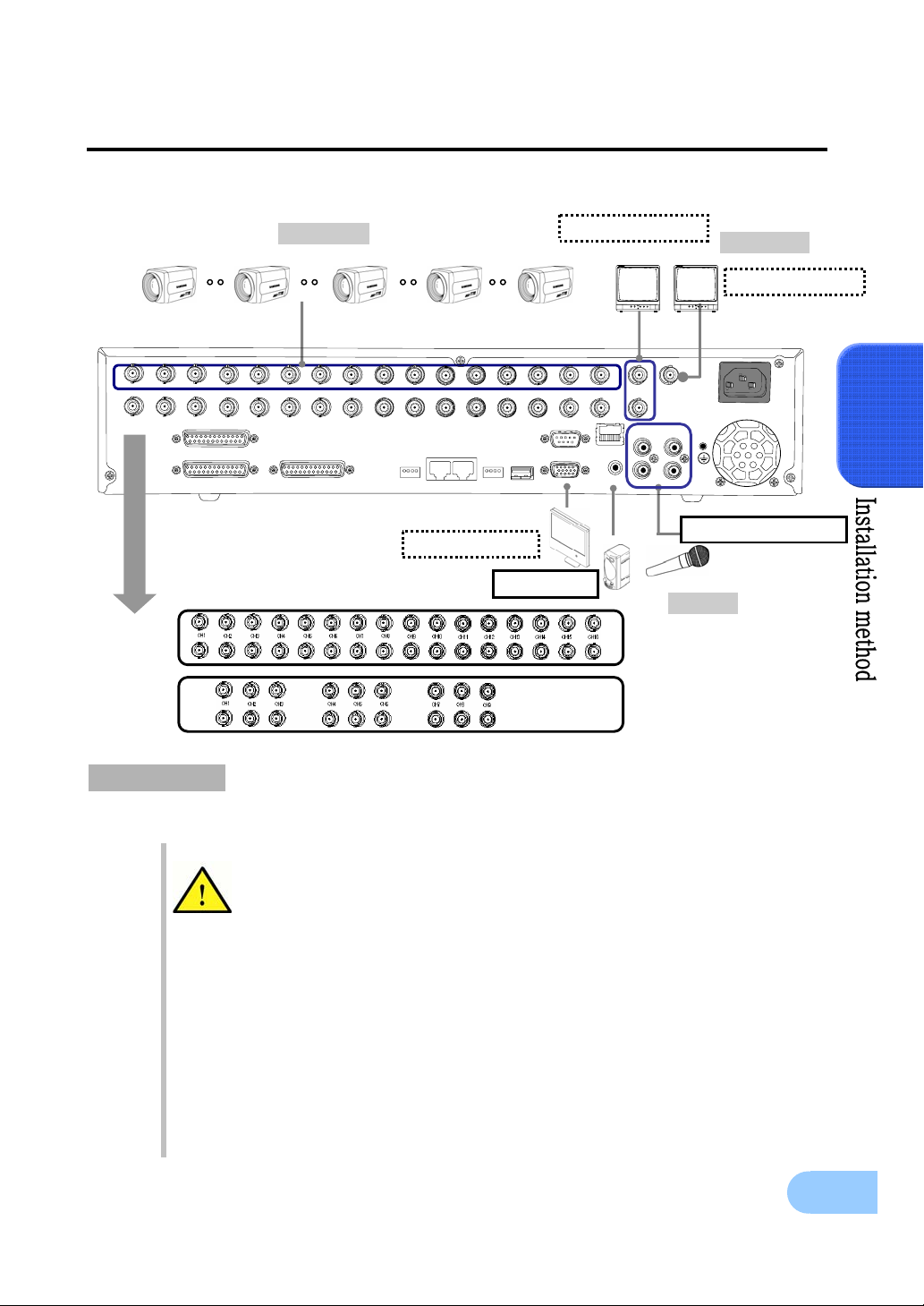
3.2.2 Video/Audio connection
SVR-1650/1640/950 User Manual
1
H
C
SVR-1650/1640
SVR-950
1. Camera
2
H
C
3
H
C
4
H
C
5
H
C
6
H
C
7
H
C
8
H
C
9
H
C
0
1
H
C
1
1
H
C
2
1
H
C
3
1
H
C
S
R
4
-
2
2
/
4
8
SENSOR IN
RELAY OUT
T
CONSOLE
5
M
R
1
E
M
R
2
E
T
S
U
1 2 3 41 2 3 4
Main Monitor
4
1
H
C
5
1
H
C
-23
S
C
2
R
,4
3
B
A
G
V
2. Monitor
Spot Mo
IT
M
N
O
A
O
1
R
M
B
O
R
IT
N
O
16
H
C
IT
M
N
O
A
O
2
R
2
IO
IN
D
U
1
A
IO
IN
D
U
A
T
E
N
R
E
H
T
E
IO
D
U
A
T
U
O
4
IO
IN
D
U
A
3
IO
IN
D
U
A
3
Audio(Line input)
VGA Monitor
Speaker
3. Voice
1. Camera
Up to 16(SVR-950: Up to 9) CCTV cameras can be connected to DVR.
Connect the BNC terminal for each camera to the CAMERA IN terminal in the back of this product.
If BNC terminal is only connected to CAMERA IN, a 75Ω terminating resistor is
setup internally.
If connected to both CAMERA IN and CAMERA OUT, the device receiving the
output must setup a termin ating resisto r of 75Ω.
Since CAMERA OUT terminal is a loop output for the camera input, it should only
be connected and used when there is an image input in CAMERA IN terminal.
If cable connected to the CAMERA OUT terminal is not connected to an external
device and is left exposed, image quality may be adversely affected.
Input video system type (NTSC/PAL) is recognized automatically when the
product power butto n is pushed. However, if a CCTV using a different system type
is connected to a CAMERA IN terminal during product operation, the product
must be turned OFF and ON again for proper automatic recognition of the input
video system type .
23

Image input from each camera is output simultaneously to the external device
connected to the MONITOR OUT terminal in the back of the product.
2. Monitor
To output screen information to the main monitor, connect the VGA terminal for monitor output in the
back of the product and the monitor BNC terminal with a BNC cable. There are 5 monitor output terminals
[BNC 3(SPOT 1), RCA 1, VGA 1) and up to 5 auxiliary monitors can be connected.
Monitor outputs are labeled A and B. If one monitor is used, it is connected to
MONITOR A. MONITOR B is used to connect the SPOT monitor.
3. Voice connection
This product has a function to store input voice information. Appropriate devices must be connected to
store or output voice information.
Voice input
Connect a RCA voice input terminal (like a line level input) to the AUDIO IN terminal in the back of the
product.
To setup voice input, set [AUDIO] to ON in the record setup screen in the Setup
Voice output
Connect a RCA voice output terminal (like a monitor with a speaker) to the AUDIO OUT terminal in the
back and front of the product.
menu. Refer to ‘5.7 Record setup’ for details.
Four voice inputs are each synchronized 1:1 with CH1~CH4 and voice output is
only possible in the single screen mode. Voice is not output even during single
mode double speed playback. Voice playback is not possible for live, playback and
network multi screen modes.
24
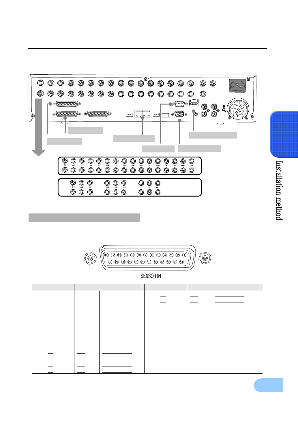
3.2.3 External connector
1
1
H
H
C
C
2
2
H
H
C
C
3
3
H
H
C
C
4
4
H
H
C
C
5
5
H
H
C
C
6
6
H
H
C
C
7
7
H
H
C
C
8
8
H
H
C
C
SENSOR IN
SENSOR IN
CONSOLE
RELAY OUT
RELAY OUT
CONSOLE
SVR-1650/1640/950 User Manual
M
M
O
O
IT
IT
N
N
O
O
A
A
1
1
R
R
IT
IT
M
M
N
N
O
O
B
B
O
O
R
R
9
9
H
H
C
C
0
0
1
1
H
H
C
C
1
1
1
1
H
H
C
C
2
2
1
1
H
H
C
C
3
3
1
1
H
H
C
C
4
4
1
1
H
H
C
C
5
5
1
1
H
H
C
C
6
6
1
1
H
H
C
C
M
M
A
A
O
O
2
2
R
R
IT
IT
N
N
O
O
2
2
IO
IO
IN
IN
D
D
U
U
1
1
A
A
IO
IO
IN
IN
D
D
U
U
A
A
S
S
R
R
4
4
-
-
2
2
2
2
/
/
4
4
8
8
5
T
M
M
R
R
2
2
E
E
T
T
1 2 3 41 2 3 4
1 2 3 41 2 3 4
5
M
M
R
R
1
1
E
E
T
-2
-2
S
S
R
R
,4
,4
3
3
B
B
S
S
U
U
V
V
T
T
E
E
N
N
R
R
E
E
H
H
T
T
E
E
C
C
32
32
IO
IO
D
D
U
U
A
A
A
A
G
G
O
O
T
T
U
U
4
4
IO
IO
IN
IN
D
D
U
U
3
3
A
A
IO
IO
IN
IN
D
D
U
U
A
A
2. Relay Out
1. Sensor In
3. RS-422/485
4. RS-232C
6. LAN(Ethernet)
5. VGA Monitor
SVR-1650/1640
SVR-950
1. Sensor input (SENSOR IN)
This is an external sensor connection terminal used to input information from the connected sensors or
devices to the product.
No. Description No. Description
1 S1 SENSOR 1 14 S14 SENSOR 14
2 S2 SENSOR 2 15 S15 SENSOR 15
3 S3 SENSOR 3 16 S16 SENSOR 16
4 S4 SENSOR 4 17 GND Ground
5 S5 SENSOR 5 18 GND Ground
6 S6 SENSOR 6 19 GND Ground
7 S7 SENSOR 7 20 GND Ground
GND
GND
GND
GND
GND
10
11
12
13
8
9
S8
S9
S10
S11
S12
S13
SENSOR 8
SENSOR 9
SENSOR 10
SENSOR 11
SENSOR 12
SENSOR 13
21
22
23
24
25
Ground
Ground
Ground
Ground
Ground
25
3
Sensor input type can be setup in the Event setup screen in the Main menu. Refer
to ‘5.8.1 Event setup’ for details.
※ For SVR-950, sensors 10 to 16 are not connected (NC)
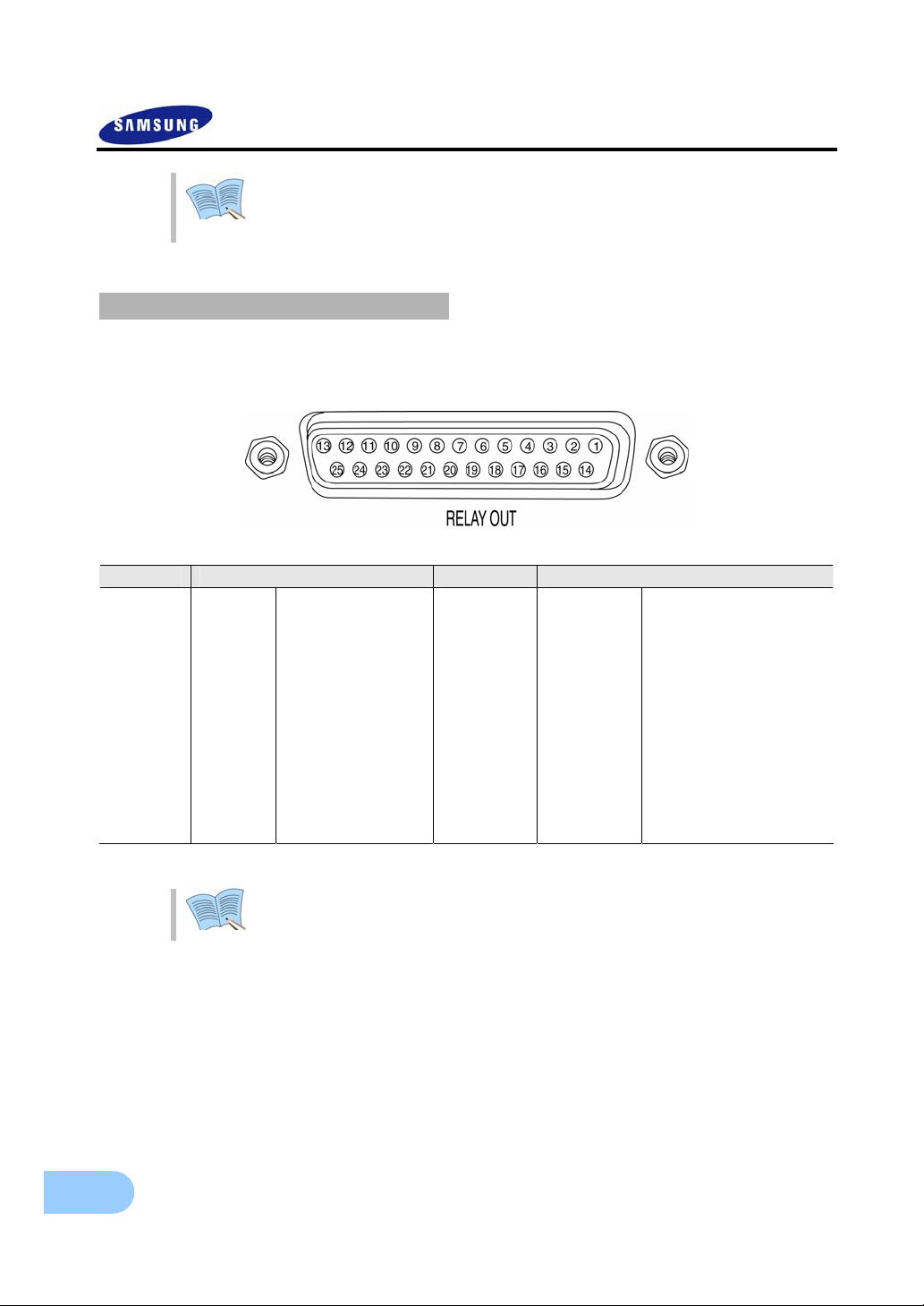
2. Relay output (RELAY OUT)
This is an alarm output terminal used to output alarms for sensor, motion detection, video loss and power
OFF to external devices.
No. Description No. Description
1 NO1 Normal Open 14 D_IO 0 Digital I/O
2 CM1 Common 15 D_IO 1 Digital I/O
3 NC1 Normal Close 16 D_IO 2 Digital I/O
4 NO2 Normal Open 17 D_IO 3 Digital I/O
5 CM2 Common 18 D_IO 4 Digital I/O
6 NC2 Normal Close 19 D_IO 5 Digital I/O
7 NO3 Normal Open 20 D_IO 6 Digital I/O
8
9
10
11
12
13
CM3
NC3
NO4
CM4
NC4
GND
Common
Normal Close
Normal Open
Common
Normal Close
Ground
21
22
23
24
25
D_IO 7
GND
GND
GND
GND
Digital I/O
Ground
Ground
Ground
Ground
For operation of each relay output, refer to the main menu event setup in ‘5.8.3
Relay setup’ .
26
SVR-1650/1640/950 User Manual
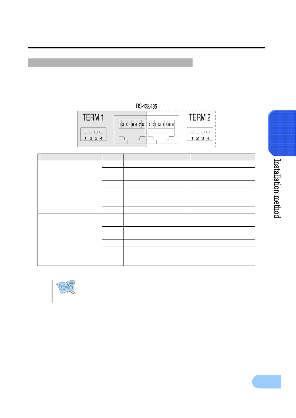
3. External control equipment (RS-422/485)
This is a terminal for connecting external control equipment.
The switch labeled TERM is used to turn ON/OFF terminating resistance for RS–422/485 communication
equipment.
PORT No. RS-422 RS-485
PORT A
(Controller
SCC-3100A Control)
PORT B
(Speed Dome Control)
1 RX+ (+Data Receive) Data+
2 RX- (-Data Receive) Data3 N/C (Not connected) N/C (Not connected)
4 N/C (Not connected) N/C (Not connected)
5 GND(Ground) GND(Ground)
6 N/C (Not connected) N/C (Not connected)
7 Tx-(-Data Send) Data8 Tx+(+Data Send) Data+
9 Rx+(+Data Receive) Data+
10 Rx-(-Data Receive) Data11 N/C (Not connected) N/C (Not connected)
12 N/C (Not connected) N/C (Not connected)
13 GND(Ground) GND(Ground)
14 N/C (Not connected) N/C (Not connected)
15 Tx-(-Data Send) Data16 Tx+(+Data Send) Data+
3
TERM 1 switch controls PORT A, TERM 2 Switch controls PORT B
1, 2 : ON → RS-485 MODE, OFF .→ RS-422 MODE
3, 4 : ON → Termination On, OFF → Termination Off
27
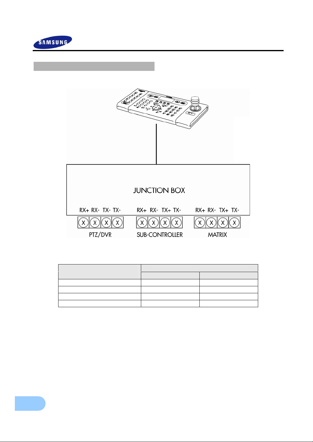
PORT A : SCC-3100A terminal
28
DVR PORT A Controller Terminal
( PORT 1)
RX+ 1 or 8 8
RX- 2 or 7 7
TX+ 1
TX- 2
※ RS-422/485 connection can be selected from the SW1 switch.
To connect RS-485: SW1 switch 1, 2 are turned ON.
To connect RS-422: SW1 switch 1, 2 are turned OFF
RS-485
RS-422
 Loading...