


Digital Video Recorder SVR-1670 User Guide
Beforeinstallingandoperatingthisproduct, pleasereadthismanualthoroughly.
ENGLISH
Digital Video Recorder 1 User Guide
Firmware Version 1.0.0

Product Warranty and Limits of Responsibility
Samsung does not assume any other responsibility concerning the sale of this product and does not delegate any right to a third party to take any responsibility on its behalf. Product warranty does not cover accident, negligence, alteration, misuse or abuse. In addition, no warranty is offered for any attachments or parts not supplied by the manufacturer.
The warranty period for this product is three (3) years from the date of purchase. The warranty period for HDD and Fan is one year after purchase.
The following are not covered by the warranty:
•Malfunction due to negligence or improper handling by user
•Deliberate disassembly and replacement by user
•Connection to an improper power supply
•Malfunction caused by natural disasters (fire, flood, etc.)
•Replacement of expendable parts (HDD,Fan,etc.)
•Replacement of expendable parts using ones from an unauthorized third party
Warranty only refers to the warranty covering products that have been purchased. During the warranty period, repair and examination of items outside the warranty scope will be provided for a fee. After the warranty period expires,examination and repair of the product will be provided for a fee.
Thisproductisnotintendedtobetheprimarymeansforpreventingfireandtheft.Thecompanyisnot responsible for any accidents or damage that may occur as a result of using this product.
Prior experience and technical expertise is required to install the product. Installing the product without proper knowledge can cause fire, electric shock, or other damage. Installation should be performed by the agency from which you purchased the product.
Samsung may implement, without prior notice, firmware or software upgrades or changes to the appearance of the product.
Copying and reprinting this manual, either partially or in its entirety, or translating it into another language without the consent of Samsung Techwin, Inc. is prohibited. Copying for general use is acceptable if within copyright law.
Table of contents
ProductWarranty and Limits of Responsibility … ………………………………… 2 Table of contents ………………………………………………………………… 3
Chapter 1.About Safety,Compliance and Disposal……………………………… 5
1. 1 Warnings… ……………………………………………………………… 5
1. 2 Cautions… ……………………………………………………………… |
6 |
1. 3 Compliance Statements…………………………………………………… |
6 |
1.4 Disposal Procedures… …………………………………………………… 7
Chapter 2. SVR-1670 Description ………………………………………………… 7
2.1 About the SVR… ………………………………………………………… 8
2.2 Features… ……………………………………………………………… 8
2.3 Package Contents………………………………………………………… 10
2.4 Front Panel Overview……………………………………………………… 11
2.5 Rear Panel Overview……………………………………………………… 13
2. 6 The Remote Control… …………………………………………………… 14
Chapter 3. Hardware Installation… …………………………………………… 17
3.1 Installing the SVR-1670 in a Rack… ……………………………………… 18
3.2 Working with Input/Output Terminals… …………………………………… 18
3.3 Basic Connections to the SVR-1670… …………………………………… 19
3.4 Extended Connections to the SVR-1670… ………………………………… 25
3.5 Remote Monitoring and Control… ………………………………………… 31
3.6 Hard Disk Drive Installation……………………………………………… 32
Chapter 4. Navigation:On-Screen Display and Function Menus………………… 38
4. 1 Working with the On-Screen Display… …………………………………… 38
4.2 Working with the Function Key Menu… …………………………………… 42
Chapter 5. Quick Setup………………………………………………………… 44
5.1. Working on the Quick Setup Menu………………………………………… 44
5.2. Setting the Record Mode… ……………………………………………… 45
5.3. Setting the Date and Time………………………………………………… 46
Chapter 6. Using the System Setup Menu… …………………………………… 47
6. 1 Using the System Setup Options…………………………………………… 47 6. 2 Using the Disk Options on the System Setup Menu… ……………………… 50 6. 3 Working with Passwords and Permissions… ……………………………… 52
Chapter 7. CommunicationTo / From the DVR… ……………………………… 55
7. 1. Setting up Network Communication… …………………………………… 55
7. 2. Registering with a DDNS Server………………………………………… 58
7. 3. Setting up for NTP Synchronization… …………………………………… 62
7. 4. Setting up Remote Control Devices… …………………………………… 63
7. 5 Setting Up Streaming Options……………………………………………… 65
7. 6 Setting Up IP Filters… …………………………………………………… 65
Digital Video Recorder 2 User Guide |
Digital Video Recorder 3 User Guide |
Table of contents
Chapter 8.Working with Events……………………………………………… 66
8. 1 About Events……………………………………………………………… 66
8. 2 Setting Up for Event Recording… ………………………………………… 66
8. 3 Working with Normal Events… …………………………………………… 69
8. 4 Working with Presets……………………………………………………… 72
8. 5 Working with Digital I/O…………………………………………………… 72
8. 6 Defining Programs………………………………………………………… 74
8. 7 Setting Up To Record……………………………………………………… 76
Chapter 9. Camera and Monitor Display Setup… ……………………………… 80
9. 1 Setting Up the Camera Display… ………………………………………… 80
9. 2 About Multichannel Screen Display………………………………………… 81
9. 3 Setting Up the Monitor Display… ………………………………………… 82
9. 4 Using Auto Sequencing… ………………………………………………… 83
9. 5 Configuring Multi Display Layouts… ……………………………………… 84
Chapter 10. Camera Commandss… …………………………………………… 85
10. 1 Camera Commands from the FUNC Key Menu… ………………………… 85 10. 2 Pan/Tilt/Zoom Commands… …………………………………………… 85
Chapter 11.Working with RecordedVideo……………………………………… 88
11. 1 Various Playback Options………………………………………………… 88
11. 2 Searching for Recorded Video… ………………………………………… 89
11. 3 About Copying Video… ………………………………………………… 92
Chapter 12. UsingWebViewer… ……………………………………………… 94
12. 1 System Requirements… ………………………………………………… 94
12. 2 Starting Web Viewer…………………………………………………… 94
12. 3 Monitoring… …………………………………………………………… 95
12. 4 Playback………………………………………………………………… 98
AppendixA. Specifications of the SVR-1670… ………………………………… 100 Appendix B. Recording Program Default Settings … …………………………… 102 Appendix C. Supported PTZ Controllers and Protocols… ……………………… 104 Appendix D. Factory Default Settings………………………………………… 106 Appendix E. Glossary………………………………………………………… 116 Dimension… ………………………………………………………………… 121 Memo … …………………………………………………………………… 122
Chapter 1. About Safety, Compliance and Disposal
This chapter explains important information about safe use of the SVR-1670, its compliance to FCC and ECO RoHS regulation,and how to properly dispose of the equipment.
The information is presented in these sections:
•1. 1Warnings
•1. 2 Cautions
•1. 3 Compliance Statements
•1. 4 Disposal Procedures
1. 1 Warnings
SamsungTechwin,although not responsible for accidents or damage that might occur as a result of using this SVR1670, wants you to use it wisely and safely. In this section, we provide several warnings you should follow before installing the equipment,during operation, and if dismantling or cleaning the equipment.
Heed these warnings to prevent serious injury, shock or death.
•Before installation
To avoid fire, explosion,malfunction or electric shock,observe these practices:
-Disconnect the power supply before installation.
-Verify that you can install to correct voltage(AC100V~AC240V) before connecting to power supply.
-Never install in a very humid environment.
-Properly ground the SVR-1670 as well as any equipment you are connecting to it.
•During operation
To avoid fire, explosion,malfunction or electric shock,observe these practices:
-If the SVR-1670 cover ever needs to be opened, rely on qualified personnel or system installers, who know how to do safely.
-Never plug multiple appliances into a single power outlet.
-Never place heavy objects or dishes holding water on product.
-Never use the SVR-1670 where excessive dust or flammable substances such as propane gas are present.
-Never touch power line with wet hand.
-Never insert hand into the DVD dock.
-Never put conductive materials into the cooling ventilator opening.
-Never apply excessive force when pulling on power cord.
-Replace built-in battery with same battery type. Dispose of old batteries properly
-Never place battery near fire or extreme heat.
-Never dissect or disassemble battery.
•Dismantling and Cleaning
-Use a dry cloth to clean the exterior.
-Never use water,paint thinner or organic solvent to clean the product exterior.
-Never deliberately dismantle,repair or modify product.
Digital Video Recorder 4 User Guide |
Digital Video Recorder 5 User Guide |

Chapter 1. About Safety, Compliance and Disposal
1. 2 Cautions
Samsung Techwin, although not responsible for accidents or damage that might occur as a result of using this product, wants you to use it wisely and safely. In this section, we provide several cautions you need to follow before installing or operating the equipment.
Heed these cautions to prevent minor injury to users or damage to the equipment. You will see other cautions throughout this manual. Cautions are indicated by the exclamation point symbol.
•During Installation
Prevent accidents and avoid injury or malfunction, observe these practices :
-For adequate ventilation, install the SVR-1670 with at least 6 in (15cm) of space between cooler fan and wall surface.
-Install on a flat surface.
-Never install in areas exposed to direct sunlight or excessive heat.
-Connect a camera to the SVR-1670 before recording and storing images. (If a camera is installed while SVR-1670 is recording, the image in another channel might be disrupted.)
•During Use
-Never expose the SVR-1670 to shocks or shaking during use.
-Never move, throw or expose to excessive physical shock during use.
-Installing unapproved hard disk drives can result in abnormal operation. Use only approved products. The SVR-1670’s product warranty does not cover malfunction due to installation of unapproved hard disk drives.
-Samsung Techwin recommends the installation of a UPS (Uninterrupted Power Supply) with all its recording products.
1. 3 Compliance Statements
•FCC Compliance Statement
This equipment has been tested and found to comply with the limits for a ClassA digital device,pursuant to part 15 of the FCC Rules. These limits are designed to provide reasonable protection against harmful interference when the equipment is operated in a commercial environment.This equipment generates,uses,and can radiate radio frequency energy and, if not installed and used in accordance with the instruction manual, might cause harmfulinterferencetoradiocommunications.Operationofthisequipmentinaresidentialareaislikelytocause harmful interference in which case the user will be required to correct the interference at his expense.
•ECO RoHS Compliance
Samsung Techwin cares for the environment and strives to preserve it during all product manufacturing stages and to provide customers with environment-friendly products. The Eco mark represents Samsung Techwin’s goal to create environmentfriendly products and indicates that the product satisfies the EU RoHS Directive.
1. 4 Disposal Procedures
The following procedures are applicable in the European Union and other European countries to comply with correct disposal of waste electrical and electronic equipment,and batteries.
• Correct Disposal of Waste Electrical and Electronic Equipment
This marking, shown on the product or its literature, indicates that it should not be disposed of with other household wastes at the end of its working life. To prevent possible harm to the environment or human health from uncontrolled waste disposal, please separate this from other types of wastes and recycle it responsibly. Household
users should contact either the retailer where they purchased this product, or their local government office, for details of where and how they can take this item for environmentally-safe recycling. Business users should contact their supplier and check the terms and conditions of the purchase contract.This product should not be mixed with other commercial wastes for disposal.
• Correct Disposal of Batteries
This marking on the battery, manual or packaging indicates that the batteries in this product should not be disposed of with other household waste at the end of their working life. Where marked, the chemical symbols Hg, Cd or Pb indicate that the battery contains mercury, cadmium or lead above the reference levels in EC Directive
2006/66. If batteries are not properly disposed of, these substances can cause harm to human health or the environment. To protect natural resources and to promote material reuse, please separate batteries from other types of waste and recycle them through your local, free battery return system. The rechargeable battery incorporated in this product is not user-replaceable. For information on its replacement, please contact your service provider.
Chapter 2. SVR-1670 Description
This chapter provides information about the Samsung SVR series SVR-1670 (digital video recorder) and contains a description of SVR parts and accessories.
The information is presented in these sections:
•2. 1About the SVR-1670
•2. 2 Features
•2. 3 Package Contents
•2. 4 Front Panel Overview
•2. 5 Rear Panel Overview
•2. 6The Remote Control
Digital Video Recorder 6 User Guide |
Digital Video Recorder 7 User Guide |

Chapter 2. SVR-1670 Description
2. 1 About the SVR
The SVR-1670 in the Samsung SVR series records and plays video from up to 16 channels. In addition, the SVR can alert you of the occurrence of user-defined events, such as motion detection, using the buzzer,on the screen,or via e-mail.Various methods are provided to configure and control this product: the front panel control board, mouse, remote controller, Web Viewer, SVM-S1 (CMS: Centralized Management Software),and controller.
Recorded high-quality video files are saved in the hard disk drive for search and play purposes.You can record,play,and copy video files from multiple channels in real time.This SVR provides a variety of advanced options: motion detection, PTZ controls (Pan/Tilt/Zoom), user permission settings and access control,real-time audio recording,event logging and search.
2. 2 Features
The various features of the SVR-1670 are discussed below and include:
•Monitoring Screen
•Video Recording
•Audio Recording
•Search and Playback
•Data Storage
•Networking
•Additional Features
•Monitoring Screen
The monitoring screen provides vivid, high-definition live video feeds from all 16 channels. On the split-screen, you can view 4,9,10,or 16 channels as well as single-channel display.To facilitate viewing,an auto-sequencing feature automatically switches to each connected channel after a set interval.
- To the SVR-1670, two composite monitors and a single VGA monitor can be connected.
•Video Recording
The SVR-1670 stores video image data as high-resolution H.264 files at a maximum rate of 480 frames per second. When recording video based on events, pre-event video of up to five seconds is also recorded. With an advanced“covert”feature,the SVR-1670 protects the public’s privacy by identifying certain areas in the field of view that are concealed during recording.
To effectively manage the data storage capacity of the SVR, you can adjust its recording performance using software that defines the resolution, frame rate,and recording quality.
Motion detection settings, recording rates and recording modes can be programmed for each channel individually.
The SVR-1670 provides several recording functions to accommodate any combination of manual and scheduled recording.Along with multiple recording modes,users can perform all of the following functions simultaneously: view recorded video, record video, backup video to the hard disk or external storage media, and monitor and perform other networking operations.
An event log stores information on all event sensor activity,digital input/output activity,video loss detection,and text-based transactions.
•Audio Recording
The SVR-1670 supports real-time audio input and recording for 16 channels simultaneously. Four RCA channels and 12 D-SUB Channels are provided on the rear panel along with one audio output channel for use with a microphone.Audio can be recorded and played back simultaneously.
•Search and Playback
Search and playback options on the SVR-1670 include support for playback based on time, date and channel, a graphical interface to input data search criteria, forward and backward search of paused video, playback logs for all events, full frame playback, and access to search functions from the remote control or the front panel
JOG/SHUTTLE.
•Data Storage
A hard disk is included with the product for data storage.The recorded data also can be stored to external media such as a DVD+R,DVD-R,CD-R or USB.
When used in conjunction with external storage,the SVS-5R can save up to 32TB of data.
•Networking
The SVR-1670 supports LAN, RTSP protocol and xDSL networking capabilities across a 10/100/1000 Mpbs Ethernet connection.SeveralSVR-1670scanbeconnectedacrossanetwork.CombinedwiththePCinterfaceclient,thecorefeatures of the device can easily be controlled remotely.A network connection is required for the following features:
-E-mail notification of events,which can be sent viaTCP/IP or DHCP
-Remote monitoring of live video
-RunningtheSVM-S1 to search forandplayback recordedvideo,managestorage devices,setup recordingschedules,and control the SVR-1670 remotely
•Additional Features
The following features are also available on the SVR-1670 :
-18-language OSD: Korean, English, Japanese, Chinese, Taiwanese, Spanish, French, Italian, German, Portuguese, Polish, Turkish,Russian,Swedish,Danish,Serbian,Rumanian,and Czech)
-Easy firmware upgrade via USB or over the network.
-PTZ control and Preset function
Digital Video Recorder 8 User Guide |
Digital Video Recorder 9 User Guide |

Chapter 2. SVR-1670 Description
2. 3 Package Contents
Refer to the package contents diagram to ensure that all accessories are provided with your SVR1670.
Figure 2.3.1 Package Contents – SVR-1670 and Mouse
AC CORD |
Remote controller |
Program CD |
|
|
|
SATA Cable |
HDD Mount Screw |
SVR-1670 Quick Guide / SVR-1670 |
|
User's Guide |
|||
|
|
Quick Guide |
Rack Mount |
Mouse |
Figure 2.3.2 Package Contents Diagram
2. 4 Front Panel Overview
The front panel of the SVR-1670 has the following controls and indicators:
|
|
Figure 2.4.1 SVR-1670 Front Panel |
|
|
|
|
|
No. |
Name |
|
Function |
|
|
|
|
1 |
DVD-Multi drive |
|
Copies recorded video and images to DVD or CD-ROM |
|
optical media. |
||
|
|
|
|
|
|
|
|
2 |
Channel LED |
|
Shows data input and event operation status for each |
|
attached camera. |
||
|
|
|
|
|
|
|
|
|
|
|
Use the jog dial to search recorded video precisely per |
3 |
JOG/SHUTTLE |
|
frame. |
|
The shuttle can be used to change the play speed while |
||
|
|
|
|
|
|
|
playing or searching video, forward or backward. |
|
|
|
|
|
REC light |
|
Lit when the unit is recording. |
|
|
|
|
|
HDD light |
|
Lit when the hard disk is active. |
|
|
|
|
4 |
NETWORK light |
|
Lit during network activity. |
|
|
|
|
EVENT light |
|
Lit to indicate event detection. |
|
|
|
||
|
|
|
|
|
COPY light |
|
Lit when copying. |
|
|
|
|
|
PLAY light |
|
Lit during copying of live video. |
|
|
|
|
5 |
Power button |
|
Turns SVR-1670 on or off. |
|
|
|
|
6 |
REC button |
|
Starts or stops manual recording. |
|
|
|
|
7 |
Channel button |
|
Selects the channel to view live or playback video. |
|
|
|
|
8 |
MULTI |
|
Changes split-screen sections for live video feeds or |
|
playback. |
||
|
|
|
|
|
|
|
|
Digital Video Recorder 10 User Guide |
Digital Video Recorder 11 User Guide |

Chapter 2. SVR-1670 Description
9 |
AUTO |
Starts or stops user-defined sequences. |
|
|
|
|
|
10 |
PTZ |
Starts or stops a PTZ function. |
|
|
|
|
|
11 |
MONITOR |
Switches between the main and spot monitors. |
|
|
|
|
|
12 |
MENU |
Opens the on-screen display menu. |
|
|
|
|
|
13 |
SEARCH |
Starts Search mode. |
|
|
|
|
|
14 |
COPY |
Starts Copy mode. |
|
|
|
|
|
15 |
FUNC |
Starts Function mode. |
|
|
|
|
|
16 |
ESC |
Each time pressed, closes open submenus and menus. |
|
|
|
|
|
17 |
PLAY/ENTER |
Starts playback or selects an item on the menu. |
|
|
|
|
|
18 |
/REW |
Goes to or selects in the menu. For playback, changes the |
|
reverse playback speed. |
|||
|
|
||
|
|
|
|
19 |
/FFW |
Goes to or selects in the menu. For playback, changes the |
|
forward playback speed. |
|||
|
|
||
|
|
|
|
20 |
▲/PAUSE |
Goes to or selects in the menu. For playback, pauses live or |
|
recorded video. |
|||
|
|
||
|
|
|
|
21 |
▼/STOP |
Goes to or selects in the menu. For playback, stops playback. |
|
|
|
|
|
22 |
USB1, USB2 |
USB ports for external devices (mouse, USB memory stick). |
|
|
|
|
2. 5 Rear Panel Overview
The rear panel of the SVR-1670 has the following connections:
Figure 2.5.1 SVR-1670 Rear Panel
No. |
Terminal Name |
Function |
|
|
|
|
|
1 |
Power Input |
Socket for AC 100V ~ AC 240V power cord |
|
|
|
|
|
2 |
Ch1 ~ 16 |
Connection terminal for camera BNC input |
|
|
|
|
|
3 |
Loop Out |
Connection terminal for camera BNC output (loop) |
|
|
|
|
|
4 |
Monitor 1~2 |
Connection terminal for monitor BNC output |
|
|
|
|
|
5 |
Audio In (RCA) |
RCA audio jack for RCA input |
|
|
|
|
|
6 |
Audio Out |
Audio jack for speaker output |
|
|
|
|
|
7 |
Ground |
A terminal that is used to ground SVR-1670 main frame. |
|
|
|
|
|
8 |
eSATA |
A terminal for an external eSATA backup device. |
|
|
|
|
|
9 |
VGA Output |
Output port for PC monitor |
|
|
|
|
|
10 |
Serial Port |
RS-232C D-SUB connector |
|
|
|
|
|
|
Serial Port |
Connection terminal for expanded control, speed dome |
|
11 |
(Terminal Block) |
||
camera, and other such equipment. |
|||
|
(RS-232C/485/422) |
||
|
|
||
|
|
|
|
12 |
Sensor In |
Connection terminal for sensor input |
|
|
|
|
|
13 |
Relay Out |
Connection terminal for relay output |
|
|
|
|
|
14 |
Audio In (D-SUB) |
Connection terminal for audio output D-SUB |
|
|
|
|
|
15 |
D-I/O |
Connection terminal for Digital In/Out |
|
|
|
|
|
16 |
Ethernet |
Ethernet port for network connections (RJ-45) |
|
|
|
|
Digital Video Recorder 12 User Guide |
Digital Video Recorder 13 User Guide |

Chapter 2. SVR-1670 Description
2. 6 The Remote Control |
No. |
|
|
|
|
|
Name |
|
Function |
|||
You can control all SVR-1670 features using the remote control device.You can also control multiple |
|
|
|
|
|
|
|
|
|
|
||
1 |
ID |
|
|
Selects the unique ID. |
||||||||
SVR-1670s from one remote control device.This section explains how in these topics : |
|
|
|
|
|
|
|
|
|
|
||
2 |
FUNC |
|
|
Starts Function mode. |
||||||||
|
• Buttons on the Remote Control. |
|
|
|||||||||
|
|
|
|
|
|
|
|
|
|
|
||
|
|
|
|
|
|
|
|
|
|
|
||
|
• Setting Unit SVR-1670 IDs. |
3 |
Channel buttons |
|
Changes channels. |
|||||||
|
• Usable Range of Remote Control. |
|
|
|
|
|
|
|
|
|
|
|
|
4 |
MENU |
|
|
Switches to the on-screen display menu. |
|||||||
|
• Changing Batteries. |
|
|
|||||||||
|
|
|
5 |
+10 |
|
|
|
|
|
|
|
Use this button to select a channel number from 10 to 16; |
|
|
|
|
|
|
|
|
|
|
for Channel 16, press +10 and then 6. |
||
|
|
|
|
|
|
|
|
|
|
|
|
|
|
Buttons on the Remote Control |
|
|
|
|
|
|
|
|
|
|
|
|
|
6 |
FAST REWIND ( |
) |
Fast reverses playback. |
|||||||
|
|
|
||||||||||
|
|
|
|
|
|
|
|
|
|
|
|
|
|
|
|
7 |
PAUSE ( |
|
|
|
|
) |
|
Pauses playback. |
|
|
|
|
|
|
|
|
||||||
|
|
|
|
|
|
|
|
|
|
|
|
|
|
|
|
8 |
FORWARD PLAY ( |
) |
Forwards playback. |
||||||
|
|
|
|
|
|
|
|
|
|
|
|
|
|
|
|
9 |
FAST FORWARD ( |
) |
Fast forwards playback. |
||||||
|
|
|
|
|
|
|
|
|
|
|
|
|
|
|
|
10 |
RECORD ( |
) |
|
Starts and stops manual recording. |
|||||
|
|
|
|
|
|
|
|
|
|
|
|
|
|
|
|
11 |
STOP ( |
|
|
) |
|
Stops playback. |
|||
|
|
|
|
|
||||||||
|
|
|
|
|
|
|
|
|
|
|
|
|
|
|
|
12 |
|
|
|
|
|
|
|
|
Moves cursor up in the OSD menu. |
|
|
|
|
|
|
|
|
|
|
|
|
|
|
|
|
13 |
|
|
|
|
|
|
|
|
Moves cursor left in the OSD menus. |
|
|
|
|
|
|
|
|
|
|
|
|
|
|
|
|
14 |
(Enter) |
|
|
Saves settings and executes a function. |
|||||
|
|
|
|
|
|
|
|
|
|
|
|
|
|
|
|
15 |
|
|
|
|
|
|
|
|
Moves cursor right in the OSD menus. |
|
|
|
|
|
|
|
|
|
|
|
|
|
|
|
|
16 |
|
|
|
|
|
|
|
|
Moves cursor down in the OSD menus. |
|
|
|
|
|
|
|
|
|
|
|
|
|
|
|
|
17 |
ESC |
|
|
Cancels settings or goes up in the menu. |
|||||
|
|
|
|
|
|
|
|
|
|
|
|
|
|
|
|
18 |
AUTO |
|
|
Switches to automatic display mode. |
|||||
|
|
|
|
|
|
|
|
|
|
|
|
|
|
|
|
19 |
STATUS |
|
|
Displays system setup information. |
|||||
|
|
|
|
|
|
|
|
|
|
|
|
|
|
|
|
20 |
PTZ |
|
|
Switches to PTZ mode. |
|||||
|
|
|
|
|
|
|
|
|
|
|
|
|
|
|
|
21 |
MULTI |
|
|
Changes split-screen sections for live video or playback. |
|||||
|
|
|
|
|
|
|
|
|
|
|
|
|
|
|
|
22 |
COPY |
|
|
Displays the Copy menu and saves recorded video to an |
|||||
|
|
|
|
|
external storage device (USB). |
|||||||
|
|
|
|
|
|
|
|
|
|
|
|
|
|
|
|
|
|
|
|
|
|
|
|
|
|
|
|
|
23 |
MON |
|
|
Changes screen to spot monitor. |
|||||
|
|
|
|
|
|
|
|
|
|
|
|
|
|
|
|
24 |
SEARCH |
|
|
Displays the Search menu. |
|||||
|
|
|
|
|
|
|
|
|
|
|
|
|
|
Figure 2.6.1 Remote Control |
25~30 |
F1~F6 |
|
|
Reserved for future use. |
||||||
|
|
|
|
|
|
|
|
|
|
|
||
|
|
|
|
|
|
|
|
|
|
|
||
Digital Video Recorder 14 User Guide |
Digital Video Recorder 15 User Guide |

Chapter 2. SVR-1670 Description
Setting the SVR-1670’s ID for the Remote Control
You can control up to 16 SVR-1670s from one remote control by creating unique IDs for each SVR-1670.
· Setting the ID for the remote control device
Figure 2.6.2 Remote Control ID
1.From the OSD, select the Network menu.
2.Select the Remote submenu.
3.For the Remote Controller ID option, select an ID value. This will become the ID for the remote device you plan to use.
·Setting the ID for the remote control device
To select a specific SVR-1670, press the ID button on the remote controller repeatedly until you hear a buzzer for 2 seconds. After the buzzer, the SVR-1670 starts responding to the remote controller’s commands.
Usable Range of Remote Control
Figure 2.6.3 shows an angle when the remote controller is pointed to the DVR remote controller receiver.
Figure 2.6.3 Remote Control Device’s Usable Range
Changing Batteries
The Remote Control takes AAA-sized batteries. Here is how to insert new or replacement batteries:
1. To remove the rear battery cover, press it forward.
2. Check the battery contacts inside the remote controller: + and –. Insert each battery matching the battery contacts and battery poles.
3. Reinsert the battery cover.
Chapter 3. Hardware Installation
This chapter describes how to install the hardware. It includes instructions for installing the SVR-1670 in a rack or on a desktop; connecting devices to the SVR-1670 including cameras, monitors, sensors, and relays; and handling and preparing wiring.
The information is presented in these sections.
•3. 1 Installing the SVR-1670 in a Rack
•3. 2Working with Input/OutputTerminals
•3. 3 Basic Connections to the SVR-1670
•3. 4 Extended Connections to the SVR-1670
•3. 5 Remote Monitoring and Control
•3. 6 Hard Disk Drive Installation
Digital Video Recorder 16 User Guide |
Digital Video Recorder 17 User Guide |
Chapter 3. Hardware Installation
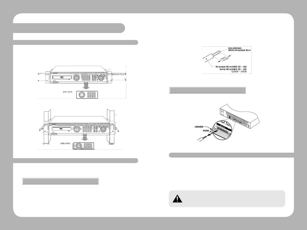
3. 1 Installing the SVR-1670 in a Rack
To use the SVR-1670 safely,please install the SVR in a rack using the enclosed rack mounts. Follow these instructions to install the SVR-1670 in a rack.
1. Attach the enclosed rack mounts to the product.
Rack Mount
2. Attach the enclosed rack mounts to the product.
Rack
Rack Mount
3. 2 Working with Input/Output Terminals
This section discusses the proper handling of wires and cables when connecting sensors, relays and other devices to the SVR-1670.
Handling Cable Ends
You might need to prepare cables before connecting them to terminal blocks. Different wire gauges are needed for stranded wire or solid wire. Prepare the end of the wire by removing the following amounts of insulation:
· Stranded wire : Strip 1/3 ~ 1/2" (8 ~ 10mm) of insulation off the end of the wire and solder it together. Use AWG 22 ~ 26 wire.
· Solid wire : Strip 1/3 ~ 1/2" (8 ~ 10mm) of insulation off the end of the wire. Use AWG 20 ~ 26.
Figure 3.2.1 Preparing Cables for Terminal Blocks
Wire Insertion and Removal
When inserting or removing a wire from a terminal block, do it while holding down the terminal block with a screw driver.
Figure 3.2.2 Inserting and Removing Wires
3. 3 Basic Connections to the SVR-1670
This section explains how to connect devices to the SVR-1670, within the following subsections:
•Basic Connection Diagram
•Connecting Cameras
•Connecting a Monitor
•ConnectingAudio
•Connecting the Power Cable
Always turn off the SVR-1670 and disconnect the power cord from its power source before you connect devices to the SVR-1670.
Digital Video Recorder 18 User Guide |
Digital Video Recorder 19 User Guide |
Chapter 3. Hardware Installation
Basic Connection Diagram
The following configuration diagram depicts a basic sample configuration that include cameras, monitors, sensors, and relays. These diagrams are representative only and are not intended to depict the only possible configurations for the SVR-1670.
Figure 3.3.1 Sample Connection Diagrams
Connecting Cameras
1.Ensure that the SVR-1670 is not connected to a live power source.
2.Using video cable, connect up to 16 standard CCTV cameras to the SVR-1670. Follow the instructions provided with the cameras to connect them to an external power source.
Figure 3.3.2 Connecting Cameras to the SVR-1670
Never connect both NTSC and PAL cameras to the SVR-1670 at the same time. The SVR1670 recognizes only one camera type at a time.
The following default settings are assigned to cameras that are connected to the SVR-1670.
·Video input type, which is determined by the device that is connected to the lowest channel number. For example, if there are five cameras connected to the SVR-1670 and the lowest channel number in use is 6, then the SVR-1670 will set the video input type to match the camera connected to channel 6.
·Terminal resistance, which the SVR-1670 automatically sets at 75Ω when one video input port is in use. When a lower video input port is also connected, the SVR-1670 automatically separates the terminal resistance between 75Ω and Hi-Z (high impedance).
About Video In and Out Connections
The SVR-1670 video input/output connections are “Loop through." Their connection status is detected automatically to set terminal resistance.
For example, when only video input is connected, terminal resistance is set internally to 75Ω. When video input and output are connected, terminal resistance is set to Hi-Z. This setting for input and output connections sets the external output device to 75Ω for terminal resistance.
Figure 3.3.3 Video Input and Output Connections
Digital Video Recorder 20 User Guide |
Digital Video Recorder 21 User Guide |

Chapter 3. Hardware Installation
|
3. Refer to Figure 3.3.6 when connecting devices with D-SUB cables. |
|
Connecting a Monitor |
||
|
1.Ensure that the SVR-1670 is not connected to a live power source.
2.Using a monitor cable,connect a monitor or monitors to the SVR-1670.
Figure 3.3.4 Connecting Monitors to the SVR-1670
3. Connect the monitor’s power cord to the monitor and to an external power source.
Connecting Audio
1.Ensure that the SVR-1670 is not connected to a live power source.
2.Using RCA audio cables or D-SUB cables,attach a microphone and speakers to the SVR-1670.
Figure 3.3.5 Connecting Audio to the SVR-1670
Figure 3.3.6 The Audio Pin Assignments
Audio In/Out Connections
There are four RCA audio in and 12 D-SUB audio in connections. All 16 audio sources can be monitored through a single output. The 12 D-SUB audio inputs use terminals 2 through 15 and are connected as shown in Figure 3.3.7.
Figure 3.3.7 Audio Input and Output Connections
Digital Video Recorder 22 User Guide |
Digital Video Recorder 23 User Guide |
Chapter 3. Hardware Installation
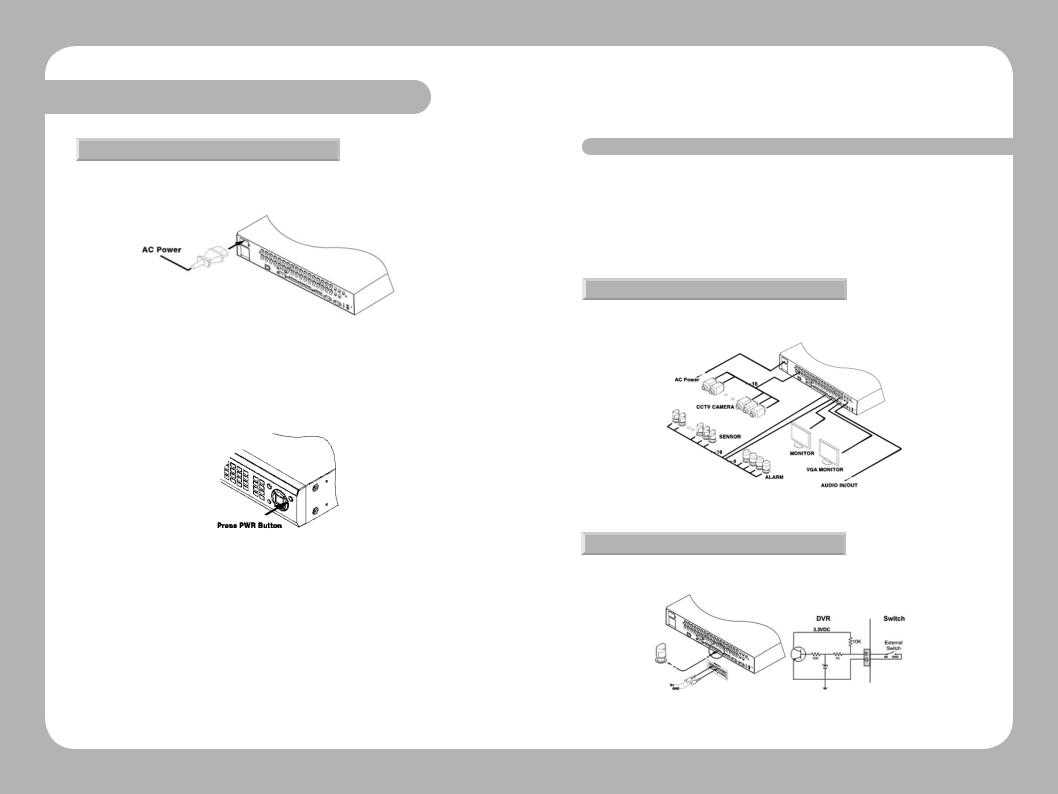
Connecting the Power Cable
Connect the power cable as shown in the following figure.
The SVR-1670 starts automatically when the power is connected.
Figure 3.3.8 Connecting a Power Cord
·To turn off the SVR-1670, press and hold the power button for 5 seconds, then choose “Yes” when the power-off dialog appears.
·You can also unplug the power cable from the power outlet to turn off the SVR-1670.
Figure 3.3.9 Turning On the SVR-1670
3. 4 Extended Connections to the SVR-1670
This section explains how to connect additional devices to the SVR-1670. It includes the following subsections :
•Extended Connection Diagram
•Sensor Connections and Settings
•Relay Connections
•D-I/O(Digital-I/O) ConnectionsAnd Settings
•Serial communication terminal connections
Extended Connection Diagram
The following picture is an example of connecting the product with a series of external devices: sensor inputs, relay outputs, D-I/O, serial communication terminals, and storage. Please refer to this example for your information.
Figure 3.4.1 Extended Connection Diagram
Sensor Connections and Settings
Connect sensors to S1 through S16. Sensors can be connected with dry contacts.
Figure 3.4.2 Sensor Connections
Digital Video Recorder 24 User Guide |
Digital Video Recorder 25 User Guide |

Chapter 3. Hardware Installation
The sensor specifications are as follows.
|
No. of inputs |
16 transistor input |
|
|
|
|
|
Specification |
Input types |
N.C, N.O support |
|
|
|
||
Support Sensor |
Dry contact sensor |
||
|
|||
|
|
|
|
|
Connection method |
Insert stripped wire end into terminal block |
|
|
|
|
|
Electric |
Pulse width of usable |
Minimum 500ms |
|
input |
|||
capacity |
|
||
|
|
||
Output power |
Typical DC 12mA |
||
|
|||
|
|
|
Relay Connections
Connect relays to R1 through R4 as illustrated in the figure below. The illustration in Figure 3.4.3 shows how to connect a warning light.
Figure 3.4.3 Relay Connections for a Warning Light
The alarm specifications are as follows.
|
No. of outputs |
4 relay outputs |
Specification |
|
|
Output type |
Dry contact |
|
|
|
|
|
Connection method |
Insert stripped wire end into terminal block |
|
|
|
Rated |
DC |
24V 1A |
current |
AC |
125V 0.5A |
|
|
|
D-I/O Connections And Settings
Connect a digital device to the D-I/O input and output terminals.
D-I/O
Figure 3.4.4 D-I/O device connection
Figure 3.4.5 Digital Input/Output Connections
The D-I/O specifications are as follows.
|
No. of inputs/outputs |
12 |
Specification |
|
|
Output type |
DC 3V output |
|
|
|
|
|
Connection method |
Connect stripped wire end with 15 pin D_SUB. |
|
|
|
Rated current |
DC |
3.3 V |
|
|
|
Digital Video Recorder 26 User Guide |
Digital Video Recorder 27 User Guide |
Chapter 3. Hardware Installation
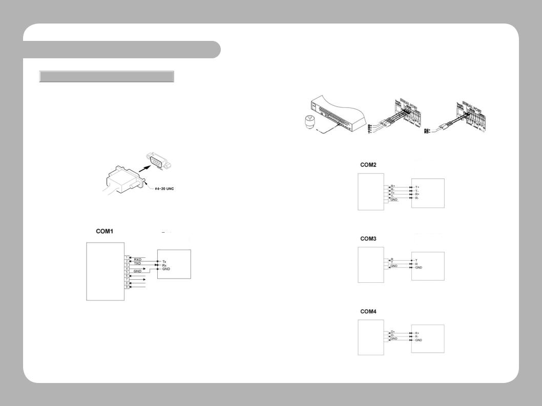
Serial communication terminal connections
Several types of devices can be connected to the SVR-1670 through serial ports. Access control, ATM, and PoS transaction data can be transmitted through the COM1 port. PTZ cameras can be connected and operated through the COM2 or COM4 ports.
Connecting Access Control, ATM, or PoS Devices
Use an RS-232 cable to connect text and video data from PoS orATM terminals through the COM1 port. COM1/RS-232 (9-pin D-SUB) is used to receive text data.
Figure 3.4.6 ATM, PoS, Access Control Connections
Text
Keyboard
Figure 3.4.7 COM1 Connection (RS-232)
Connecting PTZ Cameras to the COM Ports
Use RS-422 or RS-485 ports (COM2 or COM4).
·Serial port connection terminals are also supported.
·PTZ cameras for the SVR-1670 can be connected through the COM port, and supported models configured through the onscreen display menu.
The following figures illustrate how to connect PTZ cameras through the RS-422/485 port (COM2/ COM4) and how to connect other devices through the serial port connection terminals.
Figure 3.4.8 PTZ Camera Connection (COM2 )
Keyboard
PTZ
Figure 3.4.9 COM2 Connection (RS-422/485)
Keyboard
PTZ
Figure 3.4.10 COM3 Connection (RS-232)
Keyboard
PTZ
Figure 3.4.11 COM2 Connection (RS-485)
Digital Video Recorder 28 User Guide |
Digital Video Recorder 29 User Guide |
Chapter 3. Hardware Installation
External storage connections
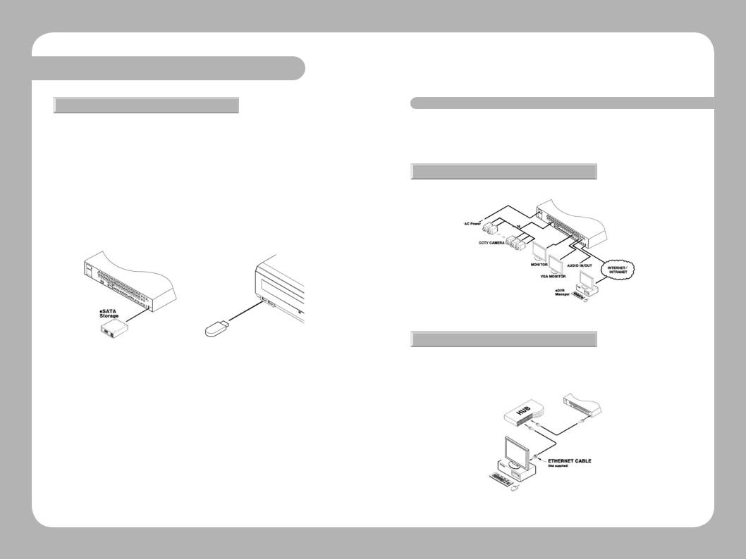
You can connect an eSATA external hard disk drive and a USB memory device to the SVR-1670. One eSATA external storage device can be connected through the eSATA port on the back panel of the SVR-1670 to expand storage to a maximum of 8TB. The eSATA port supports the Samsung Techwin SVS-5R eSATA external hard disk drive.
Connecting an eSATA Device
Turn off the SVR-1670 before you connect an external device to it.
1.After you turn off the SVR-1670, use the eSATA port on the back panel of the SVR-1670 to connect an SVS-5R external hard disk drive.
2.Attach a power cord to the drive and connect it to an external power source. If necessary, turn on the eSATA drive.
Figure 3.4.12 Connecting an eSATA Drive |
Figure 3.4.13 External Device Connections |
3.Turn on the SVR-1670.
3. 5 Remote Monitoring and Control
This section describes how to configure remote access to the SVR-1670. It contains the following subsections.
•Internet/Intranet Connection Diagram
•Ethernet Connections
Internet/Intranet Connection Diagram
Thefollowingexampleisawiringdiagramforthe SVR-1670tocontrolitremotely over theinternet or intranet.
Figure 3.5.1 Internet Connection
Ethernet Connections
Follow these steps to connect an Ethernet cable to the SVR-1670 :
1.Turn off the SVR-1670.
2.Connect one end of the Ethernet cable to the SVR-1670 and the other end to a hub or router.
Figure 3.5.2 The Ethernet Connections
Digital Video Recorder 30 User Guide |
Digital Video Recorder 31 User Guide |
Chapter 3. Hardware Installation
3.Turn on the hub or router.
4.Turn on the SVR-1670.
To prevent damage to the SVR-1670, wait to turn the power on until after you have connected the Ethernet cable.
3. 6 Hard Disk Drive Installation
This section describes how to work with a hard disk drive, in the following subsections :
•Installing a Hard Disk Drive
•Enabling a Hard Disk Drive
•Removing a Hard Disk Drive
•Disabling a Hard Disk Drive
Always turn off the SVR-1670 and unplug the power cable before you attach or remove a hard disk drive. Disconnect any devices that are connected to an external power source.
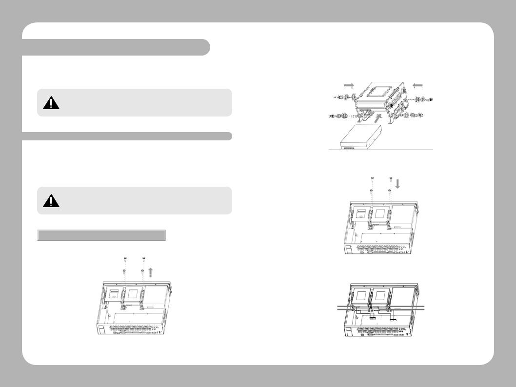
Installing a Hard Disk Drive
1.Open the upper cover of the product, and then remove the four screws that connect the hard disk drive bracket and main unit.
Figure 3.6.1 Removing Screws that Connect the SVR-1670 & Hard Disk Drive Bracket
2.Lift up the hard disk drive bracket, and then insert a hard disk. Fasten the disk to the bracket using the enclosed fixture screws, as shown in the picture below.
Figure 3.6.2 Inserting Hard Disk to the SVR-1670
3. Reattach the hard disk drive bracket to the SVR-1670 main unit.
Figure 3.6.3 Reattaching Hard Disk Drive Bracket to the SVR-1670
4. Once the bracket is securely attached,connect the SATA cable.
A D
B C
A B C D
Figure 3.6.4 Connecting SATA cable
Digital Video Recorder 32 User Guide |
Digital Video Recorder 33 User Guide |

Chapter 3. Hardware Installation
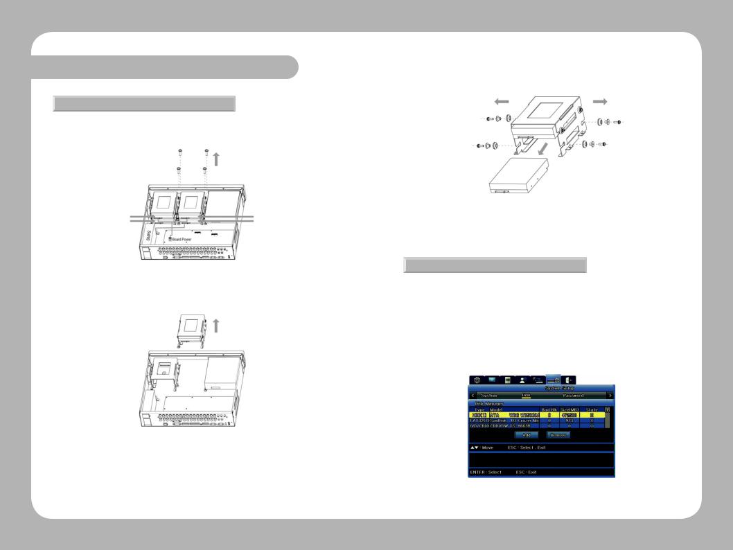
5. Connect the SMPS (switched mode power supply) power cable.
A D
B C
A B C D
Figure 3.6.5 Connecting SMPS Power Cable (Change the Image)
Figure 3.6.6 The SVR-1670 Connected with Maximum Number of HDDs
6.Close the upper cover on the SVR-1670,and then reconnect all devices that were removed for the hard drive installation.
Now,it is time to configure and activate the hard disk drive.
Enabling a Hard Disk Drive
To enable the newly attached hard disk drive,you must change its availability to " O " on the SVR-1670’s Disk Manager menu.
1.From the OSD,select the System Settings menu.
2.Select the Disk submenu,and then,on it, select Disk Manager.
-The newly installed hard disk drive appears in the list along with O and X under the State category.
Figure 3.6.7 Disk Manager Menu Showing Disabled Hard Disk Drive
3.To change to Enabled status,select the hard disk drive to connect and then press ESC to exit the Disk Selection menu.To enable the hard disk drive,selectAdd and then press Enter.You can add the hard disk drive to store data.
Figure 3.6.8 Disk Manager Menu Showing Enabled Hard Disk Drive
Digital Video Recorder 34 User Guide |
Digital Video Recorder 35 User Guide |
Chapter 3. Hardware Installation
Removing a Hard Disk Drive
To detach a hard disk drive, follow the instructions below:
1.Unplug the SATA and power cables. Remove the screws that connect the SVR-1670 main unit and the hard disk drive bracket.
A D
B C
A B C D
Figure 3.6.9 Removing Screws that Connect the SVR-1670 and Hard Disk Drive Bracket
2. Lift up the loose hard disk bracket.
Figure 3.6.10 Lifting Hard Disk Drive Bracket from the SVR-1670
3.Remove fixture screws on the both sides of the hard disk and the bracket. Store the removed fixture screws safely, so you can use them to connect a hard disk again later.
4.Push the hard disk drive out from the bracket.
Figure 3.6.11 Removing Hard Disk Drive
Now,it is time to configure and disable the hard drive from the system.
Disabling a Hard Disk Drive
To disable the removed hard disk drive,you must change its availability to " X " on the SVR1670’s Disk Manager menu.
1.From the OSD,select the System Settings menu.
2.Select the Disk submenu,and then,on it, select Disk Manager.
3.Select the removed hard disk drive,and then press ESC to exit the menu. Select Remove,and then press Enter.
4.At the confirmation message, select“Yes”to remove the hard disk drive from the list.
Figure 3.6.9 Disk Manager Menu Showing Disabled Hard Disk Drive
Digital Video Recorder 36 User Guide |
Digital Video Recorder 37 User Guide |

Chapter 4. Navigation: On-Screen Display and Function Menus
This chapter provides information about using the two graphical user interfaces for the Samsung
SVR -1670 DVR—the On-Screen Display and the Function menu.
The On-Screen Display (OSD) provides access to all SVR-1670 features and settings through a series of menus, submenus and options.
The Function Key menu provides access to all SVR-1670 functions,such as operation of cameras and manipulation of recorded video, through a main menu with icons.
You can access both the OSD and Function menu using the buttons on the SVR-1670 front panel, the mouse, or by using the remote control device.
The information is presented in these sections :
4. 1Working with the On-Screen Display
4. 2Working with the Function Menu
4.1 Working with the On-Screen Display
You will use the OSD to set up, configure and operate the SVR-1670. The section discusses how to work with the OSD and covers the following topics :
•Accessing the OSD
•Understanding the Menu Structure
•Using the On-Screen Keyboard
•Setting the Date and Time
•SavingYour Changes on the OSD
Accessing the OSD
To access the OSD,you can either :
·Press the MENU button on the front panel.To close it,press the ESC button.
·Press the Menu button on the remote control.To close it,press the ESC button.
·Press the“Home”icon on the Function menu.To close it,press the ESC button.
OSD Screen Elements
The OSD contains a row of tabs at the top with icons representing seven menus—Quick Setup, Display,Record (HDD),Event,Communications,System Setup,and Exit.
Quick Setup Display Setup Record Setup Event Setup Network Setup System Setup |
Exit |
Quick |
Event |
Exit |
Quick Setup |
Event |
Save |
Program |
Normal |
Do not save |
Event Check |
Preset |
|
Language |
D-I/O |
|
Time |
|
|
|
|
|
Audio Recording |
|
|
Display |
Comm. |
Channel Display |
Network |
Monitor1 |
DDNS |
SPOT |
NTP |
|
Remote |
|
Streaming |
|
IP Filter |
Record |
System |
Record |
System |
Program |
Disk |
|
Password |
Figure 4.1.1 The On Screen Display
Each menu has a gray title bar with submenus,demonstrated in Figure 4.1.2 :
 Menu tab(Icon)
Submenu
Option |
Setting |
Figure 4.1.2 The OSD Menu Structure
Notice that on the submenu,options are listed on the left side of the screen,with settings to the right.
As you work on the OSD you will quickly learn how to use your preferred method of moving from menus, options and settings. This table gives you the basic instructions you need to know to get started.
Digital Video Recorder 38 User Guide |
Digital Video Recorder 39 User Guide |
 Loading...