


Digital Video Recorder 1 User’s Manual

Introduction
Thank you for purchasing the SVR-940/450.
This is a user manual for SVR-940/450.Before product installation and operation,please become thoroughly familiar with this user manual and other manuals referenced by this manual.
This user manual and the software and hardware described here are protected by the copyright law.Therefore, with the exception of copying for general use within the copyright law, copying and reprinting the user manual, either partially or in its entirety, or translating it into another language without the consent of Samsung Techwin, Inc. is prohibited.
This specification may be changed without prior notice for improvement of product performance.
Product warranty and limits of responsibility
The manufacturer does not assume any other responsibility concerning the sale of this product and does not delegate any right to a third party to take any responsibility on its behalf. Product warranty does not cover cases of accidents, negligence, alteration, misuse or abuse. In addition, no warranty is offered for any attachments or parts not supplied by the
manufacturer.
The warranty period for this product will be for 3 years from the date of purchase.
The following cases are not covered by the warranty and payment is required for repairs.
•Malfunction due to negligence in handling by the user
•Deliberate disassembly and replacement by the user
•Connection of a power source other than a properly rated power source
•Malfunction caused by natural disasters (fire,flood,tidal wave,etc.)
•Replacement of expendable parts(HDD,FAN,etc.)
Warranty only refers to the warranty covering products that have been paid for.
After expiration of the warranty period (3 years), examination and repair will be provided for a fee. Even during the warranty period, repair and examination of items outside the preceding warranty scope will require a payment.
Please inquire at the point of purchase or the local service center for repairs requiring a
payment.
* This manual is made by firmware version 1.0.0 basis.
Digital Video Recorder 2 User’s Manual

Table of contents
Introduction·····························································································································································2 Product warranty and limits of responsibility····························································································2
Chapter 1. Safety Cautions································································································································5
Chapter 2.Summary·············································································································································7
2.1Features······························································································································································7
2.2Contents·····························································································································································9
2.2.1Control panel on the front···················································································································9
2.2.2Rear Connection terminals················································································································12
2.2.3Remote controller·································································································································13 2.3 Specification···············································································································································13
Chapter 3.installation········································································································································18
3.1How to connect all parts····························································································································18
3.2Detailed connection····································································································································19
3.2.1Camera······················································································································································19
3.2.2Audio··························································································································································19
3.2.3Monitor·····················································································································································20
3.2.4External connector·······························································································································21
Chapter 4.Operating··········································································································································25
4.1Checklist before operation·······················································································································25
4.2Power connection········································································································································26
4.3Live monitoring screen······························································································································26
4.3.1 Function of screen display·····················································································································27
4.3.2 Automatic channel rotation··················································································································27
4.4Recording························································································································································28
4.4.1Normal recording··································································································································28
4.4.2Scheduled recording···························································································································28
4.5Search·······························································································································································29
4.5.1Event search············································································································································29
4.5.2Timeline search······································································································································29
4.5.3Go To search············································································································································30
4.5.4Go first search·········································································································································30
4.5.5Go last search··········································································································································30
4.5.6Log file search·········································································································································31
4.5.7COPY List··················································································································································31
4.6Playback···························································································································································33
4.7PTZ·····································································································································································33
4.7.1PAN/TILT····················································································································································34
4.7.2ZOOM/FOCUS·········································································································································34
4.7.3INITIALIZE·················································································································································34
4.8DVR Backup File Player·······························································································································35
Chapter 5.Configuration··································································································································37
5.1Menu configuration·····································································································································37
5.2Default Setup·················································································································································39
Digital Video Recorder 3 User’s Manual

Table of contents
5.3Menu Screen Setup·····································································································································42
5.4SCREEN SETUP···············································································································································43
5.4.1CH1~CH4 / CH1~CH9 (for SVR-940)·······························································································43
5.4.2AUTO SEQUENCE···································································································································44
5.4.3STATUS DISPLAY·····································································································································44
5.4.4SPOT···························································································································································45
5.5RECORD SETUP··············································································································································46
5.5.1GENERAL SETUP·····································································································································46
5.5.2DETAIL SETUP·········································································································································47
5.6EVENT SETUP··················································································································································48
5.6.1EVENT·························································································································································48
5.6.2MOTION DETECTION····························································································································49
5.6.3TEXT····························································································································································49
5.6.4POS quick guide·····································································································································50
5.6.5RELAY·························································································································································51
5.7NETWORK························································································································································52
5.7.1NETWORK·················································································································································52
5.7.2DDNS Register········································································································································52
5.7.3Client access············································································································································53
5.7.4RS-232························································································································································54
5.7.5RS-422/485···············································································································································54
5.7.6E-MAIL························································································································································54
5.8DDNS Registration·······································································································································55
5.8.1.DDNS Registration procedure·········································································································55
5.9.Instructions on using DDNS····················································································································59
5.10Editing registered product·····················································································································61
5.11System setting·············································································································································62
5.11.1System·····················································································································································62
5.11.2HDD··························································································································································63
5.11.3Password················································································································································64
5.11.4User Authentication···························································································································64
5.11.5CLOCK SETUP·······································································································································65
5.12PTZ··································································································································································67
5.12.1Setting for each channel··················································································································67
5.13EXIT MENU····················································································································································67
5.14ETC···································································································································································68
5.14.1Firmware Upgrade·····························································································································68
5.14.2Index Start Fail·····································································································································69
Chapter 6.Web-Viewer······································································································································70
6.1Log page··························································································································································71
6.2LIVE mode·······················································································································································71
6.3SEARCH mode················································································································································73
6.4Web-Viewer buttons···································································································································74
Chapter 7.Troubleshooting·····························································································································76
Appendix Information of HDD Installation··························································································78
Digital Video Recorder 4 User’s Manual

Chapter 1.Safety Cautions
Symbols displayed for each item
 Warning
 Caution
Refers to information users need to know in order to prevent serious injury or death.
Provides information users need to know in order to prevent minor injury or product damage.
•Before installation
-Verify the supplied voltage (AC100V~AC240V) before connecting the power supply.
-Make sure the power supply is off before installation.
-Do not install in a very humid environment. Doing so may cause an electric shock or fire.
-Make sure ground line is connected to reduce electric shock risk.
•During operation
-Do not open the product cover except qualified personnel or system installer. Opening the product cover may cause an electric shock.
-Do not plug multiple appliances into one power outlet. Doing so may cause fire.
-Do not place dishes containing water or heavy objects on the product. Doing so may cause a malfunction.
-Do not use in areas containing inflammable materials like propane gas and gasoline or in areas that generate dust. Doing so may cause an explosion or fire.
-Do not touch the power line with a wet hand. Doing so may cause an electric shock.
-Do not insert a hand into the opening of the DVD. Doing so may cause an injury.
-Make sure conduction materials do not enter the cooling ventilator opening.
-Do not apply excessive force when pulling on the power cord. Damaging the cord may cause an electric shock or fire.
-Random replacement of built-in battery by other types of batteries may cause explosion.
-The battery shall be replaced by the same battery.
-The used batteries shall be disposed carefully because they can cause environment pollutions.
•Dismantling and cleaning
-Do not dismantle, repair or modify the product deliberately. Doing so may cause a damage, an electric shock or an injury.
-Do not use water, thinner or organic solvent for cleaning the product exterior. Doing so may cause a malfunction or an electric shock. Use a dry cloth to clean the exterior.
•During installation
-To get adequate ventilation, install the product with at least 15cm of space between the cooling ventilation opening and a wall.
-To prevent falling, install the product in a flat area . Dropping the product may cause an injury or a malfunction.
-Avoid areas exposed to sun light or heat since they may cause deformation or a malfunction.
-If a camera is installed while the DVR is recording,image in another channel may be disrupted.Start the storage after installing the camera is recommended.
Digital Video Recorder 5 User’s Manual

Chapter 1.Safety Cautions
•During use
-Make sure the product is not exposed to shocks or shaking when using the product or during moving.
-Do not move the product while it is in operation, and apply strong shocks to the product or throw the product.
-If hard disk drives other than those recommended are used additionally, abnormal operation may occur. Inquire at the point of purchase of the product before installing such a hard disk drive.
-Product warranty will not cover deliberate additional use of such hard disk drives.
-This product is a supplementary rather than primary means for preventing fire and theft.Our company
FCC Compliance Statement Caution
Any changes or modification in construction of this device which are not expressly approved the party responsible for compliance could void the user’s authority to operate the equipment.
NOTE
This equipment has been tested and found to comply with the limits for a Class A digital device, pursuant to part 15 of the FCC Rules. These limits are designed to provide reasonable protection against harmful interference when the equipment is operated in a commercial environment.This equipment generates,uses,and can radiate radio frequency energy and, if not installed and used in accordance with the instruction manual, may cause harmful interference to radio communications.Operation of this equipment in a residential area is likely to cause harmful interference in which cause the user will be required to correct the interference at his own expense.
Samsung Techwin recommends the installation of a UPS (Uninterrupted Power Supply) with all its recording products.
Samsung Techwin cares for the environment at all product manufacturing stages to preserve the environment, and is taking a number of steps to provide customers with more environment-friendly products.The Eco mark represents Samsung Techwin s will to create environment-friendly products, and indicates that the product satisfies the EU RoHS Directive.
Digital Video Recorder 6 User’s Manual

Chapter 2.Summary
The Samsung SVR-940/SVR-450 is a digital video recorder designed to be used as a security device in small shops,convenience stores,banks,ATMs,etc.It is a stand-alone device,securing system performance and safety. The Samsung SVR-940/SVR-450 saves video images on an
HDD instead of on videotape. It can save quality images even with repeated recording, and facilitates data search by recording and playing video data in a digital file format. Moreover, the Samsung SVR-940/SVR-450 is a user-oriented digital unit with high quality moving pictures and high capacity storage media. It has a variety of functions such as motion detection,
PTZ (Pan, Tilt and Zoom) control, password setting, real-time voice data storage, and event lists and log file storage.
2.1 Features
Monitoring Screen
Recording
The Samsung SVR-940/SVR-450 can record up to 120 frames per second. It also records events on an event list as well as providing a pre-event recording function.
. Simultaneous execution of three functions: recording, playback, and networking
.Convenient setting of recording frame by channel.
. Up to 3 levels of image quality setting available.
. Simple setting of the scope of motion detection.
.Recording setting up to a Maximum 120 frames per second.(Based on 360X240)
. Manual and scheduled recording.
. Event recording using external alarms and the motion detection function.
.Creating event lists for external alarms and motion detection.
. Recording images before the occurrence of events.
Playback
Digital Video Recorder 7 User’s Manual

Chapter 2.Summary
Storage Media
The built-in HDD is the basic memory supply. Using a USB memory stick or external CD-RW (guaranteed for the recommended models only), users can copy images from the internal HDD.
.Basic Memory Supply:Built-in HDD
. Backup media: USB memory stick
.Backup media:Built-in CD-RW
•CD-RW-Maker :LITEON CO.,LTD
Model : LTR-52327SX
Model :SHM-165P6SX02C
• CD MEDIA-Maker :SAMSUNG
Model : PLEOMAX R80X-
Network
The Samsung SVR-940/SVR-450 supports a wide range of networks such as LAN and ADSL, DHCP. The user can also easily operate and manage the main functions of the unit from a remote location using an exclusive PC viewer.
.Live image view from a remote location available (full screen, quad screen, and 9-channel screen mode (for SVR-940) selectable).
. Search and playback by time or event from a remote location.
. 10/100Mbps Ethernet/xDSL supported.
.DDNS supported.
Other
. Simple firmware upgrade using USB memory.
. Up to 4 channel voice recording in real time
.VGA output supported
. Menu language-selectable.
Digital Video Recorder 8 User’s Manual
Chapter 2.Summary
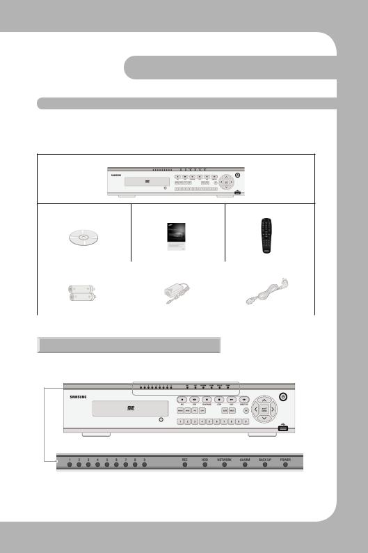
2.2 Contents
The SVR-940/SVR-450 package contains the main unit and its components as specified below. When you purchase the unit, please check that the components specified below are included. If any components are missing, please contact your local vendor.
SVR-450/940 Main unit
1.Network viewer program CD |
2. User Manual |
3. Remote controller |
4. Batteries for remote controller |
5.Adaptor (For SVR-450) |
9. Power cable |
|
|
|
2.2.1 Control panel on the front
Digital Video Recorder 9 User’s Manual

Chapter 2.Summary
LED Indication
Number |
LED Name |
Description |
|
|
|
1 |
|
Lights up when power is applied to the system |
|
|
|
2 |
|
Lights up when the system is backing up. |
|
|
|
3 |
|
Lights up when an Alarm is triggered. |
|
|
|
|
|
Lights up when client has connected to the system through |
4 |
|
the |
|
|
Network |
|
|
|
5 |
|
Lights up when the system is accessing HDD |
|
|
|
6 |
|
Lights up when the system is recording video data |
|
|
|
Button Indication
Number |
Button Name |
Description |
|
|
|
1 |
|
Press to power the system ON/OFF. |
|
|
|
2 |
|
Press to navigate to and select a Menu item. |
|
|
|
|
|
Press to select and change the forward or back playback. |
3 |
|
Pressing this button during forward playback reverses the |
|
|
direction of play. |
|
|
|
4 |
|
Forward Playback.Speeds of 2X,4X,8X. |
|
|
|
5 |
|
Press to stop the Playback and to start searching other |
|
recorded data. |
|
|
|
|
|
|
|
6 |
|
Press to Play and pause the Playback screen |
|
|
|
Digital Video Recorder 10 User’s Manual
|
|
Chapter 2.Summary |
Button Indica- |
|
|
|
|
|
Number |
Button Name |
Description |
|
|
|
7 |
|
Playback position moves 1 frame forward/back during |
|
Pause. |
|
|
|
|
|
|
|
8 |
|
Press to start and stop manual recording |
|
|
|
9 |
|
Press to search the recorded data |
|
|
|
10 |
|
Press to launch Setup Menu |
|
|
|
11 |
|
Press to control the PTZ functions |
|
|
|
12 |
|
Press to backup still images or video |
|
|
|
13 |
|
Press to start screen Auto Sequence.Set °ÆSCREEN SETUP/ |
|
AUTO SEQUENCE/SEQUENCE°Ø as °ÆON°Ø. |
|
|
|
|
|
|
|
14 |
|
Press to select the live display format as full screen, quad |
|
screen,or 9-channel screen (for SVR-940) display. |
|
|
|
|
|
|
|
15 |
|
Press to return to previous Menu screen. |
|
|
|
16 |
|
Press to move up in a Menu item in setup mode. |
|
|
|
17 |
|
Press to move right in a Menu item in setup mode. |
|
|
|
18 |
|
Press to move down in a Menu item in setup mode. |
|
|
|
19 |
|
Press to move left in a Menu item in setup mode. |
|
|
|
|
|
Press to select full screen, quad screen, or 9-channel screen |
20 |
|
(for SVR-940) in live monitoring mode.It can also be used |
|
to select a desired menu item or to store a setup value in |
|
|
|
|
|
|
the menu. |
|
|
|
21 |
|
USB Backup and Firmware upgrade. |
|
|
|
Digital Video Recorder 11 User’s Manual
Chapter 2.Summary
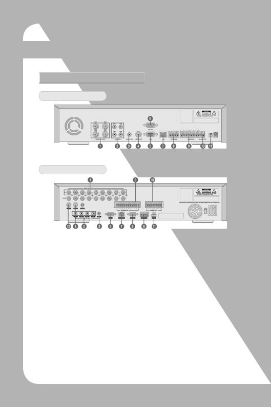
2.2.2 Rear Connection terminals
Rear panel of SVR-450
Rear panel of SVR-940
1.VIDEO IN |
Camera Input (NTSC/PAL) |
2.AUDIO IN |
Audio Input |
3.AUDIO OUT |
Audio Output |
4.VIDEO OUT |
Composite Video Output |
5.VGA |
VGA output |
6.RS-232 |
For the engineering console only,not for other purposes. |
7.LAN |
RJ45 Connector |
8. RS-485/422 |
PTZ camera control |
9.SENSOR IN |
Sensor Input |
10.ALARM OUT Alarm Output |
|
11.SWITCHES |
NTSC/PAL,BNC/VGA Select Switch(Please refer to Chapter 5 for the detailed |
|
guide.) |
12.SPOT |
Spot output (For SVR-940) |
13.SVHS |
S-VHS output |
Digital Video Recorder 12 User’s Manual
|
Chapter 2.Summary |
|||
|
|
|
|
|
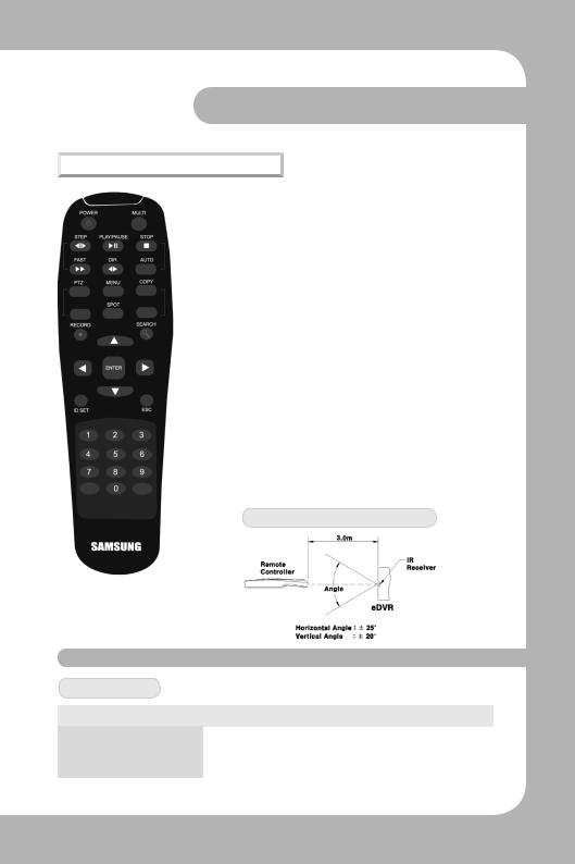
2.2.3 Remote controller |
|
|
|
|
• MENU |
Button to enter Setup Menu |
|
||
• AUTO |
For Auto Sequence |
|
||
• SPOT |
Button for Spot ON/OFF (SVR-940.) |
|||
• PTZ |
Button for PTZ camera control. |
|
||
• COPY |
Button for data backup. |
|
||
• RECORD |
Button for Manual record ON/OFF. |
|||
• STOP |
Button to stop playback. |
|
||
• SEARCH |
Button for search menu. |
|
||
• STEP |
Playback position moves 1 frame forward/back |
|||
|
during Pause. |
|
||
• PLAY/PAUSE Button to Play and Pause the Playback screen |
||||
• FAST |
Button for Forward Playback.Speeds of 2X,4X,8X. |
|||
• DIR |
Button to select and change the direction of play |
|||
in |
playback. When pressed during forward play- |
|||
back, |
||||
the system reverses the direction of play. |
||||
|
||||
• ENTER |
Button to select full screen, |
quad screen, or |
||
|
9-channel screen (for SVR-940) |
in live monitor- |
||
|
ing mode. |
|
||
or |
It can also be used to select a desired menu item |
|||
to store a setup value in the menu. |
||||
|
||||
• MULTI |
Button to select the live display format as full |
|||
screen, |
quad screen, or 9-channel screen (for SVR-940) |
|||
|
||||
|
display. |
|
||
UsablerangeofRemoteController
2.3 Specification
System
Items |
SVR-450 |
|
SVR-940 |
|
|
|
|
Processor |
|
DSP |
|
Operating system (O/S) |
|
RTOS |
|
Compression method |
|
MPEG-4 |
|
Digital Video Recorder 13 User’s Manual

Chapter 2.Summary
Video
Items |
SVR-450 |
SVR-940 |
|
|
|
|
|
Input Method |
Composite Input 4-Channel |
Composite Input 9-Channel |
|
|
|
|
|
Video Input Level |
1.0 Vp-p,Composite |
||
|
|
||
Live Screen Display Speed |
Real time display |
||
|
|
||
|
NTSC:720 (W) _ 480 (H) Pixels for the full screen. |
||
Live Screen |
PAL:720 (W) _ 576 (H) Pixels for the full screen |
||
8bit Brightness (256 Gray Scale) |
|||
|
|||
|
24bit Color (160,000 Colors) |
||
|
|
|
|
Monitor Output |
1.0Vp-p Composite,75Ω |
1.0Vp-p Composite,75Ω / |
|
S-VHS |
|||
|
|
||
|
|
|
|
VGA Output |
RGB Output (Non-Interlaced Scan) |
||
* Select composite or VGA |
|||
|
|||
|
|
|
|
Audio
Items |
SVR-450 |
|
SVR-940 |
|
|
|
|
Audio |
|
4CH Audio Input |
|
|
1CH Audio Output |
||
|
|
||
|
|
|
|
Audio compression |
|
ADPCM |
|
|
|
|
|
Alarm
Items |
SVR-450 |
SVR-940 |
|
|
|
Input |
4 Channels |
9 Channels |
|
|
|
Output |
1 Relay output |
4 Relay output |
|
|
|
Control
Items |
SVR-450 |
|
SVR-940 |
|
|
|
|
Remote controller |
Infrared LED (Up to 5m) |
||
|
|
|
|
Exclusive controller |
|
SCC-3100A (RS-485) |
|
|
|
|
|
Digital Video Recorder 14 User’s Manual

Chapter 2.Summary
Recording
Items |
SVR-450 |
SVR-940 |
|
|
|
|
|
Maximum Number of |
|
720X480:30 Frames/Sec |
|
Frames |
720X480:30 Frames/Sec |
||
720X240 :60 Frames/Sec |
|||
Sec per Resolution |
360X240:120 Frames/Sec |
||
360X240:120 Frames/Sec |
|||
(NTSC) |
|
||
|
|
||
|
|
|
|
Recording Method |
3 Types of Recording Mode: General, Schedule, & Event |
||
Pre-Event Recording |
Individual Channel ON/OFF Setting |
||
Image Quality |
3-Stage Image Quality:User Configurable |
||
|
|
|
|
HDD
Items |
SVR-450 |
|
SVR-940 |
|
|
|
|
Default HDD |
1 ea (Max.1ea) |
|
1 ea (Max.2ea) |
|
|
|
|
HDD type |
|
EIDE |
|
RPM |
|
7200rpm |
|
Recommended |
Samsung / Seagate / Maxtor |
||
|
|
|
|
 Notes • Please refer to the recommended HDD model list.
Backup
Items |
SVR-450 |
SVR-940 |
|
|
|
Digital Backup |
USB Memory Stick / Built-in CD-RW (DVD) |
|
|
|
|
Password
Items |
SVR-450 |
SVR-940 |
|
|
|
4-digit Password (including four numbers) 6 stage Password Admin :Control all function (Default is 1111)
USER1~5:Access permission per option (Default is 1111)
Digital Video Recorder 15 User’s Manual

Chapter 2.Summary
Search and Playback
Items |
SVR-450 |
|
SVR-940 |
|
|
|
|
||
|
Search by Time:Year,Month,Date,Hour,Minute |
|||
|
Search by Channel:per channel |
|||
Search Mode |
Search by Event:Alarm,Motion Detect |
|||
Search by the oldest data:The first recording image |
||||
|
||||
|
Search by the most recent data:The last recording image |
|||
|
Search by bar: Using the search bar |
|||
|
|
|
|
|
Speed & direction of |
|
Forward and Reverse |
||
Playback |
|
|||
|
|
|
||
|
|
|||
Fast Search |
Rewind (X2,X4,X8),Rewind (X2,X4,X8) |
|||
|
|
|||
STEP Search |
Search in 1 second increments |
|||
|
|
|||
Pause and Frame Playback |
Playback pause, Playback by frame in the pause status |
|||
|
|
|
|
|
Network
Items |
SVR-450 |
SVR-940 |
|
|
|
Live Screen: Monitoring
Playback Screen: Search
Menu Setting:Menu setting available (CMS S/W :option)
General Access Method:Dedicated Viewer Protocol:TCP/IP,DHCP
Interface: Ethernet (10/100Mbps),ADSL Concurrent Users:Up to 4 users (depending on the net-
work environment)
Electrical Specification
Items |
SVR-450 |
SVR-940 |
|
|
|
|
|
Power |
DC 12V Adaptor (SVR-450) |
100~127V/200~240V, |
|
50/60Hz |
|||
|
|
||
|
|
|
Digital Video Recorder 16 User’s Manual

Chapter 2.Summary
User Environment
Items |
SVR-450 |
|
SVR-940 |
|
|
|
|
Operating Temperature |
|
5˚C~ 40˚C |
|
Storage Temperature |
|
10˚C~60˚C |
|
Humidity |
30% ~90%(without dewfall) |
||
|
|
|
|
Exterior
Items |
SVR-450 |
|
SVR-940 |
|
|
|
|
Material |
|
Steel Case |
|
Dimensions |
260(W) X 350(D) X 65(H)mm |
||
|
|
|
|
Weight |
About 5.5Kg |
|
11Kg |
|
|
|
|
ConnectionTerminals
Items |
SVR-450 |
|
SVR-940 |
|
|
|
|
Video Input |
BNC(4EA) |
|
BNC(9EA) |
|
|
|
|
Monitor Output |
BNC(1EA) |
|
Loop out (9EA),Spot (1EA) |
|
S-VHS |
||
|
|
|
|
|
|
|
|
|
|
15-Pin DSUB |
|
VGA Output (PC Monitor) |
RCA Input (4),RCA Output (1) |
||
Audio Jack |
USB2.0 (Firmware Upgrade/Copy) |
||
USB Port |
|
RS-232C (Standby) |
|
9-Pin DSUB |
RS-422/485 (External control,PTZ) |
||
6-Pin Terminal sector |
Alarm Input Terminal |
||
8-Pin Terminal sector |
Alarm Output Terminal (Motion Detect,Sensor:CM,NO, |
||
2-Pin Terminal sector |
|
NC) |
|
Termination Switch (JP2 |
RS-422/485 Terminal Resistance Switch (RS-422/485 |
||
Termination) |
termination can be set using jump setting after opening |
||
LAN Input |
|
the top cover) |
|
|
|
RJ-45(Network) |
|
|
|
|
|
Accessories |
|
|
|
|
|
|
|
Items |
SVR-450 |
|
SVR-940 |
|
|
|
|
|
Network Viewer Program CD |
||
|
|
User Manual |
|
Accessories to be supplied |
Remote Control & Battery |
||
|
Brackets and screws for HDD plate |
||
|
Adaptor (for SVR-450),Power cable |
||
|
|
|
|
Digital Video Recorder 17 User’s Manual
Chapter 3.Installation
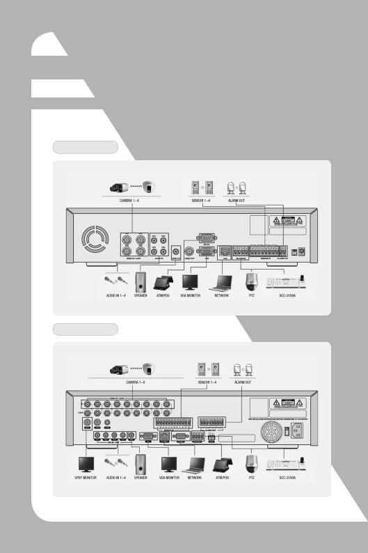
3.1 How to connect all parts
The connection layouts for the SVR-450/940 with the monitor,CCTV,and external devices are described as below.
SVR-450
SVR-940
Digital Video Recorder 18 User’s Manual
Chapter 3.Installation
3.2 Detailed connection
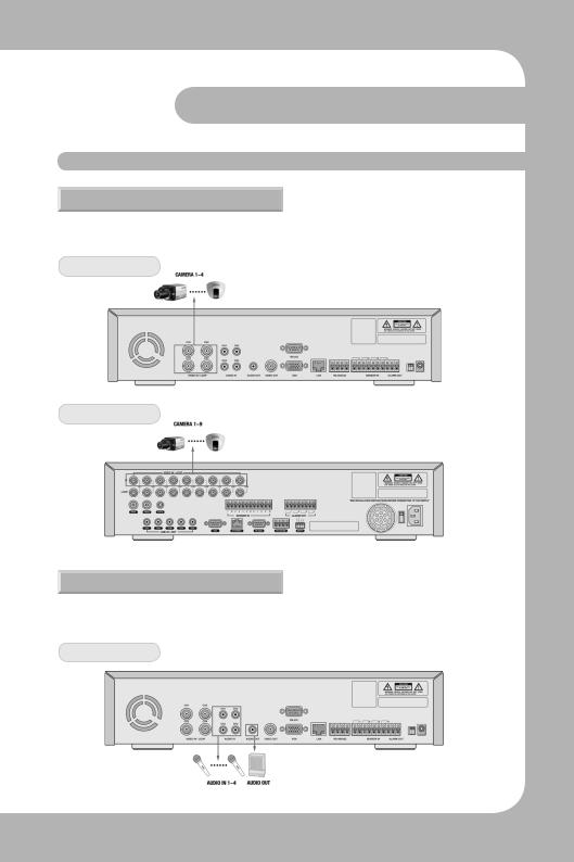
3.2.1 Camera
The SVR-450 and 950 can accommodate up to 4 or 9 cameras respectively.Connect the BNC terminal of each camera to the CAMERA IN terminal of the unit.
SVR-450
SVR-940
3.2.2 Audio
The SVR-450/950 can save audio information.For storage or output of audio information,it is required to connect the relevant devices.
SVR-450
Digital Video Recorder 19 User’s Manual
Chapter 3.Installation
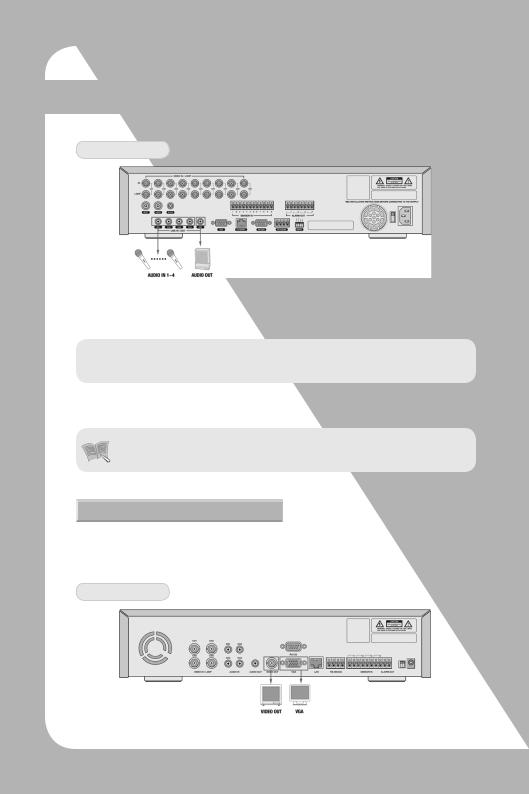
SVR-940
Audio input
Please connect an RCA audio cable to the AUDIO IN connector (such as camera with built-in microphone and others).(All types of microphone and speaker are compatible with the
 Notes • For Audio input setting,set [Audio] to [ON] in the Recording setting menu
Please connect an RCA audio cable to the AUDIO OUTPUT connector (such as monitor with built-in speakers).
Notes |
• When playback with audio in split display mode is not working properly, |
|
turn the display mode to Full screen to avoid an audio playback problem. |
3.2.3 Monitor
Connect the VIDEO OUT terminal of the system and the BNC terminal of the monitor,using the BNC cable,in order to display video data to the main monitor.There is also a VGA video output for the PC monitor.
SVR-450
Digital Video Recorder 20 User’s Manual
Chapter 3.Installation
SVR-940
|
• The Video output and the VGA output cannot be used at the same time |
|
and the system can send only one video out at the same time. Please refer |
Caution |
to Chapter 4.1 Checklist before operation for the setting of monitor selec- |
|
tion. |
|
• During playback with the VGA monitor, a few frames can sometimes be |
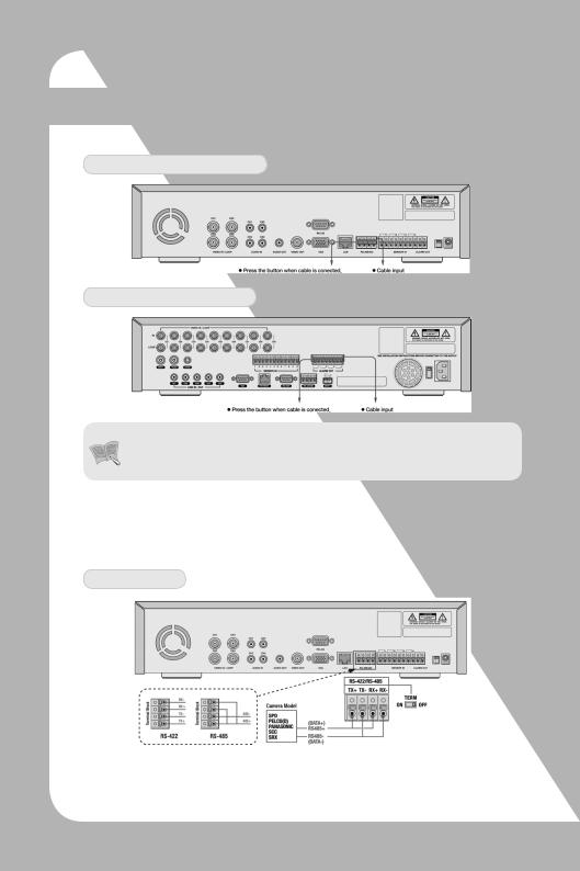
3.2.4 External connector
Sensor input (SENSOR IN)
SVR-450 (4-SENDOR IN)
SVR-940 (9-SENDOR IN)
As external sensor connecting terminal,signals from an external sensor or device will be input to the system.
Relay Output (RELAY OUT)
This Alarm Output terminal uses the contact relay for the alarm output to external devices. You can select NO (Normal Open) or NC (Normal Close) for connection according to the contact point status.
Digital Video Recorder 21 User’s Manual
Chapter 3.Installation
SVR-450 (1-ALARM OUT)
SVR-940 (4-ALARM OUT)
• The operation of each relay output can be defined by a combination of Mo-
Notes tion Detect, and Sensor in the Event Setting on the Main Menu. See Paragraph 4.5.3 CH1~CH4 Relay Setting for details
External Control Device Terminal (RS-422/485)
This terminal is connected to external control devices.The internal JP2 termination terminal turns the terminator resistance of the RS-422/485 communication device on and off.
(In the SWITCH section on the back of the SVR-940 there is a TERM switch.)
SVR-450
1.RS-422 :Connecting Terminal Block's 4 Port orderly
2.RS-485 :ShorttheTerminalBlock's1&3(Tx+Rx+)Ports,and2&4ports(Tx-,Rx-),thenconnecting
1 & 2 ports or 3 & 4 ports to RS-485
Digital Video Recorder 22 User’s Manual
Chapter 3.Installation
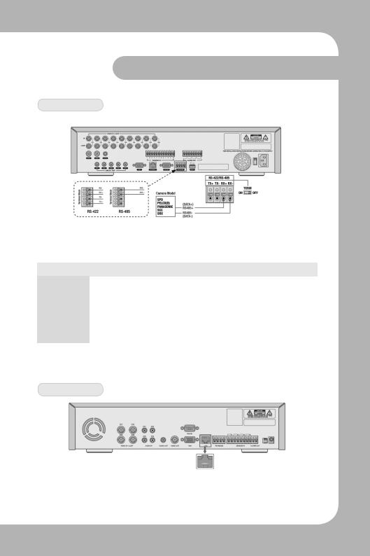
SVR-940
1.RS-422 :Connecting Terminal Block's 4 Port orderly
2.RS-485 :Connecting 3 & 4 ports to RS-485
No. |
|
Description |
|
|
|
|
|
Classification |
RS-422 |
|
RS-485 |
|
|
|
|
1 |
TX+(+Transmit Data) |
|
- |
|
|
|
|
2 |
TX-(- Transmit Data) |
|
- |
|
|
|
|
3 |
RX+(+Receive Data) |
|
Data+ |
|
|
|
|
4 |
RX-(- Receive Data) |
|
Data- |
|
|
|
|
LAN Connection (Ethernet 10/100 Base-T)
This port is to connect to network.
SVR-450
Digital Video Recorder 23 User’s Manual

Chapter 3.Installation
SVR-940
No. |
Description |
No. |
Description |
|
|
|
|
1 |
TX+(Transmit Data) |
5 |
N/C(No connection) |
|
|
|
|
2 |
TX-(Transmit Data) |
6 |
RX-(Receive Data) |
|
|
|
|
3 |
RX+(Transmit Data) |
7 |
N/C(No connection) |
|
|
|
|
4 |
N/C(No connection) |
8 |
N/C(No connection) |
|
|
|
|
Monitor Output (VGA)
This is the output connector for a VGA Monitor.
SVR-450
SVR-940
Digital Video Recorder 24 User’s Manual

Chapter 3.Installation
No. |
Description |
No. |
Description |
|
|
|
|
|
|
1 |
Red Signal (75,0.7Vp-p) |
9 |
N/C(No connection) |
|
|
|
|
|
|
2 |
Green Signal (75,0.7Vp-p) |
10 |
Ground |
|
|
|
|
|
|
3 |
Blue Signal (75,0.7Vp-p) |
11 |
Ground |
|
|
|
|
|
|
4 |
N/C(No connection) |
12 |
N/C(No connection) |
|
|
|
|
|
|
5 |
Ground |
13 |
HSYNC (Horizontal Synchroniza- |
|
tion) |
||||
|
|
|
||
|
|
|
|
|
6 |
Ground |
14 |
VSYNC (Vertical Synchronization) |
|
|
|
|
|
|
7 |
Ground |
15 |
N/C(No connection) |
|
|
|
|
|
|
8 |
Ground |
|
|
|
|
|
|
|
Chapter 4.Operating
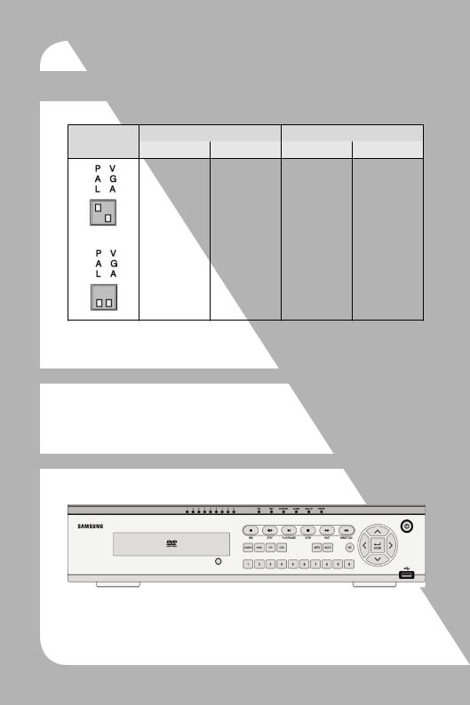
4.1 Checklist before operation
Users must select the video mode (NTSC or PAL) and video output (BNC orVGA) before powering the system on.These can be selected from the switches on the rear of the DVR system.
The settings of the video mode and video output are as described below.
SETTING |
|
Video mode |
|
Video output |
|
|
|
|
|
||
NTSC |
PAL |
BNC |
VGA |
||
|
O |
X |
O |
X |
X |
O |
O |
X |
Digital Video Recorder 25 User’s Manual
Chapter 4.Operating
SETTING |
|
Video mode |
|
Video output |
|
|
|
|
|
||
NTSC |
PAL |
BNC |
VGA |
||
|
O |
X |
X |
O |
Factory Default |
|
|
|
|
|
|
|
X |
O |
X |
O |
* The factory default is set to NTSC video mode and VGA video output.
4.2 Power connection
· After power is connected to the rear connector of the system,the system will be powered on.
· When power is turned on, the system will detect a video signal automatically.
4.3 Live monitoring screen
When the system is turned ON,the live monitoring screen is displayed.
Digital Video Recorder 26 User’s Manual
 Loading...