


NZ64M3707AK
ENGLISH
PN:16166000A20346
WARNING
CAUTION
CAUTION
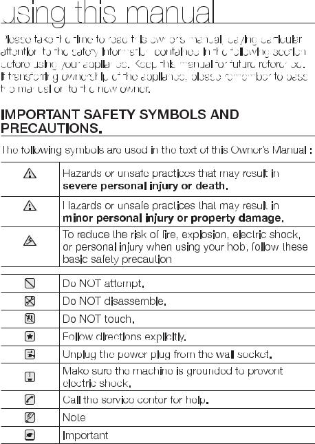
2_ using this manual
WARNING
 INSTRUCTIONS SAFETY
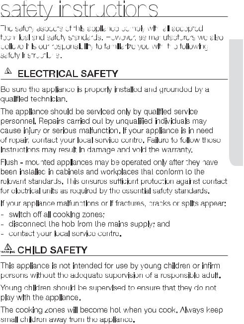
safety instructions _3
WARNING
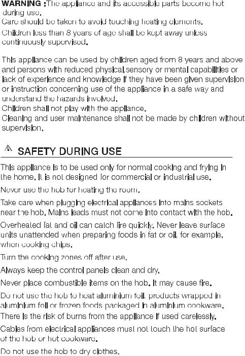
4_ safety instructions
WARNING
 INSTRUCTIONS SAFETY
WARNING SEVERE WARNING SIGNS FOR INSTALLATION
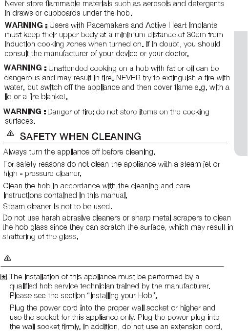
safety instructions _5

6_ safety instructions
WARNING
 INSTRUCTIONS SAFETY
- 
safety instructions _7

WARNING
8_ safety instructions

 INSTRUCTIONS SAFETY
safety instructions _9
over without warning 
10_ safety instructions
CAUTION CAUTION SIGNS FOR USING
 INSTRUCTIONS SAFETY
safety instructions _11

the lid (Model which has lid only).
12_ safety instructions
WARNING
WARNING CAUTION SIGNS FOR CLEANING
 INSTRUCTIONS SAFETY
safety instructions _13

WARNING
WARNING
CORRECT DISPOSAL OF THIS PRODUCT
(WASTE ELECTRICAL & ELECTRONIC EQUIPMENT)
14_ disposal instructions
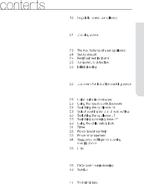
INSTALLING THE HOB
16 

PARTS AND FEATURES
21 

BEFORE YOU BEGIN
26
HOB USE
26 

CLEANING AND CARE
35 
WARRANTY AND SERVICE
38
TECHNICAL DATA
41 

 CONTENTS
contents _15

WARNING
SAFETY INSTRUCTIONS FOR THE INSTALLER
t 
t 
t  t
t  t
t 
16_ installing the hob
casing of the hob.
 Shut off power to circuit before connecting wires to WARNING circuit.
 HOB THE INSTALLING
WARNING
WARNING
installing the hob _17

WARNING
WARNING
|
t 1N ~ |
|
|
|
|
|
|
|
|
|
|
|
|
|
|
|
|
|
|
|
|
|
|
|
t 2N ~ : Separate the 2-phase |
|||||||||||||||||||||||||||||
|
|
|
|
|
|
|
|
|
|
|
|
|
|
|
|
|
|
|
|
|
|
|
|
|
|
|
|
|
|
|
|
|
wires (L1 and L2) before |
|||||||||||||||||||||
|
|
|
|
|
|
|
|
|
|
|
|
|
|
|
|
|
|
|
|
|
|
|
|
|
|
|
|
|
|
|
|
|
connection. |
|||||||||||||||||||||
|
|
|
|
|
|
|
|
|
|
|
|
|
|
|
|
|
|
|
|
|
|
|
|
|
|
|
|
|
|
|
|
|
|
|
|
|
|
|
|
|
|
|
|
|
|
|
|
|
|
|
|
|
|
|
|
|
|
|
|
|
|
|
|
|
|
|
|
|
|
|
|
|
|
|
|
|
|
|
|
|
|
|
|
|
|
|
|
|
|
|
|
|
|
|
|
|
|
|
|
|
|
|
|
|
|
|
|
|
|
|
|
|
|
|
|
|
|
|
|
|
|
|
|
|
|
|
|
|
|
|
|
|
|
|
|
|
|
|
|
|
|
|
|
|
|
|
|
220-240V ~ |
|
|||||||||||||||
|
|
|
|
|
220-240V ~ |
|
|
|
|
|
|
|
|
|
|
|
|
|
|
|
|
|
|
|
|
|
|
|
|
|
||||||||||||||||||||||||
|
|
|
|
|
|
380-415V ~ |
|
|
|
|
|
|
|
|||||||||||||||||||||||||||||||||||||||||
|
Brown |
|
|
|
|
|
|
|
|
|
|
|
Blue |
Green/Yellow |
|
|
|
|
|
Green/Yellow |
|
|||||||||||||||||||||||||||||||||
|
|
|
|
|
|
|
|
|
|
|
|
|
|
|
|
|
|
|
|
|
|
|
|
|
|
|
|
|
|
|
||||||||||||||||||||||||
|
|
|
|
|
|
|
|
|
|
|
|
|
|
|
|
|
|
|
|
|
|
|
|
|
|
|
|
|
|
|
|
|
|
|
|
|
|
|||||||||||||||||
|
|
|
|
|
|
|
|
|
|
|
|
|
|
|
|
|
|
|
|
|
|
Brown |
|
|
|
|
|
|
|
|
|
|
|
|
|
Blue |
|
|
|
|
|
|||||||||||||
|
|
|
|
|
|
|
|
|
|
|
|
|
|
|
|
|
|
|
|
|
|
|
|
|
|
|
|
|
|
|
|
|
|
|
|
|
||||||||||||||||||
|
|
|
|
|
|
|
|
|
|
|
|
|
|
|
|
|
|
|
|
|
|
|
|
|
|
|
|
|
|
|
|
|
|
|
|
|
|
|
||||||||||||||||
|
|
|
|
|
|
|
|
|
|
|
|
|
|
|
|
|
|
|
|
|
|
|
|
|
|
|
|
|
|
|
|
|
|
|
||||||||||||||||||||
|
|
|
|
|
|
|
|
|
|
|
|
|
|
|
|
Gray |
|
|
|
|
|
|
|
|
|
|
|
|
|
|
|
|
|
|
|
|
|
|
|
|
|
|||||||||||||
|
Black |
|
|
|
|
|
|
|
|
|
|
|
|
|
|
|
|
|
|
|
|
Black |
|
|
|
|
|
|
|
|
Gray |
|
|
|
|
|
||||||||||||||||||
|
|
|
|
|
|
|
|
|
|
|
|
|
|
|
|
|
|
|
|
|
|
|
|
|
|
|
|
|
|
|
|
|
|
|
|
|
|
|
|
|||||||||||||||
|
|
|
|
|
|
|
|
|
|
|
|
|
|
|
|
|
|
|
|
|
|
|
|
|
|
|
|
|
|
|
|
|
|
|
|
|
|
|
|
|
|
|
|
|
|
|
|
|
|
|
|
|
|
|
|
|
|
|
|
|
|
|
|
|
|
|
|
|
|
|
|
|
|
|
|
|
|
|
|
|
|
|
|
|
|
|
|
|
|
|
|
|
|
|
|
|
|
|
|
|
|
|
|
|
|
|
|
|
|
|
|
|
|
|
|
|
|
|
|
|
|
|
|
|
|
|
|
|
|
|
|
|
|
|
|
|
|
|
|
|
|
|
|
|
|
|
|
|
|
|
|
|
|
|
|
|
|
|
|
|
|
|
|
|
|
|
|
|
|
|
L |
N |
|
|
|
|
|
|
|
|
|
|
|
|
|
L1 L2 |
|
|
N |
|
|
|
|
|
|
||||||||||||||||||||||||
|
|
|
|
|
|
|
|
|
|
|
|
|
|
|
|
|
|
|
|
|
|
|||||||||||||||||||||||||||||||||
|
32A |
|
|
1N ~ |
|
|
|
16A |
2N ~ |
|
||||||||||||||||||||||||||||||||||||||||||||
|
|
|
|
|
|
|
|
|
|
|
|
|
|
|
|
|
|
|
|
|
|
|
|
|
|
|
|
|
|
|
|
|
|
|
|
|
|
|
|
|
|
|
|
|
|
|
|
|
|
|
|
|
|
|
|
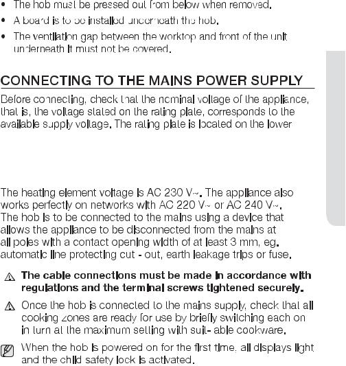
2x1N~: Separate the wires before connection. |
|||||||||||||||||||||||||||||||||||||||||||||||||||||
|
|
|
|
|
|
|
|
|
|
|
|
|
|
|
|
|
|
|
|
|
|
|
|
|
|
|
|
|
|
|
|
|
|
|
|
|
|
|
|
|
|
|||||||||||||
|
|
|
|
|
|
|
|
|
|
|
|
|
|
|
|
|
|
|
|
|
|
|
|
|
|
|
|
|
|
|
|
|
|
|
|
|
|
|
|
|
|
|
|
|
|
|
|
|
|
|
|
|
|
|
|
Blue |
|
|
|
220-240V~ 220-240V~ |
|
|
|
|
|
For correct supply connection, |
|||||||||||||||||||||||||||||||||||||||||||
|
|
|
|
|
|
|
|
|
|
|
|
|
|
|
|
|
|
|
|
|
Green/Yellow |
|
||||||||||||||||||||||||||||||||
|
|
|
|
|
|
|
|
|
|
|
|
|
|
|
|
|
|
|
|
|
|
|||||||||||||||||||||||||||||||||
|
|
|
|
|
|
|
|
|
|
|
|
|
|
|
|
Brown |
|
|
||||||||||||||||||||||||||||||||||||
|
|
|
|
|
|
|
|
|
|
|
|
|
|
|
|
|
|
|
|
|
|
|||||||||||||||||||||||||||||||||
|
|
|
|
|
|
|
|
|
|
|
|
|
|
|
|
|||||||||||||||||||||||||||||||||||||||
|
|
|
|
|
|
|
|
|
|
|
|
|
|
|
|
|
|
|
|
|
|
|
|
|
||||||||||||||||||||||||||||||
|
Black |
|
|
|
|
|
|
|
|
|
|
|
|
|
|
Gray |
WARNING follow the wiring diagram |
|||||||||||||||||||||||||||||||||||||
|
|
|
|
|
|
|
|
|
|
|
|
|
|
|
|
|
|
|
||||||||||||||||||||||||||||||||||||
attached near the terminals.
L1 N1 L2 N2
16A 2X1N~
18_ installing the hob
INS


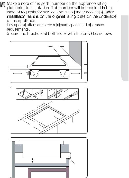
before installation.
Min. 50 mm |
Min. 2 mm |
560 mm
ø 6 |
x 4 |
90° |
|
max. 50 |
+4 |
min. 20 |
560+1 |
|
490 +4
+1 50
600
Induction Hob |
|
|
min. 2 mm |
20 mm |
|
Insulation Panel |
ventilation gap |
|
|
Oven |
|
 HOB THE INSTALLING
installing the hob _19

Install the two brackets
Put into the hole
490 +4+1
20_ installing the hob
parts and features
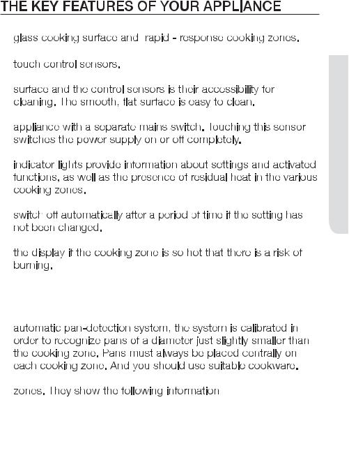
COOKING ZONES
220 |
mm |
140 |
mm |
||
3 |
|||||
|
|||||
|
|
|
|
||
|
|
|
2 |
|
|
|
mm |
220 |
mm |
||
140 |
4 |
||||
|
|
|
|||
|
|
|
|
||
|
|
1 |
|
|
|
5
 FEATURES AND PARTS
CONTROL PANEL
1
6 |
6 |
5
2 |
7 |
3 |
4 |
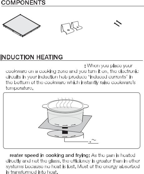
Induction hob |
|
Installation brackets |
Screws |
|
|||
|
|
|
|
t 


 Induced currents
Induction coil 


 Electronic circuits
t 
22_ parts and features
t 

t 

t 

t 


t 
t 


t 

t Power Boost  : Use this function to heat up the contents of the pan faster than maximum power level ‘
 ’. (The display will show ‘
 ’.)
’.)
t 


t 


-

- to
to  ,
, 

-

-

 FEATURES AND PARTS
parts and features _23
-


cookware)
-

 If cookware is unsuitable or too small or no cookware has
24_ parts and features

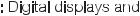
Other reasons why a cooking zone can switch itself off
the appliance will need to be switched on again using the main On/Off control  sensor after the liquid or the cloth has been removed .
RESIDUAL HEAT INDICATOR
presence of residual heat is shown with an  (for “hot”) in the
WARNING
 If the power supply is interrupted, the
  symbol will go out
WARNING
 FEATURES AND PARTS
parts and features _25

INITIAL CLEANING
Wipe the ceramic glass surface with a damp cloth and ceramic hob glass cleaner.
 Do not use caustic or abrasive cleaners. The surface could be WARNING damaged.
COOKWARE FOR INDUCTION COOKING ZONES
The induction hob can only be turned on when a cookware with a magnetic base is placed on one of the cooking zones. You can use the following suitable cookware.
Cookware material
Cookware material |
Suitable |
|
|
Steel, Enamelled steel |
Yes |
|
|
Cast iron |
Yes |
|
|
Stainless steel |
If appropriately labelled by the |
|
manufacturer |
|
|
Aluminium, Copper, Brass |
No |
|
|
Glass, Ceramic, Porcelain |
No |
|
|
Cookware for induction hob is labelled as suitable by the manufacturer.
Certain cookware can make noise when being used on induction cooking zones. These noise are not a fault in the appliance and do not affect operation in any way.
26_ before you begin

USE HOB
Diameter of cooking |
Minimum diameter of the bottom |
zones |
of the cookware |
|
|
220 mm |
140 mm |
|
|
140 mm |
120 mm |
|
|
If you can hear. t 
t 
t  t
t  t
t 
hob use _27

U


t  t
t 
t 
t 
t 
Energy saving tips
t |
|
t |
Right! |
|
|
t |
Wrong! |
t |
|
28_ hob use
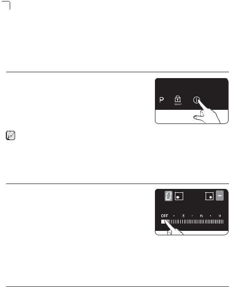
USE HOB
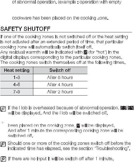
1. Touch the On/Off sensor for approximately 1 seconds.
2. The digital displays will show  .
.
 After the On/Off control
  sensor has been actuated to switch on your appliance, a heat setting must be selected within approximately 1 minutes. Otherwise, the appliance will switch itself off for safety reasons.
SELECT COOKING ZONE AND HEAT SETTING
1.For selecting the cooking zone, touch the corresponding cooking zone’s key.
2.For setting and adjusting the
power level, touch the Heat setting selectors.
hob use _29
 If more than one sensor except the slide touch key is pressed
for longer than 10 seconds, An acoustic signal will sound and
the appliance is switched off. To reset, touch the On/Off control  sensor.
SWITCHING THE APPLIANCE OFF
To completely switch off the appliance, use the On/Off control  sensor.
Touch the On/Off  sensor for approximately 1 second.
 After switching off a single cooking zone or the entire cooking surface, the presence of residual heat will be indicated in the digital displays of the corresponding cooking zones in the form of an
  (for “hot”).
SWITCHING A COOKING ZONE OFF
To switch off a cooking zone, return the setting to  by using the control panel’s

 control sensor.
USING THE CHILD SAFETY LOCK
You can use the child safety lock to safeguard against unintentionally turning on a cooking zone and activating the cooking surface.
Also the control panel, with the exception of the On/Off control  sensor, can be locked in order to prevent the settings from being changed unintentionally, for example, by wiping over the panel with a cloth.
30_ hob use
 Loading...