


HTZ-420
SERVICE
Manual
Digital Home Cinema System
Refer to the service manual in the GSPN (see the rear cover) for the more information.
CONTENTS
1. Precaution
2. Product Specification
3. Disassembly & Reassembly
4. Troubleshooting
5. Exploded View & Part List
6. PCB Diagram
7. Schematic Diagram
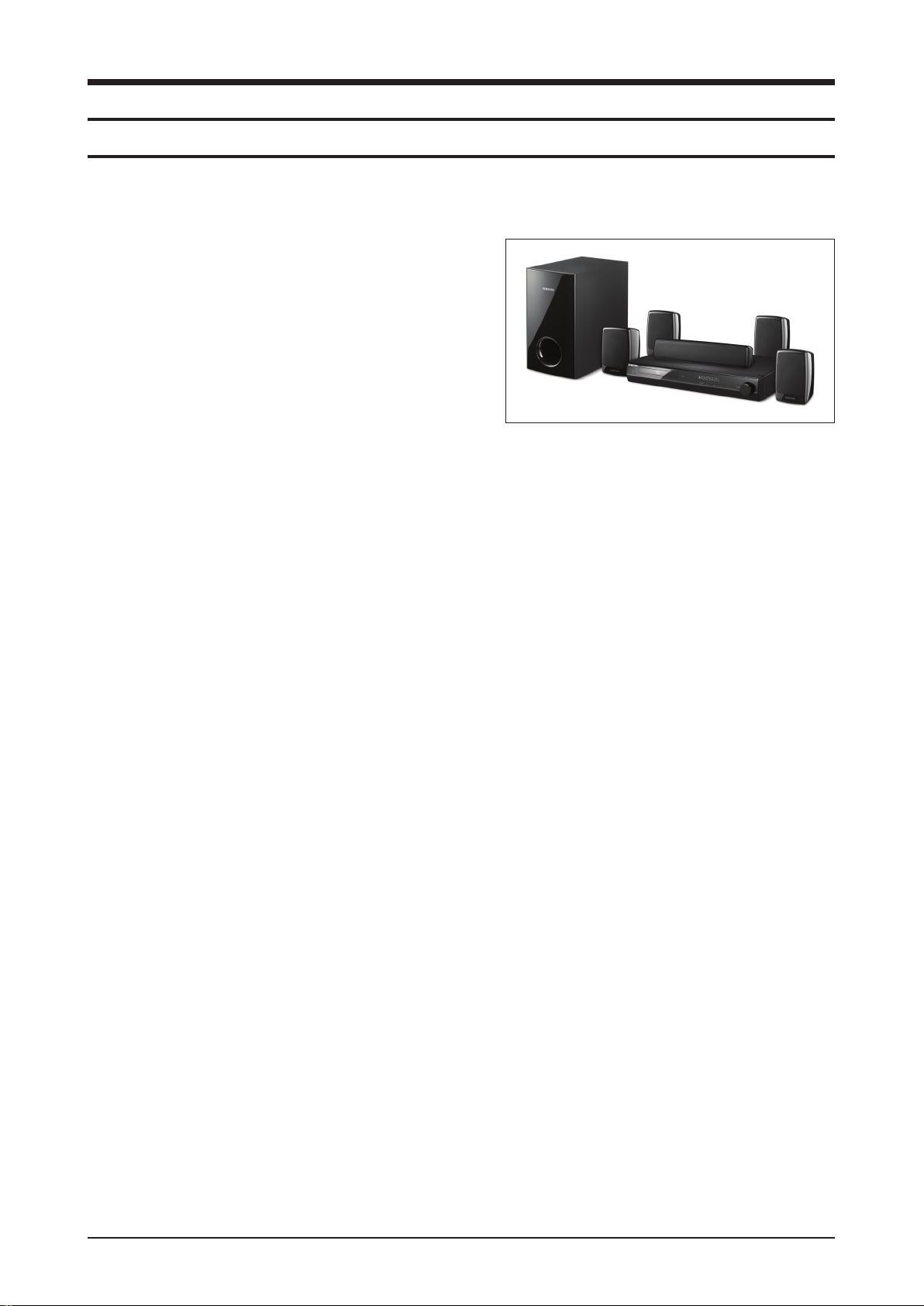
Digital Home Cinema
System
Model Name : HT-Z320 / HT-Z420
Model Code : HT-Z320T/XAA
HT-Z420T/XAA
Speaker PS-Z320 PS-Z420
Front PS-FZ320 PS-FZ420
Center PS-CZ320 PS-CZ420
Rear PS-RZ320 PS-RZ420
Subwoofer PS-WZ320 PS-WZ420
HT-Z320
HT-Z420
This Service Manual is a property of Samsung Electronics
Co.,Ltd. Any unauthorized use of Manual can be punished
under applicable International and/or domestic law.
GSPN (Global Service Partner Network)
Area Web Site
North America service.samsungportal.com
Latin America latin.samsungportal.com
CIS cis.samsungportal.com
Europe europe.samsungportal.com
China china.samsungportal.com
Asia asia.samsungportal.com
Mideast & Africa mea.samsungportal.com
© Samsung Electronics Co.,Ltd.
Apr. 2009
Printed in Korea

Contents
1. Precaution
1-1 Safety Precautions ...........................................................................................1-1
1-2 Servicing Precautions ......................................................................................
1-3
1-3 Precautions for Electrostatically Sensitive Devices (ESDs) .............................
1-4
2. Product Specification
2-1 Product Feature ...............................................................................................2-1
2-2 Specifications ...................................................................................................
2-3
2-3 Specifications Analysis .....................................................................................
2-8
2-4 Accessories ......................................................................................................
2-10
3. Disassembly & Reassembly
3-1 Overall Disassembly & Reassembly ................................................................3-1
4. Troubleshooting
4-1 Checkpoints by Error Mode.............................................................................. 4-2
4-2 Measures to be taken when the Protection Circuit operates ...........................
4-25
4-3 Initialization & Upgrade Methods .....................................................................
4-27
4-4 Buyer-Region Code Setting Method ................................................................
4-30
5. Exploded View & Part List
5-1 HT-Z320T/XAA Exploded View ........................................................................5-2
5-2 HT-Z420T/XAA Exploded View ........................................................................
5-4
5-3 HT-Z320 Speaker System ................................................................................
5-6
5-4 HT-Z420 Speaker System ................................................................................
5-7
5-5 HT-Z320T/XAA Electrical Part List ...................................................................
5-8
5-6 HT-Z420T/XAA Electrical Part List ...................................................................
5-22

Contents
6. PCB Diagram
6-1 Wiring Diagram ................................................................................................6-2
6-2 FRONT PCB Top ..............................................................................................
6-3
6-3 FRONT PCB Bottom ........................................................................................
6-5
6-4 TOUCH PCB Top .............................................................................................
6-6
6-5 TOUCH PCB Bottom ........................................................................................
6-7
6-6 BLUETOOTH PCB Top (US exception) ...........................................................
6-9
6-7 BLUETOOTH PCB Bottom (US exception) ......................................................
6-11
6-8 MAIN PCB Top .................................................................................................
6-12
6-9 MAIN PCB Bottom ...........................................................................................
6-15
6-10 SMPS PCB Top ................................................................................................
6-16
6-11 SMPS PCB Bottom ..........................................................................................
6-18
7. Schematic Diagram
7-1 Overall Block Diagram .....................................................................................7-2
7-2 FRONT .............................................................................................................
7-3
7-3 TOUCH ............................................................................................................
7-4
7-4 BLUETOOTH (US exception) ..........................................................................
7-5
7-5 MPEG
...............................................................................................................7-6
7-6 MICOM .............................................................................................................
7-7
7-7 HDMI ................................................................................................................
7-8
7-8 AV I/O PART .....................................................................................................
7-9
7-9 AMP .................................................................................................................
7-10
7-10 SMPS ...............................................................................................................
7-11
Samsung Electronics 2-1
Product Specification
2. Product Specification
2-1 Product Feature
2-1-1 HT-Z320 Product Feature
1000W Power
HDMI w/ 1080p up-scale
Playability
ASC (Auto Sound Calibration)
DNSe – Power Bass
iPod Dock (US Only)
Wireless Rear
Bluetooth
(The United States Bluetooth exclusion.)
USB Host w/ CD Ripping
KELP Cone Center Speaker
Touch Sensor Button
Variation
• HT-TZ325: 4 Tall Speaker

2-2 Samsung Electronics
Product Specification
2-1-2 HT-Z420 Product Feature
1000W Power
HDMI w/ 1080p up-scale
Playability
ASC (Auto Sound Calibration)
DNSe – Power Bass
iPod Dock (US Only)
Wireless Rear
Bluetooth
(The United States Bluetooth exclusion.)
USB Host w/ CD Ripping
KELP Cone Center, Front Speaker
Touch Sensor Button
Variation
• HT-TZ422: 2 Tall Speaker
Samsung Electronics 2-3
Product Specification
2-2 Specifications
Basic Specification
General
Power Consumption
75 W
Weight 3.5 kg
Dimensions 430 (W) x 70 (H) x 282 (D) mm
Operating Temperature Range
+5°C ~ +35°C
Operating Humidity Range
10 % to 75 %
Disc
DVD (Digital Versatile Disc)
Reading Speed: 3.49 ~ 4.06 m/sec.
Approx. Play Time (Single Sided, Single Layer Disc): 135 min.
CD: 12 cm (COMPACT DISC)
Reading Speed: 4.8 ~ 5.6 m/sec.
Maximum Play Time: 74 min.
CD: 8cm (COMPACT DISC)
Reading Speed: 4.8 ~ 5.6 m/sec.
Maximum Play Time: 20 min.
Video
Output
Composite Video
576i/480i
1 channel: 1.0 Vp-p (75 Ω load)
Component Video
576i/480i
Y: 1.0 Vp-p (75 load)
Pr: 0.70 Vp-p (75 Ω load)
Pb: 0.70 Vp-p (75 Ω load)
Video/
Audio
HDMI OUT
1080p, 1080i, 720p, 576p/480p
HDMI IN
1080p, 1080i, 720p, 576p/480p (If source support it)
Amplifier
Front speaker output
166W x 2 (3Ω)
Center speaker output
166W (3Ω)
Rear speaker output
166W x 2 (3Ω)
Subwoofer speaker output
170W (3Ω)
Frequency range
20Hz ~ 20KHz
S/N Ratio
70dB
Channel separation
60dB
Input sensitivity
(AUX) 400mV

2-4 Samsung Electronics
Product Specification
SWA-4100 Specification (HT-Z420 / TZ422 / TZ425)
Power Consumption 50 W
Weight 1.3 Kg
Dimensions (W x H x D)
76 x 256 x 175 mm
Operating Temperature Range
+5°C ~ +35°C
Operating Humidity Range
10% ~ 75%
Output 166W x 2
Frequency range
20Hz ~ 20KHz
S/N Ratio
75dB
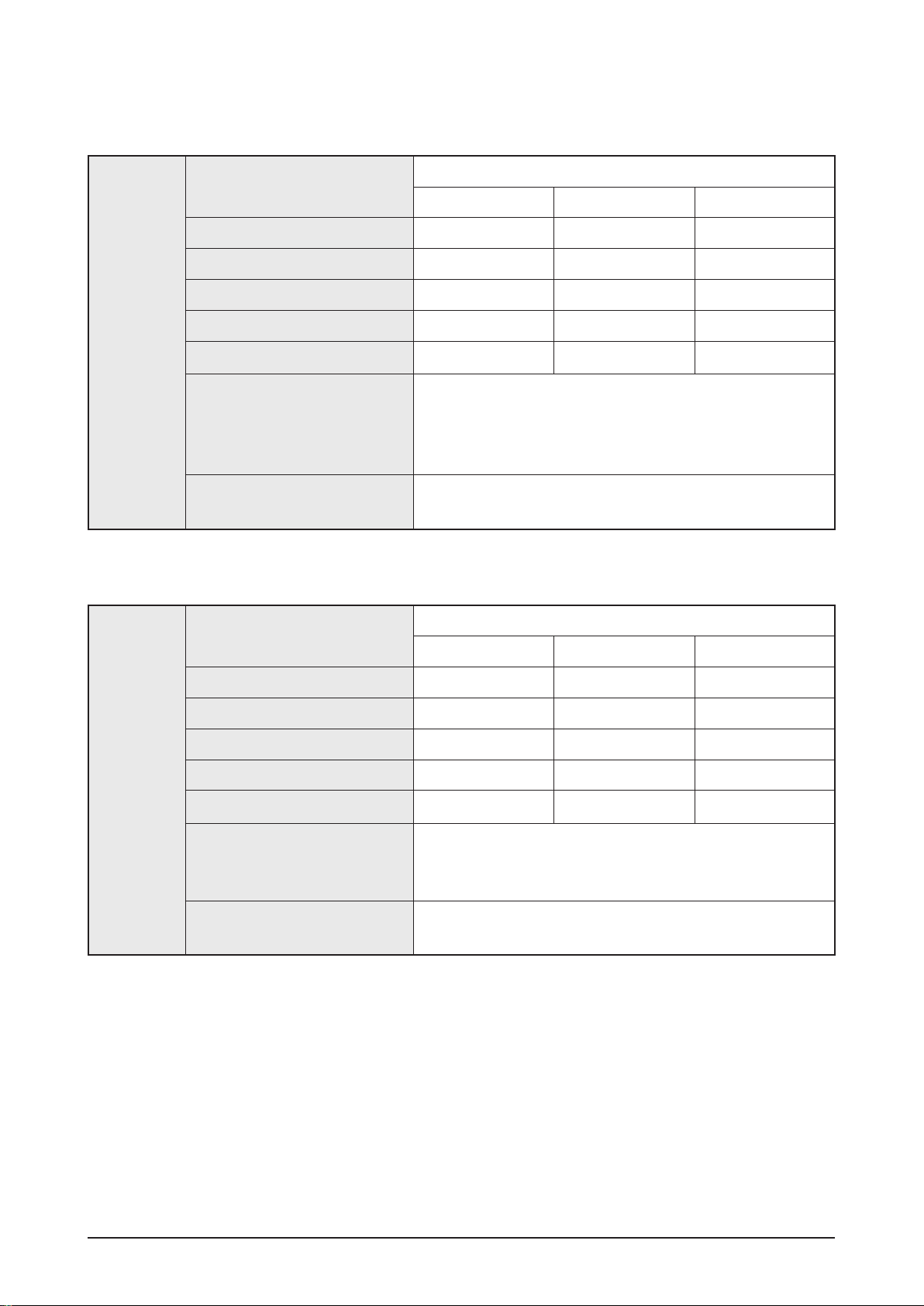
HT-Z320 Speaker Specification
Speaker
Speaker system
5.1ch speaker system
Front/Rear Center Subwoofer
Impedance 3Ω 3Ω 3Ω
Frequency range
140Hz ~ 20KHz 140Hz ~ 20KHz 45Hz ~ 160Hz
Output sound pressure level
86dB/W/M 86dB/W/M 86dB/W/M
Rated input
166W 166W 170W
Maximum input
332W 332W 340W
Dimensions (W x H x D)
Front/Rear: 100 x 150 x 89 mm
Center: 300 x 59 x 50 mm
Subwoofer: 180 x 320 x 380 mm
Weights
Front: 0.5 kg, Center: 0.6 kg
Rear: 0.4 kg, Subwoofer: 4.5 kg
Samsung Electronics 2-5
Product Specification
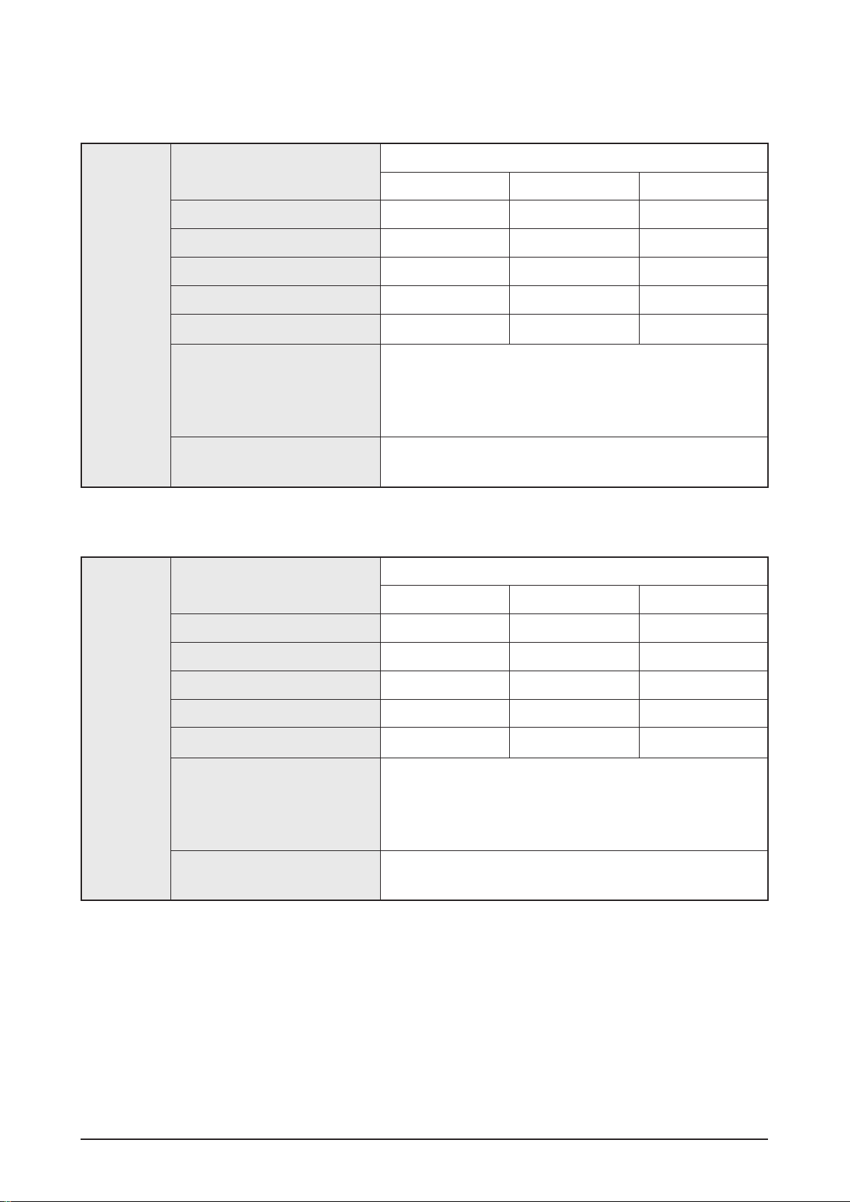
HT-Z322 Speaker Specification
Speaker
Speaker system
5.1ch speaker system
Front/Rear Center Subwoofer
Impedance 3Ω 3Ω 3Ω
Frequency range
140Hz ~ 20KHz 140Hz ~ 20KHz 45Hz ~ 160Hz
Output sound pressure level
86dB/W/M 86dB/W/M 86dB/W/M
Rated input
166W 166W 170W
Maximum input
332W 332W 340W
Dimensions (W x H x D)
Front: 240 x 1020 x 240 mm (Stand Base: 240 x 240)
Rear: 100 x 100 x 93 mm
Center: 300 x 59 x 50 mm
Subwoofer: 180 x 320 x 380 mm
Weights
Front: 2.8 kg, Center: 0.6 kg
Rear: 0.4 kg, Subwoofer: 4.5 kg
HT-Z325 Speaker Specification
Speaker
Speaker system
5.1ch speaker system
Front/Rear Center Subwoofer
Impedance 3Ω 3Ω 3Ω
Frequency range
140Hz ~ 20KHz 140Hz ~ 20KHz 45Hz ~ 160Hz
Output sound pressure level
86dB/W/M 86dB/W/M 86dB/W/M
Rated input
166W 166W 170W
Maximum input
332W 332W 340W
Dimensions (W x H x D)
Front/Rear: 240 x 1026 x 240 mm (Stand Base: 240 x 240)
Center: 300 x 59 x 50 mm
Subwoofer: 180 x 320 x 380 mm
Weights
Front: 2.8 kg, Center: 0.6 kg
Rear: 2.6 kg, Subwoofer: 4.5 kg
2-6 Samsung Electronics
Product Specification
HT-Z420 Speaker Specification
Speaker
Speaker system
5.1ch speaker system
Front/Rear Center Subwoofer
Impedance 3Ω 3Ω 3Ω
Frequency range
140Hz ~ 20KHz 140Hz ~ 20KHz 45Hz ~ 160Hz
Output sound pressure level
86dB/W/M 86dB/W/M 86dB/W/M
Rated input
166W 166W 170W
Maximum input
332W 332W 340W
Dimensions (W x H x D)
Front: 100 x 210 x 99 mm
Rear: 101 x 151 x 88 mm
Center: 300 x 57 x 48 mm
Subwoofer: 180 x 320 x 380 mm
Weights
Front: 0.6 kg, Center: 0.9 kg
Rear: 0.5 kg, Subwoofer: 4.5 kg
HT-Z422 Speaker Specification
Speaker
Speaker system
5.1ch speaker system
Front/Rear Center Subwoofer
Impedance 3Ω 3Ω 3Ω
Frequency range
140Hz ~ 20KHz 140Hz ~ 20KHz 45Hz ~ 160Hz
Output sound pressure level
86dB/W/M 86dB/W/M 86dB/W/M
Rated input
166W 166W 170W
Maximum input
332W 332W 340W
Dimensions (W x H x D)
Front: 260x 1202 x 260 mm (Stand Base: 260 x 260)
Rear: 101 x 151 x 88 mm
Center: 300 x 57 x 48 mm
Subwoofer: 180 x 320 x 380 mm
Weights
Front: 3.0 kg, Center: 0.9 kg
Rear: 0.5 kg, Subwoofer: 4.5 kg
Samsung Electronics 2-7
Product Specification
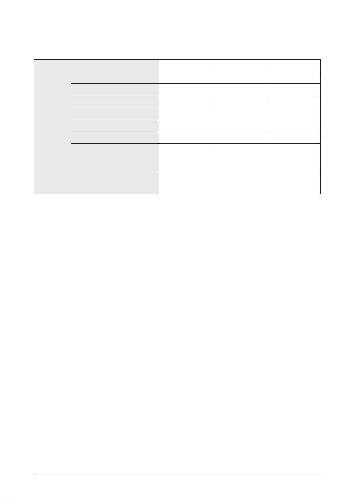
HT-Z425 Speaker Specification
Speaker
Speaker system
5.1ch speaker system
Front/Rear Center Subwoofer
Impedance 3Ω 3Ω 3Ω
Frequency range
140Hz ~ 20KHz 140Hz ~ 20KHz 45Hz ~ 160Hz
Output sound pressure level
86dB/W/M 86dB/W/M 86dB/W/M
Rated input
166W 166W 170W
Maximum input
332W 332W 340W
Dimensions (W x H x D)
Front/Rear: 260 x 1202 x 260 mm (Stand Base: 260 x 260)
Center: 300 x57x 48 mm
Subwoofer: 180 x 320 x 380 mm
Weights
Front: 3.0 kg, Center: 0.9 kg
Rear: 3.0 kg, Subwoofer: 4.5 kg
2-8 Samsung Electronics
Product Specification
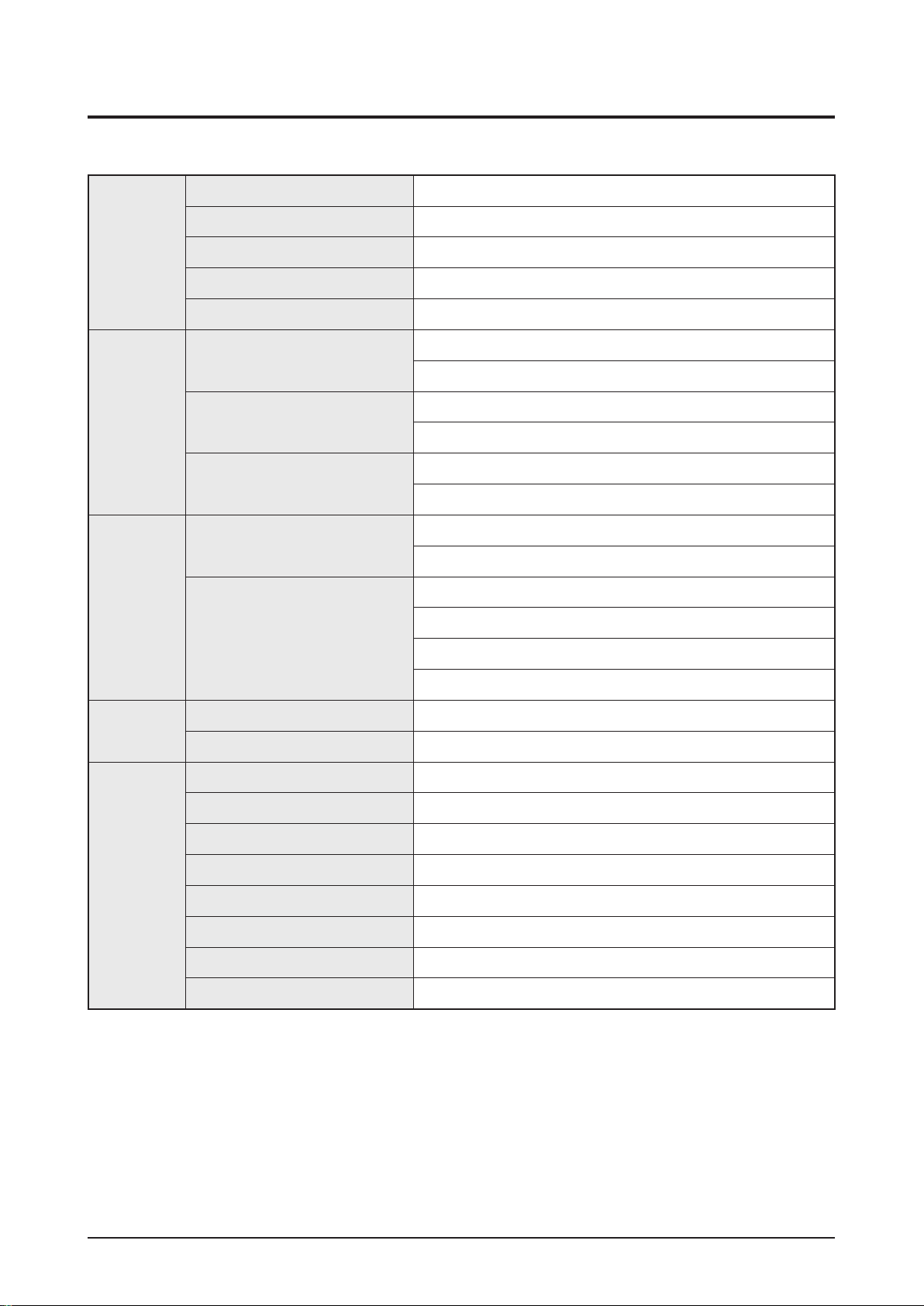
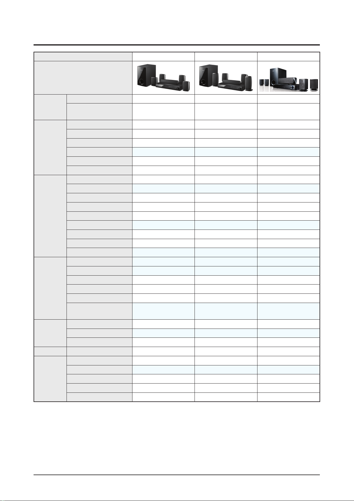
2-3 Specifications Analysis
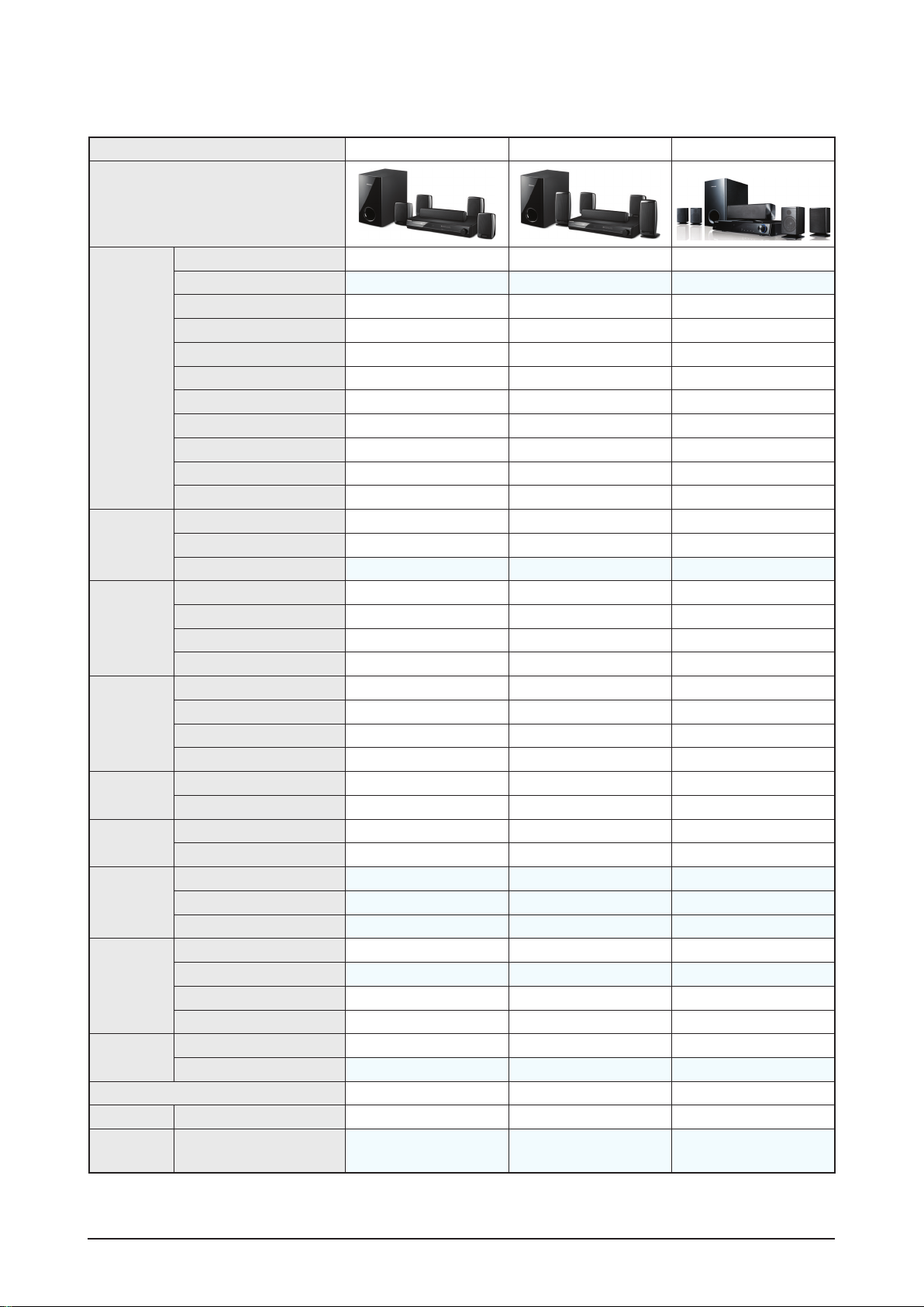
Model Name HT-Z320 HT-Z420 HT-Z310
Photo
Output
Power
RMS (10% THD), REF: 1CH
1000W 1000W 1000W
Output Power (ch)
166W x 5
(Active Subwoofer: 170W)
166W x 5
(Active Subwoofer: 170W)
166W x 5
(Active Subwoofer: 170W)
General
HDMI CEC
Deck 1 1 1
DVD Disc Capacity
1 DVD 1 DVD 1 DVD
Front Display
1Color - VFD X 1Color - VFD
Sleep
Dimmer
Compatible
A/V
CD/CD-R/CD-RW
VCD/SVCD Area specification Area specification X
DVD/DVD-R/DVD-RW
MP3
JPEG Viewer
DVD-OK X X (CIS only) / No Disc&Mic
WMA
DIVX
i-Pod Dock
(US only) (US only) (US, CSA only)
Extra
Features
Wireless Ready
X
Wireless Rear
X
X
Wireless Subwoofer
X X X
Wireless Video
X X X
USB HOST
Bluetooth
X - USA
- Canada
X - USA
- Canada
X
DVD (Video)
Progressive Scan (NT/PAL)
X X X
NTSC ↔ PAL X X (Except USA)
PAL M (Brazil)
Sound Mode
EQ/DSP 3 Mode / 5 Mode 3 Mode / 5 Mode 3 Mode / 5 Mode
DNSe
DNSe 2.1
X X X
ASC
X
Smart Volume
X X X
Audio Upscale
X X X
Power Bass
: application, X: non-application
Samsung Electronics 2-9
Product Specification
Model Name HT-Z320 HT-Z420 HT-Z310
Photo
Audio
Decoding
Dolby Digital
Dolby Digital Plus
X X
Dolby True HD
X X X
Dolby ProLogic-II
Dolby ProLogic-IIx
X X X
Dolby Digital EX
X X X
DTS
DTS-HD (HR/MA)
X X X
DTS ES Discrete 6.1
X X X
DTS 96/24
X X X
DTS Neo 6
X X X
Video Inputs
Component X X X
Composite X X X
HDMI In
X
Video
Outputs
Component
Composite
HDMI Out (CEC)
SCART Out (Only Euro, CIS)
X X X
Audio In/Out
In
AUX1 AUX1 AUX1
Line In
AUX2 AUX2 AUX2
Multi ch Out
X X X
Out X X X
Optical Jack
In (Digital In)
Out X X X
Coaxial Jack
In X X X
Out X X X
Headphone/
MIC Jack
Headphone Jack
X
1 ASC MIC
X
MIC Jack
X X (US only)
Tuner
FM
RDS X X (EU, CIS only)
AM
X X X
Preset Memory
15 15 15
Remote Key
Universal (MBR)
X X X
Key 59 Key 59 Key 58 Key
Dual Voltage
HIGH, LOW, DUAL Voltage HIGH, LOW, DUAL Voltage HIGH, LOW, DUAL Voltage
Speaker Type (Sat/Tallboy) Satellite Satellite Satellite
Net Weight
(Kg)
Set 3.2 3.2 3.6
: application, X: non-application

2-10 Samsung Electronics
Product Specification
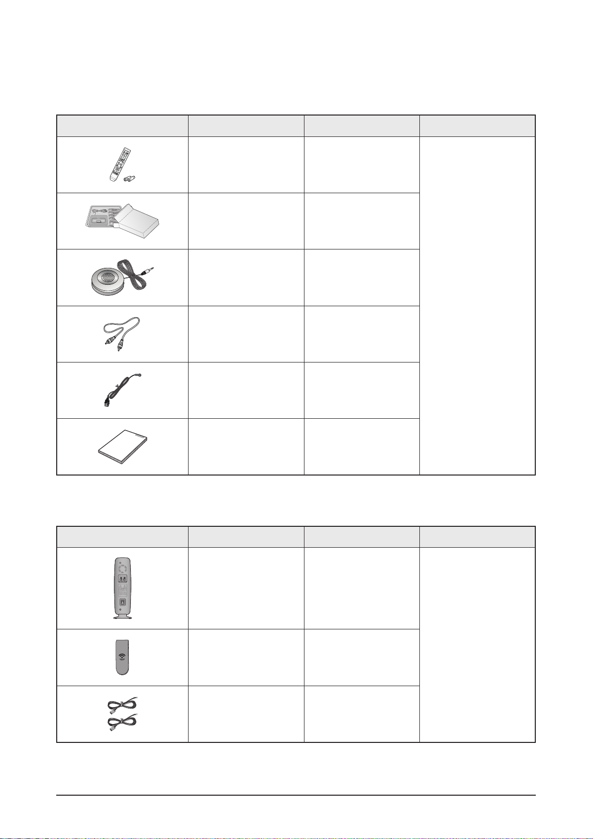
2-4 Accessories
2-4-1 HT-Z320 Supplied Accessories
Accessories Item Item code Remark
Remote Control
Batteries
AH59-02131F
4301-000116
Samsung Service Center
iPod Dock Package AH96-00051A
ASC microphone AH30-00099A
Video Cable AH39-40001V
FM Antenna AH42-00017A
User’s Manual AH68-02166R
Samsung Electronics 2-11
Product Specification
2-4-2 HT-Z420 Supplied Accessories
Accessories Item Item code Remark
Remote Control
Batteries
AH59-02131F
4301-000116
Samsung Service Center
iPod Dock Package AH97-02650C
ASC microphone AH30-00099A
Video Cable AH39-40001V
FM Antenna AH42-00017A
User’s Manual
AH68-02166R
AH68-02168R
SWA-4100 (HT-Z420 / TZ422 / TZ425)
Accessories Item Item code Remark
RESET
Wireless Receiver
Module
AH97-03207A
Samsung Service Center
Tx Card AH40-00149A
Speaker Cable - 2EA AH81-02137A

2-12 Samsung Electronics
MEMO
Samsung Electronics 1-1
Precaution
1. Precaution
Follow these safety, servicing and ESD precautions to prevent damage and protect against potential hazards such
as electrical shock and X-rays.
1-1 Safety Precautions
1. Be sure that all of the built-in protective devices are replaced.
2. When reinstalling the chassis and its assemblies, be sure to restore all protective devices, including control
knobs and compartment covers.
3. Make sure that there are no cabinet openings through which people--particularly children--might insert fingers
and contact dangerous voltages. Such openings include the spacing between the picture tube and the cabinet
mask, excessively wide cabinet ventilation slots, and improperly fitted back covers.
4. Design Alteration Warning:
Never alter or add to the mechanical or electrical design of the unit.
Example: Do not add auxiliary audio or video connectors. Such alterations might create a safety hazard.
Also, any design changes or additions will void the manufacturer’s warranty.
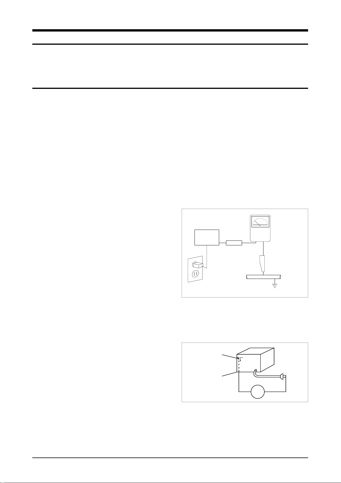
5. Leakage Current Hot Check (Fig. 1-1):
Warning: Do not use an isolation transformer during this
test. Use a leakage-current tester or a metering system
that complies with American National Standards Institute
(ANSI C101.1, Leakage Current for Appliances), and
Underwriters Laboratories (UL Publication UL1410,
59.7).
With the unit completely reassembled, plug the AC line
cord directly into a 120V AC outlet. With the unit’s AC
switch first in the ON position and then OFF, measure
the current between a known earth ground (metal water
pipe, etc.) and all exposed metal parts. Examples:
Handle brackets, metal cabinets, screwheads and control shafts. The current measured should not exceed 0.5
milliamp. Reverse the powerplug prongs in the AC outlet and repeat.
6. Insulation Resistance Cold Check:
(1) With the unit’s AC plug disconnected from the AC
source, connect an electrical jumper across the two AC
prongs. (2) Set the power switch to ON. (3) Measure
the resistance between the shorted AC plug and any
exposed metallic parts.
Example: Screwheads, antenna, control shafts or handle
brackets.
If any of the exposed metallic parts has a return path
to the chassis, the measured resistance should be between 1 and 5.2 megohms. If there is no return path, the
measured resistance should be “infinite.” If the resistance is outside these limits, a shock hazard might exist.
See Fig. 1-2
DEVICE
UNDER
TEST
LEAKAGE
CURRENT
TESTER
TEST ALL
EXPOSED METAL
SURFACES
2-WIRE CORD
ALSO TEST WITH
PLUG REVERSED
(USING AC
ADAPTER PLUG
AS REQUIRED)
EARTH
GROUND
(READING
SHOULD NOT BE
ABOVE 0.5mA)
<Fig. 1-1 AC Leakage Test>
Antenna
Terminal
ohm
<Fig. 1-2 Insulation Resistance Test>
Exposed
Metal Part
Ohmmeter

1-2 Samsung Electronics
Precaution
7. Components, parts and wiring that appear to have overheated or that are otherwise damaged should be
replaced with parts that meet the original specifications. Always determine the cause of damage or overheating,
and correct any potential hazards
8. Observe the original lead dress, especially near the following areas: Antenna wiring, sharp edges, and
especially the AC and high voltage power supplies. Always inspect for pinched, out-of-place, or frayed wiring.
Do not change the spacing between components and the printed circuit board. Check the AC power cord for
damage. Make sure that no wires or components touch thermally hot parts.
9. Product Safety Notice:
Some electrical and mechanical parts have special safety-related characteristics which might not be obvious
from visual inspection. These safety features and the protection they give might be lost if the replacement
component differs from the original--even if the replacement is rated for higher voltage, wattage, etc.
10. Components that are critical for safety are indicated in the circuit diagram by shading,
or . Use
replacement components that have the same ratings, especially for flame resistance and dielectric strength
specifications. A replacement part that does not have the same safety characteristics as the original might
create shock, fire or other hazards.
Samsung Electronics 1-3
Precaution
1-2 Servicing Precautions
1. Servicing precautions are printed on the cabinet. Follow them.
2. Always unplug the unit’s AC power cord from the AC power source before attempting to: (a) Remove or reinstall
any component or assembly, (b) Disconnect an electrical plug or connector, (c) Connect a test component in
parallel with an electrolytic capacitor.
3. Some components are raised above the printed circuit board for safety. An insulation tube or tape is sometimes
used. The internal wiring may be clamped to prevent contact with thermally hot components. Reinstall all such
elements to their original position.
4. After servicing, always check that the screws, components and wiring have been correctly reinstalled.
Make sure that the portion around the serviced part has not been damaged.
5. Check the insulation between the blades of the AC plug and accessible conductive parts (examples: metal
panels, input terminals and earphone jacks).
6. Insulation Checking Procedure: Disconnect the power cord from the AC source and turn the power switch ON.
Connect an insulation resistance meter (500V) to the blades of the AC plug.
The insulation resistance between each blade of the AC plug and accessible conductive parts (see above)
should be greater than 1 megohm.
7. Never defeat any of the B+ voltage interlocks. Do not apply AC power to the unit (or any of its assemblies)
unless all solid-state heat sinks are correctly installed.
8. Always connect a test instrument’s ground lead to the instrument chassis ground before connecting the positive
lead; always remove the instrument’s ground lead last.
First read the “Safety Precautions” section of this manual. If some unforeseen circumstance
creates a conflict between the servicing and safety precautions, always follow the safety
precautions.

1-4 Samsung Electronics
Precaution
1-3 Precautions for Electrostatically Sensitive Devices (ESDs)
1. Some semiconductor (“solid state”) devices are easily damaged by static electricity.
Such components are called Electrostatically Sensitive Devices (ESDs). Examples include integrated circuits
and some field-effect transistors. The following techniques will reduce the occurrence of component damage
caused by static electricity.
2. Immediately before handling any semiconductor components or assemblies, drain the electrostatic charge from
your body by touching a known earth ground. Alternatively, wear a discharging wrist-strap device. (Be sure to
remove it prior to applying power--this is an electric shock precaution.)
3. After removing an ESD-equipped assembly, place it on a conductive surface such as aluminum foil to prevent
accumulation of electrostatic charge.
4. Do not use freon-propelled chemicals. These can generate electrical charges that damage ESDs.
5. Use only a grounded-tip soldering iron when soldering or unsoldering ESDs.
6. Use only an anti-static solder removal device. Many solder removal devices are not rated as “anti-static” (these
can accumulate sufficient electrical charge to damage ESDs).
7. Do not remove a replacement ESD from its protective package until you are ready to install it.
Most replacement ESDs are packaged with leads that are electrically shorted together by conductive foam,
aluminum foil or other conductive materials.
8. Immediately before removing the protective material from the leads of a replacement ESD, touch the protective
material to the chassis or circuit assembly into which the device will be installed.
9. Minimize body motions when handing unpackaged replacement ESDs. Motions such as brushing clothes
together, or lifting a foot from a carpeted floor can generate enough static electricity to damage an ESD.
Samsung Electronics 3-1
Disassembly & Reassembly
3. Disassembly & Reassembly
3-1 Overall Disassembly & Reassembly
- Be careful to follow the disassembly sequence described in the manual. Otherwise, the product
may be damaged.
- Be sure to carefully read and understand the safety instructions before performing any work as
the IC chips on the PCB are vulnerable to static electricity.
- Assemble in the reverse order of disassembly.
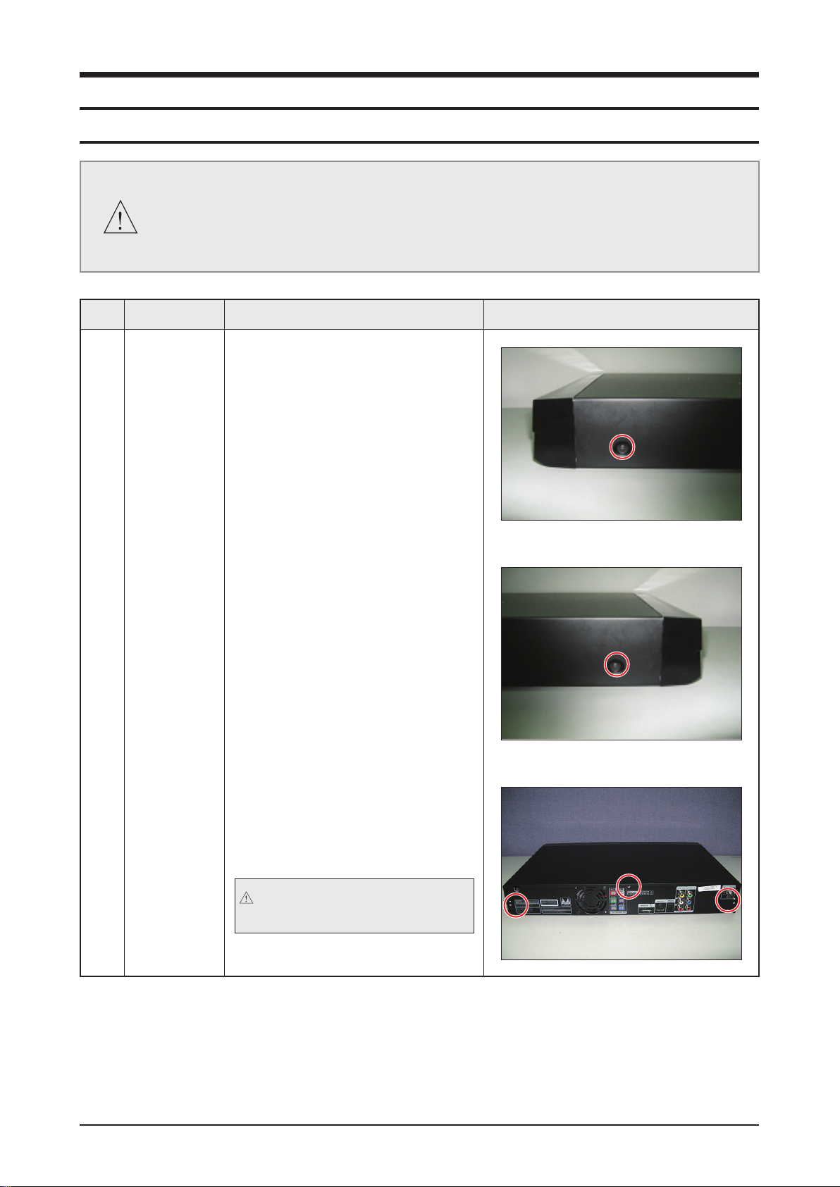
No. Part Name Description Description Photo
1 COVER-TOP 1) Unscrew the 2 screws from the Left
and Right Side.
: TAP TITE SCREW BH 3*10 BLACK
2) Unscrew the 3 screws from the Rear.
: TAP TITE SCREW BH 3*10 BLACK
3) Lift the Top-Cover to separate it.
Be careful not to make any
scratches as you remove it.
<Right-Side>
<Left-Side>
3-2 Samsung Electronics
Disassembly & Reassembly
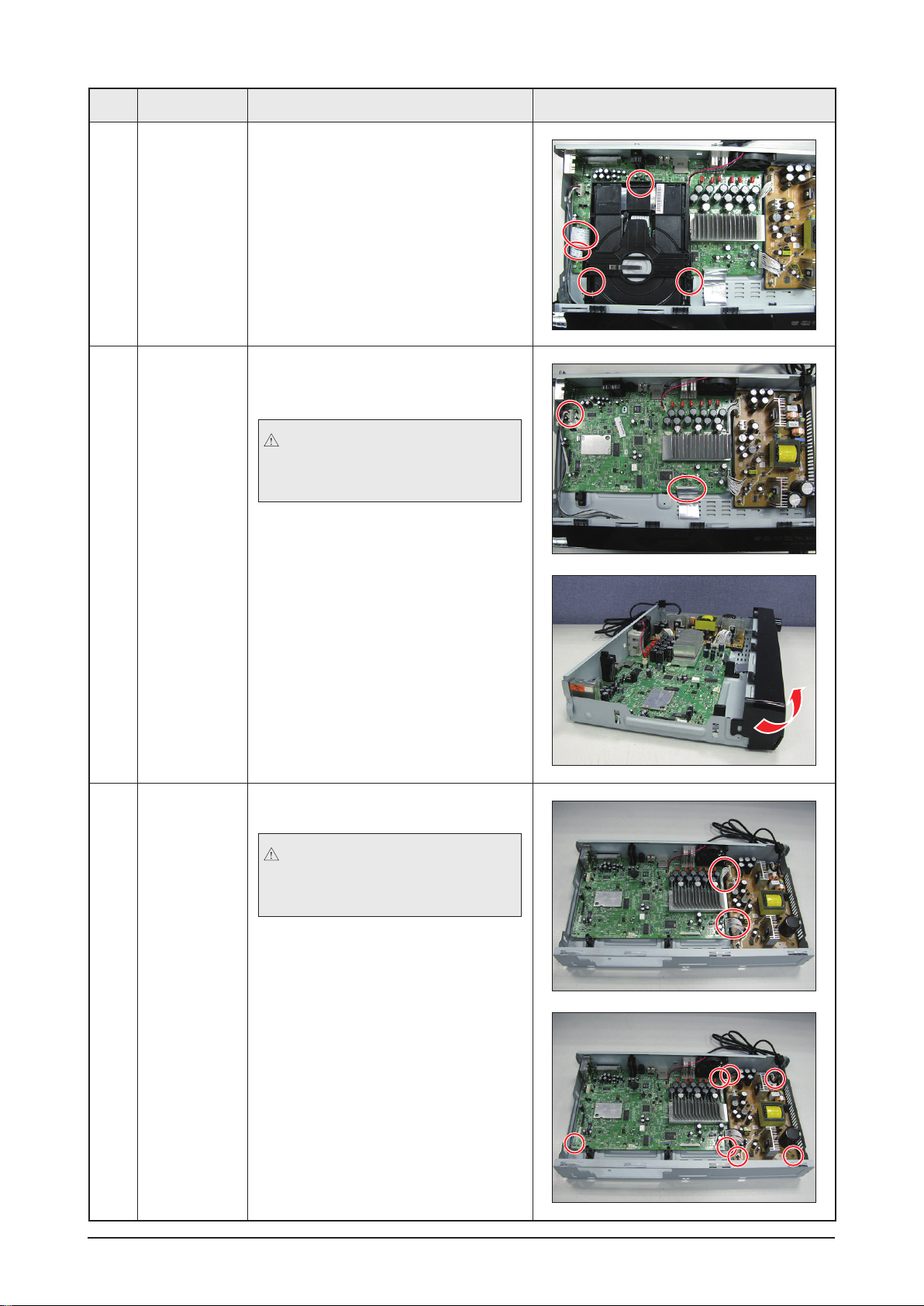
No. Part Name Description Description Photo
2 DECK 1) Remove the DECK.
Remove the 3 screws and wire.
: TAP TITE SCREW BH 3*25 SILVER
3
CABINET
FRONT
1) Remove the wires connected to the
CABINET FRONT.
In case of pulling up the PCB
cable, it is easier to pull up when
pressing the grip.
2) Lift and pull out the CABINET
FRONT.
4 PCB 1) Remove the wires between PCB.
In case of pulling up the PCB
cable, it is easier to pull up when
pressing the grip.
2) Remove the 7 screws on the PCB.
: TAP TITE SCREW BH 3*6 SILVER
Samsung Electronics 3-3
Disassembly & Reassembly
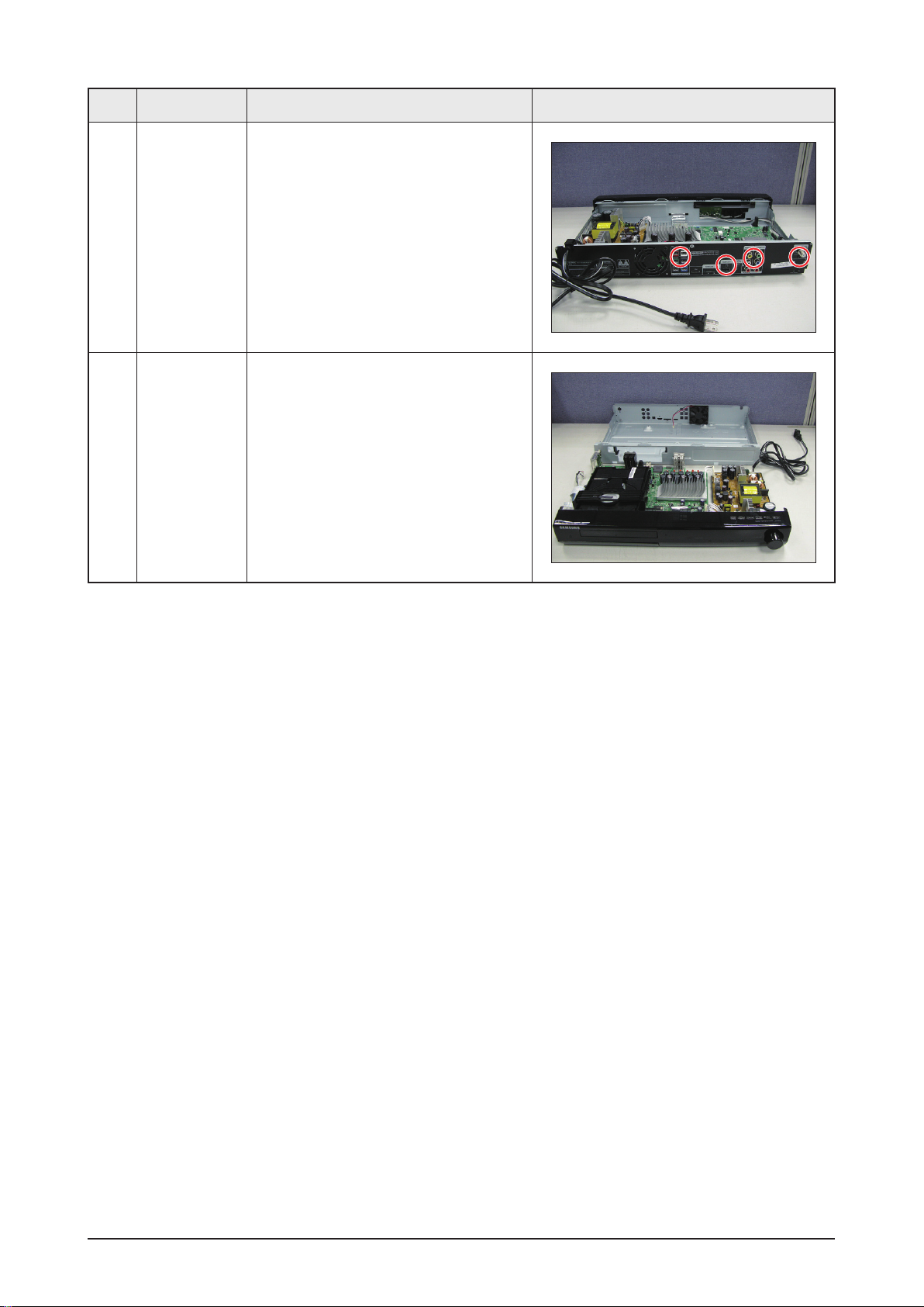
No. Part Name Description Description Photo
5
CABINET-
BOTTOM
REAR
1) Remove the remaining 4 screws in
the CABINET-BOTTOM REAR.
: TAP TITE SCREW BH 3*10 BLACK
6 SET 1) Picture of a disassembled product.

3-4 Samsung Electronics
MEMO

Samsung Electronics 4-1
Troubleshooting
4. Troubleshooting
4-1 Checkpoints by Error Mode ................................................................4-2
4-2 Measures to be taken when the Protection Circuit operates ...........
4-25
4-3 Initialization & Upgrade Methods ........................................................
4-27
4-4 Buyer-Region Code Setting Method ...................................................
4-30
4-2 Samsung Electronics
Troubleshooting
4-1 Checkpoints by Error Mode
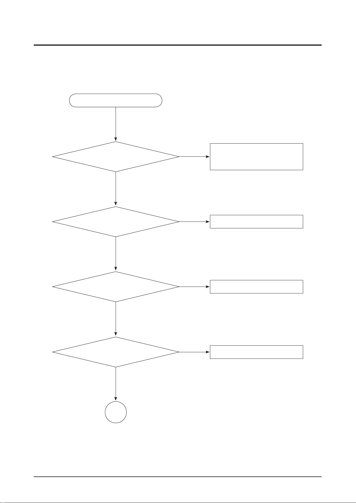
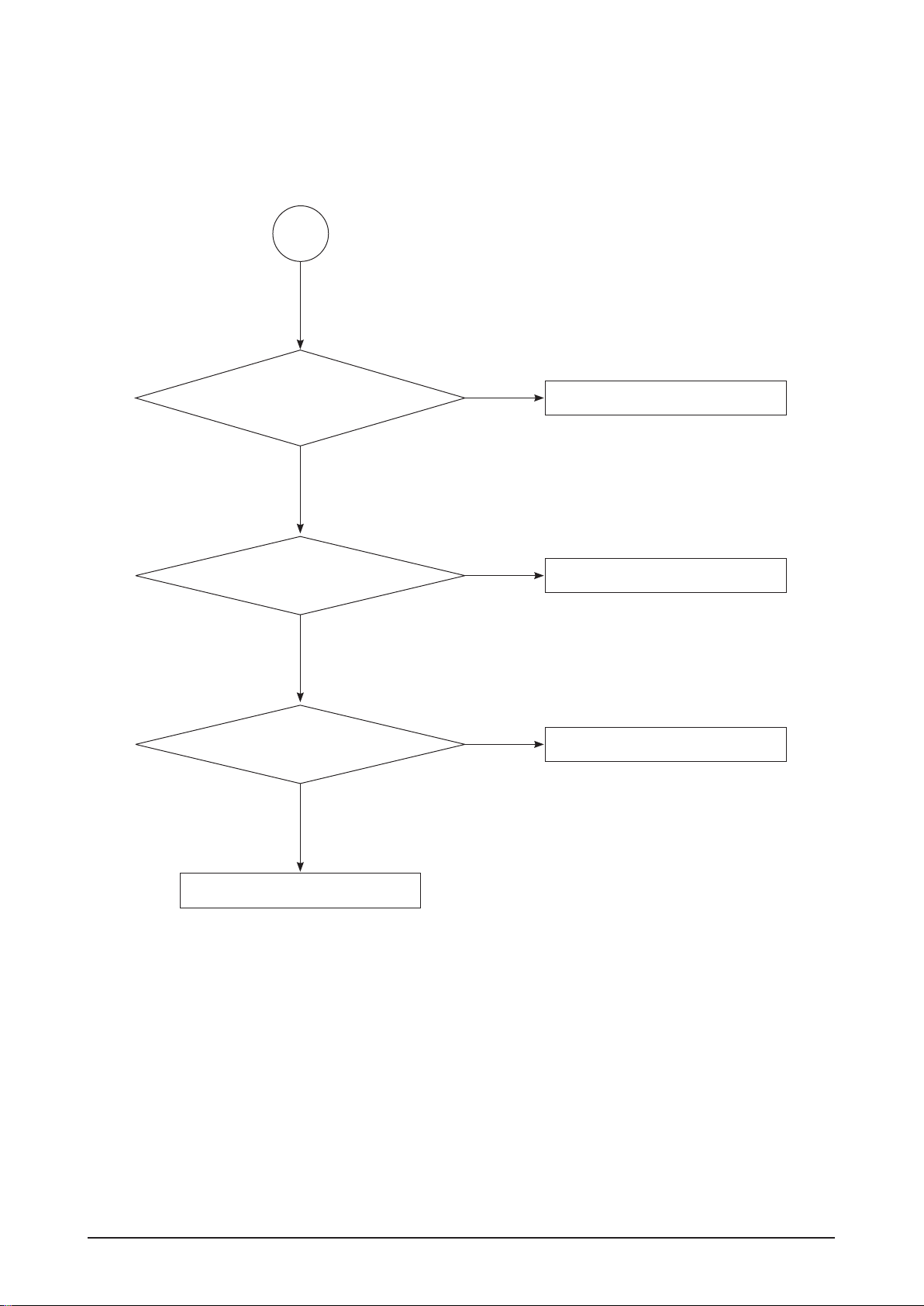
4-1-1 Power Failure
5.8V output check
(COM3, Pin 1, 2) → 5.8V?
No
The power does not turn on.
Check Main Assy
- specially check around MICOM IC
(Vcc)
Yes
Replace IC5601
No
Check diodes (DR5601, DR3502)
→ OK?
Replace Diode
No
Yes
Check input voltage of IC5601
kathode of DR5601 → 6 ~ 16V?
Check primary side.
Fuse (F1) → OK?
Replace Fuse (6.3A 250V)
No
Yes
Yes
A
Samsung Electronics 4-3
Troubleshooting
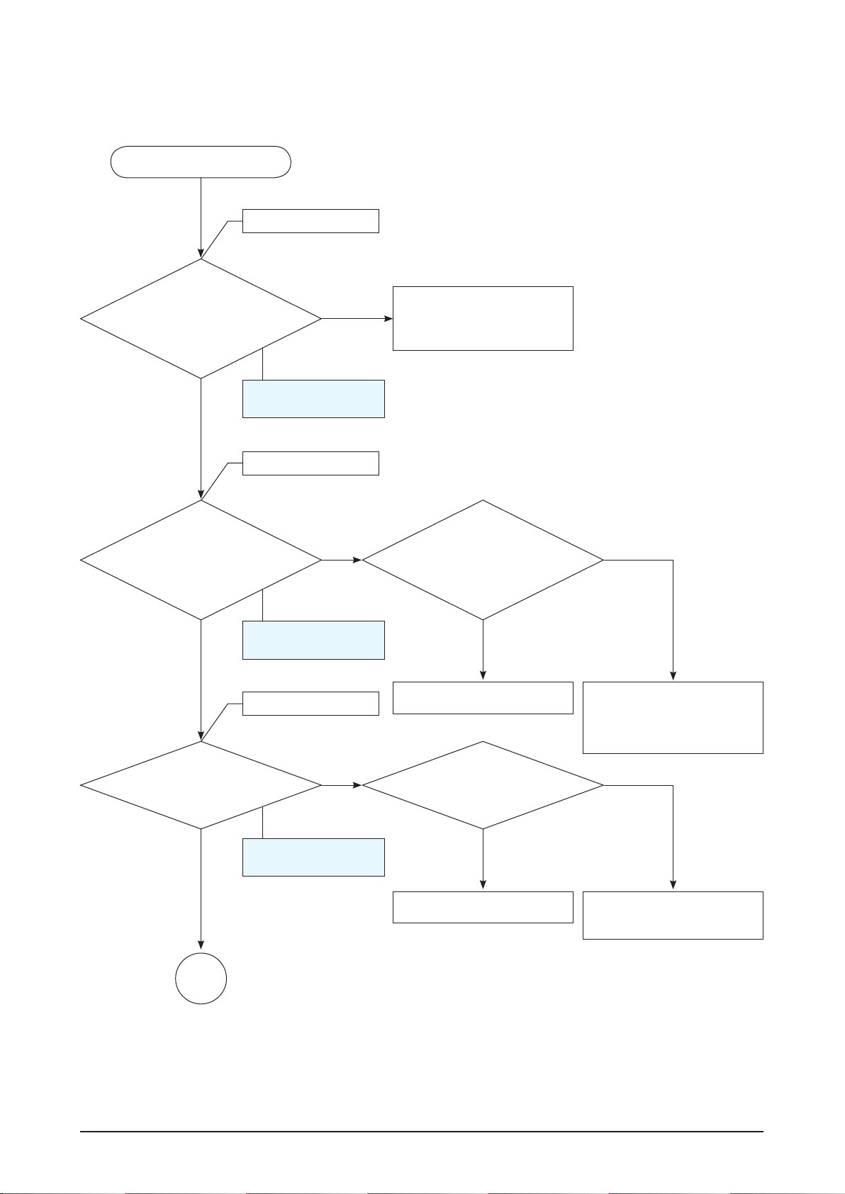
No
Replace IC01
Yes
Replace M01
No
Check components around IC.
R13, R14, D06, D07, D05
Replace component if it has problem.
No
Yes
Check M01.
All pins are not shorted to each other.
Replace SMPS ASSY
Yes
Check SWITCHING IC (IC01)
short test pin 8 to pin 1, 2, 3, 4, 5, 6, 7 → OK
(means not short)?
A
4-4 Samsung Electronics
Troubleshooting
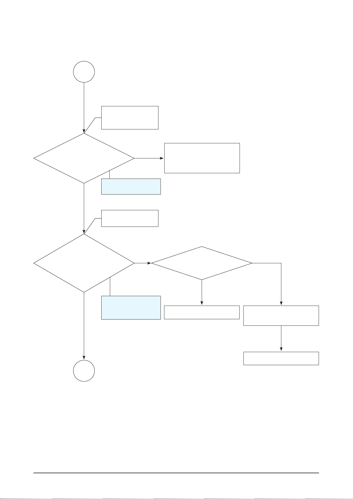
4-1-2 No Sound (waveform when 1KHz, -20dB signal is input)
Refer to wave pattern
image of Fig. 4-1.
AIC1 CS5345
AUX1: pin 21, 22
AUX2: pin 7, 8
TUNER: pin 11, 12
IPOD: pin 26, 27
Yes
AIC1 CS5345
pin 41: SDOUT
pin 42: SCLK
pin 43: LRCLK
pin 44: MCLK
Check if the
D5V of LOADSW is measured
at the pin of 7, 8 and check if the 3.3V
of DDC1 is measured at the
pin of 7, 8.
Replace the DDC1.
Check the audio input of each
component including connector
connectivity.
Check if the pin 5 and 6 of
CON3 of SMPS are 12V.
Check if the pin 1, 2 of CON3
is 5V.
No
No
No
No Sound
Yes
Yes
B
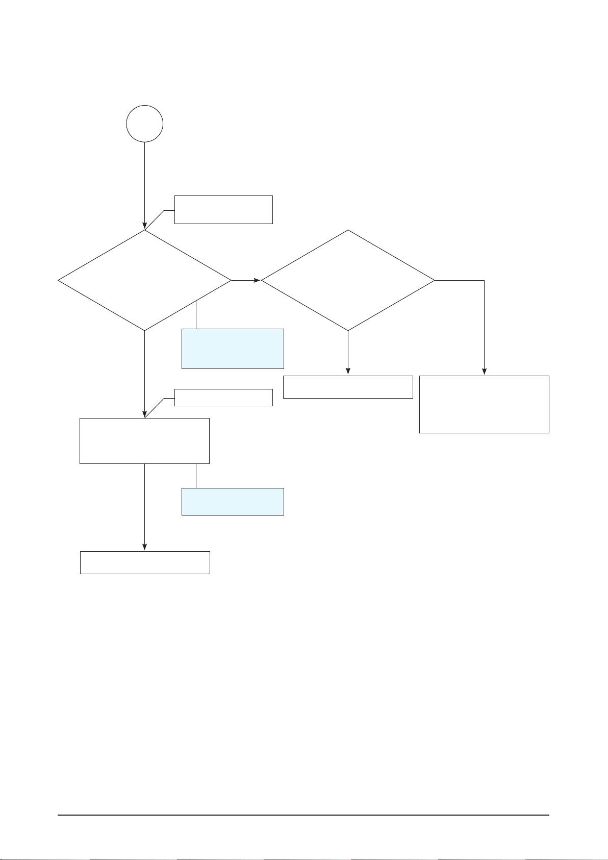
Check the outputs of the pin 65,
66, 67 of MIC1 (ES8391).
Check the VD33 and
VDD1.2 is measured at the pin 62,
77, 79 of MIC1.
Replace of the MIC1.
Check if the pin 7 and 8 of
DDC1 ic are 3.3V.
No
No
Yes
Yes
Check ADC input.
Check ADC output.
Check MPEG input.
Refer to wave pattern
image of Fig. 4-1.
Refer to wave pattern
image of Fig. 4-2.
Samsung Electronics 4-5
Troubleshooting
Yes
Check the pattern or Parts
between MIC1 and PWMIC1.
(ex: soldering mistake, parts
missed)
No
Check the singnal
output is measured at
pin 11, 12, 15, 16, 17, 18 of
PWMIC1 (PS9829B).
Check MPEG output
and connecor
connectivity.
B
C
Check if the
outputs of the pin 48, 49, 51,
52, 54, 55, 58, 59, 61, 62, 67, 68, 70,
71, 74, 75 of PWMIC1 PS9829B
of the MAIN PCB
are measured.
Check if
the VDD 3.3V of PWMIC1
is measured at of the pin 4,
10, 22, 29.
Replace the PWMIC1.
Check if the pin 7 and 8 of
DDC1 is 3.3V.
No
No
Yes
Yes
Check the PWM
output.
Refer to wave pattern
image of Fig. 4-4-1
and Fig. 4-4-2.
Refer to wave pattern
image of Fig. 4-3.
Replace the DDC1 IC.
4-6 Samsung Electronics
Troubleshooting
C
Replace the SPK1 connectors.
Check the SPK output.
Check if the outputs
of the pin 28, 31, 36 and 39 of
IC1CW, IC1L and IC1R of the TAS5352
of the MAIN PCB are
measured.
Replace the TAS5352.
Check if the GVDD of pin 1 of
J3 is 12V.
Check if the PVDD of pin 7, 8,
9 of J3 are 35V.
No
Yes
Check if GVDD
of TAS5352 is measured at
the pin 1, 22, 23. Check if PVDD of
TAS5352 is measured at the
pin 26, 27, 32, 35, 40,
41.
Yes
No
Check if the outputs of the
SPK1 of AMP PCB are
measured.
Refer to wave pattern
image of Fig. 4-5.
Refer to wave pattern
image of Fig. 4-4-1
and Fig. 4-4-2.
Check the AMP IC
output.
 Loading...