


OPERATOR'S MANUAL
10 in. (254 mm) TABLE SAW BTS15
Your new Table Saw has been engineered and manufactured to Ryobi's high standards for dependability, ease of operation, and operator safety. Properly cared for, it will give you years of rugged, trouble-free performance.
WARNING: To reduce the risk of injury, the user must read and understand the operator's manual before using this product.
Thank you for buying a Ryobi Table Saw.
SAVE THIS MANUAL FOR FUTURE REFERENCE

TABLE OF CONTENTS
Rules for Safe Operation ........................................ |
3-6 |
Electrical ..................................................................... |
7 |
Glossary of Terms ...................................................... |
8 |
Unpacking and Tools Needed ................................... |
9 |
Loose Parts List .................................................. |
10-11 |
Features ............................................................... |
12-14 |
Operating Components .............................................. |
13 |
Power Switch ............................................................. |
13 |
To Turn Your Saw On ................................................ |
13 |
To Turn Your Saw Off ................................................ |
13 |
To Lock Your Saw ...................................................... |
13 |
Blades ........................................................................ |
14 |
Product Specifications ................................................ |
14 |
Assembly ............................................................. |
15-17 |
Assembling Leg Stand ............................................... |
15 |
Assembling Storage Brackets .................................... |
15 |
To Install Rip Fence ................................................... |
16 |
To Install Miter Table .................................................. |
16 |
To Lock Miter Fence .................................................. |
16 |
Blade and Guard Assembly |
|
To Check Saw Blade Installation ........................... |
17 |
To Install Blade Guard Assembly .......................... |
17 |
Operation ............................................................. |
18-26 |
Basic Operation .......................................................... |
18 |
Causes of Kickback and Avoiding Kickback .............. |
18 |
Cutting Aids ................................................................ |
18 |
Featherboard |
|
How to Make a Featherboard ................................ |
19 |
How to Mount a Featherboard ............................... |
19 |
Types of Cuts ............................................................. |
20 |
To Adjust the Blade Depth ......................................... |
21 |
To Adjust the Blade Angle .......................................... |
21 |
To Set the Scale to the Blade .................................... |
21 |
To Use the Outfeed Support ...................................... |
22 |
To Use the Solid Table Extension .............................. |
22 |
Making Cuts .......................................................... |
21-26 |
To Make a Cross Cut ............................................ |
22 |
To Make a Miter Cut .............................................. |
23 |
To Make a Straight Rip Cut ................................... |
23 |
To Make a Bevel Cross Cut .................................. |
24 |
To Make a Bevel Rip Cut ...................................... |
24 |
To Make a Compound Miter Cut ........................... |
25 |
To Make Non-Through Cuts .................................. |
25 |
To Make Dado Cuts .............................................. |
26 |
Adjustments ........................................................ |
27-34 |
Removing/Replacing the Throat Plate ....................... |
27 |
To Check the Alignment of the Rip Fence |
|
to the Blade ........................................................... |
27 |
To Remove the Blade ................................................ |
28 |
Aligning Spreader with the Blade ............................... |
29 |
To Set Blade at 0° or 45° ............................................. |
30 |
To Adjust Sliding Miter Table Assembly ................ |
31-34 |
Maintenance ............................................................. |
35 |
General Maintenance ................................................. |
35 |
Lubrication .................................................................. |
35 |
Tilt/Elevating Mechanism ........................................... |
35 |
Blade and Blade Wrench Storage .............................. |
35 |
Miter Fence and Rip Fence Storage .......................... |
35 |
Troubleshooting ....................................................... |
36 |
Parts Ordering / Service .......................................... |
38 |
Page 2
RULES FOR SAFE OPERATION
The purpose of safety symbols is to attract your attention to possible dangers. The safety symbols, and the explanations with them, deserve your careful attention and understanding. The safety warnings do not by themselves eliminate any danger. The instructions or warnings they give are not substitutes for proper accident prevention measures.
Symbol Meaning
DANGER: Indicates an imminently hazardous situation which, if not avoided, will result in death or serious injury.
WARNING: Indicates a potentially hazardous situation which, if not avoided, could result in serious injury.
CAUTION: Indicates a potentially hazardous situation which, if not avoided, may result in minor or moderate injury. It may also be used to alert against unsafe practices that may cause property damage.
NOTE: Advises you of information or instructions vital to the operation or maintenance of the equipment.
IMPORTANT
Servicing requires extreme care and knowledge and should be performed only by a qualified service technician. For service we suggest you return the tool to your nearest Ryobi
AUTHORIZED SERVICE CENTER for repair. When servicing, use only identical Ryobi replacement parts.
 WARNING:
Observe all normal safety precautions related to avoiding electrical shock.
WARNING:
WARNING:
Do not attempt to use the tool until you read thoroughly and understand completely the operator’s manual. Pay close attention to the safety rules, including Dangers, Warnings, and Cautions. If you use this tool properly and only for what it is intended, you will enjoy years of safe, reliable service.
The operation of any power tool can result in foreign objects being thrown into your eyes, which can result in severe eye damage. Before beginning tool operation, always wear safety goggles or safety glasses with side shields and a full face shield when needed. We recommend Wide Vision Safety Mask for use over eyeglasses or standard safety glasses with side shields. Always wear eye protection which is marked to comply with ANSI Z87.1.
Look for this symbol to point out important safety precautions. It means attention!!! Your safety is involved.
Page 3

RULES FOR SAFE OPERATION
Safe operation of this power tool requires that you read and understand this operator's manual and all labels affixed to the tool. Safety is a combination of common sense, staying alert, and knowing how your table saw works.
READ ALL INSTRUCTIONS
KNOW YOUR POWER TOOL. Read the operator's manual carefully. Learn the saw's applications and limitations as well as the specific potential hazards related to this tool.
GUARD AGAINST ELECTRICAL SHOCK BY PREVENTING BODY CONTACT WITH GROUNDED SURFACES. For example; pipes, radiators, ranges, refrigerator enclosures.
KEEP GUARDS IN PLACE and in working order. Never operate the tool with any guard or cover removed. Make sure all guards are operating properly before each use.
REMOVE ADJUSTING KEYS AND WRENCHES. Form habit of checking to see that keys and adjusting wrenches are removed from tool before turning it on.
KEEP WORK AREA CLEAN. Cluttered areas and benches invite accidents. DO NOT leave tools or pieces of wood on the saw while it is in operation.
AVOID DANGEROUS ENVIRONMENT. Don't use power tools in damp or wet locations or expose to rain. Keep work area well lit.
KEEP CHILDREN AND VISITORS AWAY. All visitors should wear safety glasses and be kept a safe distance from work area. Do not let visitors contact tool or extension cord while operating.
MAKE WORKSHOP CHILDPROOF with padlocks or master switches, or by removing starter keys.
DON'T FORCE TOOL. It will do the job better and safer at the feed rate for which it was designed.
USE RIGHT TOOL. Don't force tool or attachment to do a job it was not designed for. Don't use it for a purpose not intended.
MAKE SURE YOUR EXTENSION CORD IS IN GOOD CONDITION. When using an extension cord, be sure to use one heavy enough to carry the current your product will draw. An undersized cord will cause a drop in line voltage resulting in loss of power and overheating. A wire gage size (A.W.G.) of at least 14 is recommended for an extension cord 25 feet or less in length. If in doubt, use the next heavier gage. The smaller the gage number, the heavier the cord.
DRESS PROPERLY. Do not wear loose clothing, gloves, neckties, or jewelry. They can get caught and draw you into moving parts. Rubber gloves and nonskid footwear are recommended when working outdoors. Also wear protective hair covering to contain long hair.
ALWAYS WEAR SAFETY GLASSES WITH SIDE SHIELDS. Everyday eyeglasses have only impactresistant lenses; they are NOT safety glasses.
SECURE WORK. Use clamps or a vise to hold work when practical. It's safer than using your hand and frees both hands to operate tool.
DON'T OVERREACH. Keep proper footing and balance at all times.
MAINTAIN TOOLS WITH CARE. Keep tools sharp and clean for better and safer performance. Follow instructions for lubricating and changing accessories.
DISCONNECT TOOLS. When not in use, before servicing, or when changing attachments, blades, bits, cutters, etc., all tools should be disconnected.
AVOID ACCIDENTAL STARTING. Be sure switch is off when plugging in.
USE RECOMMENDED ACCESSORIES. The use of improper accessories may cause risk of injury.
NEVER STAND ON TOOL. Serious injury could occur if the tool is tipped or if the cutting tool is unintentionally contacted.
CHECK DAMAGED PARTS. Before further use of the tool, a guard or other part that is damaged should be carefully checked to determine that it will operate properly and perform its intended function. Check for alignment of moving parts, binding of moving parts, breakage of parts, mounting and any other conditions that may affect its operation. A guard or other part that is damaged must be properly repaired or replaced by an authorized service center to avoid risk of personal injury.
USE THE RIGHT DIRECTION OF FEED. Feed work into a blade or cutter against the direction of rotation of blade or cutter only.
NEVER LEAVE TOOL RUNNING UNATTENDED. TURN POWER OFF. Don't leave tool until it comes to a complete stop.
PROTECT YOUR LUNGS. Wear a face or dust mask if the cutting operation is dusty.
PROTECT YOUR HEARING. Wear hearing protection during extended periods of operation.
DON'T ABUSE CORD. Never yank cord to disconnect from receptacle. Keep cord from heat, oil, and sharp edges.
USE OUTDOOR EXTENSION CORDS. When tool is used outdoors, use only extension cords with approved ground connection that are intended for use outdoors and so marked.
ALWAYS KEEP THE BLADE GUARD AND SPREADER (SPLITTER) IN PLACE and in working order.
KEEP BLADES CLEAN AND SHARP. Sharp blades minimize stalling and kickback.
KEEP HANDS AWAY FROM CUTTING AREA. Keep hands away from blades. Do not reach underneath work or around or over the blade while blade is rotating. Do not attempt to remove cut material when blade is moving.
Page 4

RULES FOR SAFE OPERATION
BLADES COAST AFTER TURN OFF.
NEVERUSEINANEXPLOSIVEATMOSPHERE. Normal sparking of the motor could ignite fumes.
INSPECT TOOL CORDS PERIODICALLY. If damaged, have repaired by a qualified service technician at an authorized service facility. The conductor with insulation having an outer surface that is green with or without yellow stripes is the equipment-grounding conductor. If repair or replacement of the electric cord or plug is necessary, do not connect the equipment-grounding conductor to a live terminal. Repair or replace a damaged or worn cord immediately. Stay constantly aware of cord location and keep it well away from the rotating blade.
INSPECT EXTENSION CORDS PERIODICALLY and replace if damaged.
KEEP TOOL DRY, CLEAN, AND FREE FROM OIL AND GREASE. Always use a clean cloth when cleaning. Never use brake fluids, gasoline, petroleum-based products, or any solvents to clean tool.
STAY ALERT AND EXERCISE CONTROL. Watch what you are doing and use common sense. Do not operate tool when you are tired. Do not rush.
DO NOT USE TOOL IF SWITCH DOES NOT TURN IT ON AND OFF. Have defective switches replaced by an authorized service center.
GUARD AGAINST KICKBACK. Kickback occurs when the blade stalls rapidly and workpiece is driven back towards the operator. It can pull your hand into the blade resulting in serious personal injury. Stay out of blade path and turn switch off immediately if blade binds or stalls.
USE RIP FENCE. Always use a fence or straight edge guide when ripping.
SUPPORT LARGE PANELS. To minimize risk of blade pinching and kickback, always support large panels.
BEFORE MAKING A CUT, BE SURE ALL ADJUSTMENTS ARE SECURE.
USE ONLY CORRECT BLADES. Do not use blades with incorrect size holes. Never use blade washers or bolts that are defective or incorrect. The maximum blade capacity of your saw is 10 in. (254 mm).
AVOID CUTTING NAILS. Inspect for and remove all nails from lumber before cutting.
NEVER TOUCH BLADE or other moving parts during use.
NEVER START A TOOL WHEN ANY ROTATING COMPONENTISINCONTACTWITHTHEWORKPIECE.
DO NOT OPERATE THIS TOOL WHILE UNDER THE INFLUENCE OF DRUGS, ALCOHOL, OR ANY MEDICATION.
GROUND ALL TOOLS. If tool is equipped with threeprong plug, it should be plugged into a three-hole electrical receptacle.
WHEN SERVICING use only identical Ryobi replacement parts. Use of any other parts may create a hazard or cause product damage.
REMOVE ALL FENCES AND AUXILIARY TABLES before transporting saw. Failure to do so can result in an accident causing possible serious personal injury.
ALWAYS USE BLADE GUARD, SPREADER, AND ANTI-KICKBACK PAWLS on all "through-sawing" operations. Through-sawing operations are those in which the blade cuts completely through the workpiece as in ripping or crosscutting. Keep the blade guard down, the anti-kickback pawls down, and the spreader in place over the blade.
ALWAYS SECURE WORK firmly against rip fence or miter fence.
ALWAYS USE A PUSH STICK FOR RIPPING NARROW STOCK. A push stick is a device used to push a workpiece through the blade instead of using your hands. Size and shape can vary but the push stick must always be narrower than the workpiece to prevent the push stick from contacting the saw blade. When ripping narrow stock, always use a push stick, so your hand does not come close to the saw blade. Use a featherboard and push blocks for non-through cuts.
NEVER perform any operation "freehand" which means using only your hands to support or guide the workpiece. Always use either the rip fence or miter fence to position and guide the work.
NEVER stand or have any part of your body in line with the path of the saw blade.
NEVER reach behind, over, or within three inches of the blade or cutter with either hand for any reason.
MOVE THE RIP FENCE out of the way when crosscutting.
NEVER use rip fence as cutoff gage when crosscutting.
NEVER attempt to free a stalled saw blade without first turning the saw OFF and disconnecting the saw from the power source.
PROVIDE ADEQUATE SUPPORT to the rear and sides of the saw table for wide or long workpieces. Use a sturdy "outrigger" support if a table extension more than 24 inches long is attached to the saw.
AVOID KICKBACKS (work thrown back toward you) by:
A.Keeping blade sharp.
B.Keeping rip fence parallel to the saw blade.
C.Keeping spreader, anti-kickback pawls, and blade guard in place and operating.
D.Not releasing the work before it is pushed all the way past the saw blade using a push stick.
E.Not ripping work that is twisted or warped or does not have a straight edge to guide along the fence.
AVOID AWKWARD OPERATIONS AND HAND POSITIONS where a sudden slip could cause your hand to move into the cutting tool.
Page 5
RULES FOR SAFE OPERATION
CHECK WITH A QUALIFIED ELECTRICIAN or service personnel if the grounding instructions are not completely understood or if in doubt as to whether the tool is properly grounded.
SAVE THESE INSTRUCTIONS. Refer to them frequently and use to instruct other users. If you loan someone this tool, loan them these instructions also.
DO NOT MODIFY the plug provided. If it will not fit the outlet, have the proper outlet installed by a qualified electrician.
USE ONLY RECOMMENDED ACCESSORIES listed in this manual or addendums. Blades must be rated for at least 5,500 rpm. Use of accessories that are not listed may cause the risk of personal injury. Instructions for safe use of accessories are included with the accessory.
DOUBLE CHECK ALL SETUPS. Make sure blade is tight and not making contact with saw or workpiece before connecting to power supply.
MAKE SURE THE WORK AREA HAS AMPLE LIGHTING to see the work and that no obstructions will interfere with safe operation BEFORE performing any work using the table saw.
ALWAYS TURN OFF SAW before disconnecting it, to avoid accidental starting when reconnecting to power supply.
 WARNING:
Some dust created by power sanding, sawing, grinding, drilling, and other construction activities contains chemicals known to cause cancer, birth defects or other reproductive harm. Some examples of these chemicals are:
•lead from lead-based paints,
•crystalline silica from bricks and cement and other masonry products, and
•arsenic and chromium from chemically-treated lumber.
Your risk from these exposures varies, depending on how often you do this type of work. To reduce your exposure to these chemicals: work in a well ventilated area, and work with approved safety equipment, such as those dust masks that are specially designed to filter out microscopic particles.
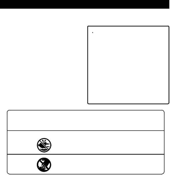
SAFETY AND INTERNATIONAL SYMBOLS
This operator's manual describes safety and international symbols and pictographs that may appear on this product. Read the operator's manual for complete safety, assembly, operating and maintenance, and repair information.
SYMBOL |
MEANING |
• Do not expose to rain or use in damp locations.
NO HANDS SYMBOL
• Failure to keep your hands away from the blade will result in serious personal injury.
SAVE THESE INSTRUCTIONS
Page 6
ELECTRICAL
DOUBLE INSULATION
Double insulation is a concept in safety in electric power tools, which eliminates the need for the usual three-wire grounded power cord. All exposed metal parts are isolated from the internal metal motor components with protecting insulation. Double insulated tools do not need to be grounded.
WARNING:
The double insulated system is intended to protect the user from shock resulting from a break in the tool’s internal insulation. Observe all normal safety precautions to avoid electrical shock.
Important: Servicing of a tool with double insulation requires extreme care and knowledge of the system and should be performed only by a qualified service technician. For service, we suggest you return the tool to your nearest authorized service center for repair. Always use original factory replacement parts when servicing.
ELECTRICAL CONNECTION
The saw has a precision-built electric motor. It should be connected to a power supply that is 120 volts, 60 Hz, AC only (normal household current). Do not operate this tool on direct current (DC). A substantial voltage drop will cause a loss of power and the motor will overheat. If your tool does not operate when plugged into an outlet, double-check the power supply.
EXTENSION CORDS
When using a power tool at a considerable distance from a power source, be sure to use an extension cord that has the capacity to handle the current the tool will draw. An undersized cord will cause a drop in line voltage, resulting in overheating and loss of power. Use the chart to determine the minimum wire size required in an extension cord. Only round jacketed cords listed by Underwriter’s Laboratories (UL) should be used.
When working outdoors with a tool, use an extension cord that is designed for outside use. This type of cord is designated with “WA” on the cord’s jacket.
Before using any extension cord, inspect it for loose or exposed wires and cut or worn insulation.
**Ampere rating (on tool faceplate)
|
0-2.0 |
2.1-3.4 |
3.5-5.0 5.1-7.0 |
7.1-12.0 |
12.1-16.0 |
|
Cord Length |
Wire Size (A.W.G.) |
|
|
|||
|
|
|
|
|
|
|
25' |
16 |
16 |
16 |
16 |
14 |
14 |
|
|
|
|
|
|
|
50' |
16 |
16 |
16 |
14 |
14 |
12 |
|
|
|
|
|
|
|
100' |
16 |
16 |
14 |
12 |
10 |
— |
|
|
|
|
|
|
|
**Used on 12 gauge - 20 amp circuit.
 CAUTION:
Keep the extension cord clear of the working area. Position the cord so that it will not get caught on lumber, tools or other obstructions while you are working with a power tool. Failure to do so can result in serious personal injury.
 WARNING:
Check extension cords before each use. If damaged replace immediately. Never use tool with a damaged cord since touching the damaged area could cause electrical shock resulting in serious injury.
Page 7

GLOSSARY OF TERMS
Anti-Kickback Pawls (Fingers)
Device which, when properly installed and maintained, is designed to stop the workpiece from being kicked back toward the front of the saw during a ripping operation.
Arbor
The shaft on which a blade or cutting tool is mounted.
Bevel Cut
A cutting operation made with an angled blade.
Compound Cut
A cut with both a miter angle and a bevel angle.
Crosscut
A cutting or shaping operation made across the grain of the workpiece.
Dado
A non-through cut which produces a square sided notch or trough in the workpiece.
Featherboard
A device used to help control the workpiece by guiding it securely against the table or fence during any rip cut operation.
Freehand
Performing a cut without using a fence, miter gauge, fixture, hold down clamp, or other proper device to keep the workpiece from twisting during the cut.
Gum
A sticky, sap based residue from wood products.
Heel
Misalignment of the blade.
Kerf
The amount of material removed by the blade in a through cut or the slot produced by the blade in a non-through or partial cut.
Kickback
An uncontrolled grabbing and throwing of the workpiece back toward the front of the saw. Associated with the workpiece closing the kerf and pinching the blade or otherwise placing tension on the blade.
Leading End
The end of the workpiece which, during a rip type operation, is pushed into the cutting tool first.
Miter Cut
A cutting operation made with the wood at any angle other than 90 degrees.
Molding
A cut which produces a special shape in the workpiece, used for joining or decoration.
Non-Through Cuts
Any cutting operation where the blade does not extend completely through the thickness of the workpiece.
Push Block
A device used to feed the workpiece through the saw, except during narrow ripping type operations where a push stick should be used. It also helps keep the operator's hands well away from the blade.
Push Stick
A device used to feed the workpiece through the saw to help keep the operator's hands well away from the blade.
Rabbet
A notch in the edge of a workpiece.
Resin
A sticky, sap base substance that has hardened.
Ripping Or Rip Cut
A cutting or shaping operation made along the length or with the grain of the workpiece.
Riving Knife/Spreader/Splitter
A metal piece, slightly thinner than the saw blade which helps keep the kerf open and prevent kickback.
Revolutions Per Minute (RPM)
The number of turns completed by a spinning object in one minute.
Saw Blade Path
The area over, under, behind, or in front of the blade. As it applies to the workpiece, that area which will be, or has been, cut by the blade.
Set
The distance that the tip of the saw blade tooth is bent (or set) outward from the face of the blade.
Throw-Back
Throwing of a workpiece in a manner similar to a kickback. Usually associated with a cause other than the kerf closing, such as a workpiece being dropped onto the blade or being placed inadvertently in contact with the blade.
Through Sawing
Any cutting operation where the blade extends completely through the thickness of the workpiece.
Trailing End
The workpiece end last cut by the blade in a ripping operation.
Workpiece
The item on which the cutting operation is being done. The surfaces of a workpiece are commonly referred to as faces, ends, and edges.
Page 8
UNPACKING
Your Model BTS15 Table Saw is shipped complete in one carton and includes a rip fence, a miter fence, and a blade guard.
Separate all parts from packing materials and check each one with the illustration and the list of Loose Parts to make sure all items are accounted for before discarding any packing material.
Important: Remove the foam block from between the saw's housing and the motor.
If any parts are missing, do not attempt to assemble the table saw, plug in the power cord, or turn the switch on until the missing parts are obtained and are installed correctly. Call 1-800-525-2579 for assistance if any parts are missing or damaged.
The saw is factory set for accurate cutting. After assembling it, check for accuracy. If shipping has influenced the settings, refer to specific procedures explained in the operation and maintenance sections of this manual.
WARNING:
If any parts are missing, do not operate this tool until the missing parts are replaced. Failure to do so could result in possible serious personal injury.
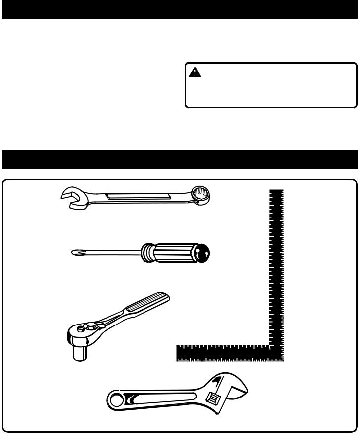
TOOLS NEEDED
1/2 in. WRENCH
#2 PHILLIPS SCREWDRIVER
FRAMING SQUARE
SOCKET WRENCH
WITH 7/16 in.
SOCKET
ADJUSTABLE WRENCH
Fig. 1
Page 9
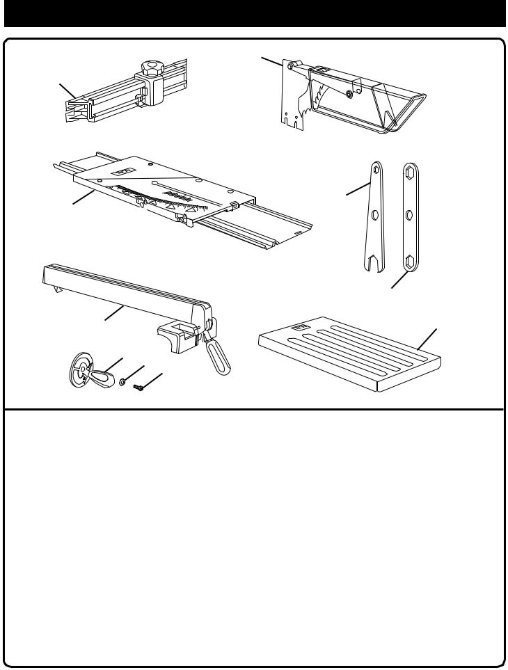
LOOSE PARTS LIST
2
1
 3 7
3 7 


|
|
4 |
|
6 |
5 |
|
8 |
|
|
9 |
10 |
|
|
Fig. 2 |
Key |
|
|
No. |
Description |
Qty. |
1 |
Miter Fence ...................................................................................................................................................... |
1 |
2 |
Blade Guard Assembly .................................................................................................................................... |
1 |
3 |
Small Wrench ................................................................................................................................................... |
1 |
4 |
Large Wrench................................................................................................................................................... |
1 |
5 |
Solid Table Extension ...................................................................................................................................... |
1 |
6 |
Rip Fence ......................................................................................................................................................... |
1 |
7 |
Sliding Miter Table ........................................................................................................................................... |
1 |
8 |
Blade Adjusting Handle .................................................................................................................................... |
1 |
9 |
Flat Washer ...................................................................................................................................................... |
1 |
10 |
Phillips Screw ................................................................................................................................................... |
1 |
11Operator's Manual (Not Shown)
12Warranty Registration Card (Not Shown)
Page 10
LOOSE PARTS LIST
The following items are included with your table saw leg stand.
 L
L
|
0 |
|
I |
M |
|
D |
|
|
D |
|
D |
|
J |
K |
D |
B |
Q |
|
HA 
D
G
N
N
C
G 
P
E
F
E
P
G
H
M
H
D I
H
C
D
G H
Q
N
Fig. 3
A. Storage Bracket ......................................................... |
2 |
B. Screw (1/4-20 x 1/2 in. Pan Hd.)................................ |
2 |
C. Lower Side Brace ....................................................... |
2 |
D. Hex Nut (5/16-18) .................................................... |
28 |
E. Washer (5/16 in.)........................................................ |
2 |
F. Leveling Foot ............................................................. |
1 |
G. Leg ............................................................................. |
4 |
H. Carriage Bolt (5/16-18 x 3/4 in.) .............................. |
24 |
I. Upper Brace ............................................................... |
2 |
J. Hex Nut (1/4-20) ......................................................... |
2 |
K. Washer (1/4 in.)........................................................... |
2 |
L. Bolt (5/16-18 x 2 in. Hex Hd.) ..................................... |
4 |
M. Upper Side Brace ........................................................ |
2 |
N. Foot ............................................................................. |
3 |
O. Washers ...................................................................... |
4 |
P. Hex Nut ....................................................................... |
2 |
Q. Lower Brace ................................................................ |
2 |
Page 11
FEATURES
Your saw is designed to perform as a versatile, accurate, precision cutting tool that is easy to operate.
It is equipped with the following features for convenience, ease of use, and high-quality performance:
•a combination saw blade
•a bevel indicator to set the exact angle of the blade, with locking lever
•an adjustable sliding miter table
•an adjustable miter fence
•an adjustable rip fence with scale indicator
•an adjustable riving knife (splitter) and blade guard with anti-kickback pawls
•front and rear guide rails with an easy-to-read scale on front rail
•blade adjusting handle to set depth of cut
•a sliding outfeed support
•switch with removable switch key to help prevent unauthorized use
•leg stand for ease of operation
These features provide ease of cutting with all types of wood.
 WARNING:
Before attempting to use your table saw, familiarize yourself with all operating features and safety requirements.
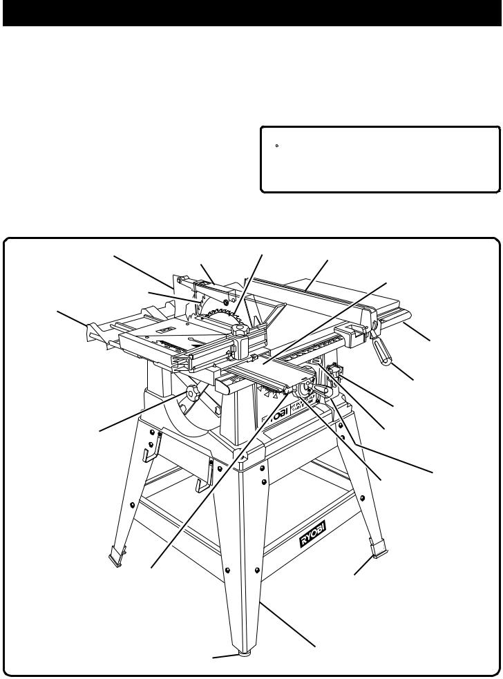
GETTING TO KNOW YOUR SAW
|
RIVING KNIFE |
BLADE GUARD |
SAW BLADE |
|
ASSEMBLY |
|
|
|
|
|
|
|
ANTI-KICKBACK |
|
|
OUTFEED |
PAWLS |
|
|
SUPPORT |
|
|
|
MITER FENCE 
BLADE AND
WRENCH
STORAGE
BEVEL
INDICATOR
LEVELING
FOOT
Page 12
RIP FENCE
SLIDING
MITER TABLE
FRONT
RAIL
LOCKING
HANDLE
SWITCH
BEVEL
LOCKING LEVER
BLADE
ADJUSTING
BEVEL HANDLE
HANDLE
FOOT
LEG STAND
Fig. 4
 Loading...