


4-Line Intercom Speakerphone
User’s Guide
Quick Guide on Pgs. 7-14
Please read this manual before operating product for the first time.
Model 25423/24

Important Information
Equipment Approval Information
Your telephone equipment is approved for connection to the Public Switched Telephone Network and is in compliance with parts 15 and 68, FCC Rules and Regulations and the Technical Requirements for Telephone Terminal Equipment published by ACTA.
1Notification to the Local Telephone Company
On the bottom of this equipment is a label indicating, among other information, the US number and Ringer Equivalence Number (REN) for the equipment. You must, upon request, provide this information to your telephone company.
The REN is useful in determining the number of devices you may connect to your telephone line and still have all of these devices ring when your telephone number is called. In most (but not all) areas, the sum of the RENs of all devices connected to one line should not exceed 5. To be certain of the number of devices you may
connect to your line as determined by the REN, you should contact your local telephone company.
A plug and jack used to connect this equipment to the premises wiring and telephone network must comply with the applicable FCC Part 68 rules and requirements adopted by the ACTA. A compliant telephone cord and modular plug is provided with this product. It is designed to be connected to a compatible modular jack that is also compliant. See installation instructions for details.
Notes
•This equipment may not be used on coin service provided by the telephone company.
•Party lines are subject to state tariffs, and therefore, you may not be able to use your own telephone equipment if you are on a party line. Check with your local telephone company.
•Notice must be given to the telephone company upon permanent disconnection of your telephone from your line.
•If your home has specially wired alarm equipment connected to the telephone line, ensure the installation of this product does not disable your alarm equipment. If you have questions about what will disable alarm equipment, consult your telephone company or a qualified installer.
US Number is located on the cabinet bottom
REN number is located on the cabinet bottom

Important Information
2Rights of the Telephone Company
Should your equipment cause trouble on your line which may harm the telephone network, the telephone company shall, where practicable, notify you that temporary discontinuance of service may be required. Where prior notice is not practicable and the circumstances warrant such action, the telephone company may temporarily discontinue service immediately. In case of such temporary discontinuance, the telephone company must: (1) promptly notify you of such temporary discontinuance;
(2) afford you the opportunity to correct the situation; and (3) inform you of your right to bring a complaint to the Commission pursuant to procedures set forth in Subpart E of Part 68, FCC Rules and Regulations.
The telephone company may make changes in its communications facilities, equipment, operations or procedures where such action is required in the operation of its business and not inconsistent with FCC Rules and Regulations. If these changes are expected to affect the use or performance of your telephone equipment, the telephone company must give you adequate notice, in writing, to allow you to maintain uninterrupted service.
Licensing
Licensed under US Patent 6,427,009.
Hearing Aid Compatibility
This telephone system meets FCC standards for Hearing Aid Compatibility.
WARNING: TO PREVENT FIRE OR ELECTRICAL SHOCK HAZARD, DO NOT EXPOSETHIS PRODUCT TO RAIN OR MOISTURE.
|
|
|
|
|
|
|
CAUTION: |
|
|
|
|
RISKOFELECTRICSHOCK |
|
|
|
|
DONOTOPEN |
|
|
THE LIGHTNING |
CAUTION: TO REDUCE THE |
THE EXCLAMATION |
||
FLASH AND ARROW |
RISK OF ELECTRIC SHOCK, DO |
POINT WITHIN THE |
||
HEAD WITHIN THE |
NOT REMOVE COVER (OR |
TRIANGLE IS A |
||
TRIANGLE IS A |
BACK). NO USER |
WARNING SIGN |
||
WARNING SIGN |
SERVICEABLE PARTS INSIDE. |
ALERTING YOU OF |
||
ALERTING YOU OF |
REFER SERVICING TO |
IMPORTANT |
||
“DANGEROUS |
QUALIFIED SERVICE |
INSTRUCTIONS |
||
VOLTAGE” INSIDE |
PERSONNEL. |
ACCOMPANYING |
||
THE PRODUCT. |
|
|
|
THE PRODUCT. |
|
|
|
|
|
SEE MARKING ON BOTTOM / BACK OF PRODUCT

Important Information
Interference Information
This device complies with Part 15 of the FCC Rules. Operation is subject to the following two conditions: (1) This device may not cause harmful interference; and (2) This device must accept any interference received, including interference that may cause undesired operation.
This equipment has been tested and found to comply with the limits for a Class B digital device, pursuant to Part 15 of the FCC Rules. These limits are designed to provide reasonable protection against harmful interference in a residential installation.
This equipment generates, uses, and can radiate radio frequency energy and, if not installed and used in accordance with the instructions, may cause harmful interference to radio communications. However, there is no guarantee that interference will not occur in a particular installation.
If this equipment does cause harmful interference to radio or television reception, which can be determined by turning the equipment off and on, the user is encouraged to try to correct the interference by one or more of the following measures:
•Reorient or relocate the receiving antenna (that is, the antenna for radio or television that is “receiving” the interference).
•Reorient or relocate and increase the separation between the telecommunications equipment and receiving antenna.
•Connect the telecommunications equipment into an outlet on a circuit different from that to which the receiving antenna is connected.
If these measures do not eliminate the interference, please consult your dealer or an experienced radio/television technician for additional suggestions. Also, the Federal Communications Commission has prepared a helpful booklet, “How To Identify and Resolve Radio/TV Interference Problems.” This booklet is available from the U.S. Government Printing Office, Washington, D.C. 20402. Please specify stock number 004-000-00345-4 when ordering copies.
Notice: The changes or modifications not expressly approved by the party responsible for compliance could void the user’s authority to operate the equipment.
FCC RF Radiation Exposure Statement
This equipment complies with FCC RF radiation exposure limits set forth for an uncontrolled environment. This equipment should be installed and operated with a minimum distance of 20 centimeters between the radiator and your body. This transmitter must not be co-located or operated in conjunction with any other antenna or transmitter.”
For body worn operation, this phone has been tested and meets the FCC RF exposure guidelines when used with the belt clip supplied with this product. Use of other accessories may not ensure compliance with FCC RF exposure guidelines.

Table of Contents
Equipm |
eAntpprov |
aInforml |
tiona...................... |
|
|
2 |
||||
Lic e nsing......................................................... |
|
|
|
|
|
|
|
3 |
||
Hea ringAid Compatibility................................ |
|
|
|
3 |
||||||
Int e rf e r e ncInforme |
tiona................................. |
|
|
|
|
4 |
||||
FCC |
|
RFa diRtiona Exposur |
State e m e .............nt |
4 |
||||||
Introduction.................................................... |
|
|
|
|
|
|
7 |
|||
Pa rts Che |
cklist............................................... |
|
|
|
|
|
|
8 |
||
Te l e p h onJaeck Re quir |
|
e m e...........................nts |
|
|
8 |
|||||
Ba s eLayout.................................................... |
|
|
|
|
|
|
9 |
|||
Importa nt Insta ll tiona |
Inform tiona................ |
|
10 |
|||||||
Importa nt Insta ll tiona |
Guid |
e lin................... |
e s |
|
10 |
|||||
Insta llingt he Ph one...................................... |
|
|
|
|
|
|
11 |
|||
Data |
Port..................................................... |
|
|
|
|
|
|
|
1 3 |
|
Syst |
e mVe rific tiona....................................... |
|
|
|
|
|
|
1 3 |
||
Ot he rSyst |
e mPh on |
....................................e s |
|
|
|
|
1 4 |
|||
Progr |
a mmingt he Te l e p h on...........................e |
|
|
1 4 |
||||||
Language............................................................. |
|
|
|
|
|
|
1 4 |
|||
Vo l ume................................................................ |
|
|
|
|
|
|
|
1 4 |
||
|
Ringe |
rVo l ume............................................... |
|
|
|
|
|
|
1 4 |
|
|
Speake r phone, Hand |
s,etand Head |
s et. |
|
||||||
|
Vo l ume........................................................... |
|
|
|
|
|
|
1 5 |
||
Ringe Trone........................................................ |
|
|
|
|
|
|
1 5 |
|||
Pr io r ityLine........................................................ |
|
|
|
|
|
|
1 5 |
|||
De l ayRing.......................................................... |
|
|
|
|
|
|
1 6 |
|||
Phone ID............................................................. |
|
|
|
|
|
|
1 6 |
|||
Phone Name........................................................ |
|
|
|
|
|
|
1 7 |
|||
Inte |
r comAuto An s we...................................... |
r |
|
|
|
1 7 |
||||
Fl a s hTime........................................................... |
|
|
|
|
|
|
1 8 |
|||
Ca llAl e r tTone.................................................. |
|
|
|
|
|
|
1 8 |
|||
No Unknown/Bl ocked....................................... |
|
|
|
|
1 8 |
|||||
Di s p l ayCont r a................................................s t |
|
|
|
|
|
1 9 |
||||
Loca |
Al r eaCode................................................ |
|
|
|
|
|
|
1 9 |
||
Regiona |
Arl eaCode ......................................... |
s |
|
|
|
|
1 9 |
|||
Manua |
yllSetting the Time and Date................ |
|
20 |
|||||||
Hou |
rFo r mat...................................................... |
|
|
|
|
|
|
21 |
||
Re s to r ingthe De f aut lSetting ......................... |
s |
|
21 |
|||||||
Ba sic Op e rtiona............................................. |
|
|
|
|
|
|
21 |
|||
Making Ca llswith the Hand s........................et |
|
21 |
||||||||
Making Ca llswith the |
Speake |
r phone............... |
2 2 |
|||||||
Making Ca llswith the Optiona |
Hlead |
s.........et |
2 2 |
|||||||
Pr e-dia |
l ing......................................................... |
|
|
|
|
|
|
2 2 |
||
An s we |
r ingCa lls............................................... |
|
|
|
2 3 |
|
Switching Between the Speake |
r phone, Hand |
s,et |
||||
and Head s..................................................et |
|
|
|
2 3 |
||
Mute................................................................... |
|
|
|
|
|
2 3 |
Do Not Di s tu rb................................................. |
|
|
|
2 4 |
||
Ho l d................................................................... |
|
|
|
|
2 4 |
|
Pl acing a Ca llon Ho l d............................... |
|
2 4 |
||||
Re l ea s inga Ca llfr omHo l d........................ |
|
2 4 |
||||
Fl a s..................................................................h |
|
|
|
|
2 4 |
|
Redia |
.................................................................l |
|
|
|
|
2 5 |
Re v iewingthe Redia |
Nl um |
b e.........................rs |
2 5 |
|||
Tr an |
sf e rr aingCa llto Anothe |
Srtation......... |
2 5 |
|||
Recei |
v inga Tr an |
sf e rrCaedllfr omAnothe |
r |
|||
Station........................................................... |
|
|
|
2 6 |
||
Me ss ageWaiting ............................................. |
|
|
|
2 6 |
||
Pr i v acy............................................................... |
|
|
|
|
2 6 |
|
Pr o v idingPr i v acy......................................... |
|
2 6 |
||||
Con |
f e r enceCa lls.............................................. |
|
|
|
2 6 |
|
Int e rcomCa lls............................................ |
|
|
|
2 7 |
||
One- Touch Inte r com......................................... |
|
2 7 |
||||
An s we |
r ingan Inte |
r comCa ll........................... |
|
2 8 |
||
Inte |
r comHo l d................................................... |
|
|
|
2 8 |
|
Inte |
r comCon f e r enceCa lls.............................. |
|
2 8 |
|||
Paging All Station .......................................... |
s |
|
2 9 |
|||
Ca ll e rID..................................................... |
|
|
|
|
2 9 |
|
Summa |
rScy r een............................................... |
|
|
|
2 9 |
|
Recei |
v ingand Sto r ingCID |
r ................d s |
2 9 |
|||
Re v iewingCID |
ecoR |
|
30 |
|||
Sav inga CID |
ecoR |
r tod the I nte r com/. |
|
|||
Memo |
rLyog o rto Phone Book Memo yr... |
30 |
||||
De l etinga CID |
ecoR |
|
30 |
|||
De l etingAll Ca ll Reco |
|
30 |
||||
Dia l ingBack................................................. |
|
|
|
30 |
||
If You Pr og r ammedYou rLoca |
Al r eaCode.... |
30 |
||||
If You Did Not Pr og |
r amYou rLoca Al r ea. |
|
||||
Code.............................................................. |
|
|
|
|
31 |
|
Ca llWaiting Ca ll e IDr |
|
31 |
||||
Memo rLyog and Phone Book ( Di r ecto )r y |
|
|||||
Memo |
r.........................................................y |
|
|
|
31 |
|
Sto r inga Num |
b eandr Name in . |
|
||||
Memo |
r.........................................................y |
|
|
|
31 |
|

Table of Contents |
|
|
|||
Re v iewingPhone Book |
( Di r ecto |
)r.y |
|||
Memo |
r..........................................................y |
|
3 2 |
||
Re v iewingthe Inte r com/ Memo rLyog |
|||||
(memo |
lrocationy)......................................... |
|
3 2 |
||
Editing a Name o rNum |
b e S rto r ed in P hone |
||||
Book ( Di r ecto )rMy emo |
3 3 |
||||
Editing a Name o rNum |
b e S rto r ed in the |
||||
Inte r com/ Memo rLyog . |
|
||||
( Memo rLyocation)........................................ |
|
3 3 |
|||
Sto r ingthe La s tNum |
b eDria l ed.................. |
3 3 |
|||
Sto r inga Pau s ine Memo r..........................y |
3 3 |
||||
Dia l inga |
Sto r edNum |
b ..............................e r |
3 3 |
||
Memo |
rDye l ete/ Cl ea ...................................r |
|
3 4 |
||
Cl ea rAll Memo r ......................................ie s |
3 4 |
||||
Chain Dia l ing................................................. |
|
3 5 |
|||
Displ ya Me ss a g..........................................e s |
|
3 5 |
|||
Op e rtiona By |
Batt e ry.................................... |
|
3 5 |
||
Op e rtiona wit |
h outPow e..............................r |
|
3 6 |
||
Cordl |
e ssPh on |
eOption.................................. |
|
3 6 |
|
Troubl |
e s h ootingGuid ...................................e |
|
3 6 |
||
Ge n e r aPlroduct Ca r ...................................e |
|
3 7 |
|||
Wa rr |
a ntyAssista nc ....................................e |
|
3 8 |
||
Acc e ssoryInform tiona.................................. |
|
3 9 |
|||
Limit |
e dWa rr a nty.......................................... |
|
40 |
||
Ind e............................................................x |
|
|
|
42 |
|

Important Information
Introduction
CAUTION: When using telephone equipment, there are basic safety instructions that should always be followed. Refer to the IMPORTANT SAFETY INSTRUCTIONS provided
with this product and save them for future reference.
Your Four-Line Speakerphone is a full-featured phone ideally suited for home-office use. It is designed to receive calls on up to four incoming telephone lines and to serve up to 16 station users. Your phone features 16 memory locations, 94 phone book memories, hold, conference call, intercom, call transfer, Caller ID display, and speakerphone capabilities. It
also features an Auto Attendant function, which will pick up and redirect incoming calls to
other extensions in the system per the caller’s input. It is possible to en to a cordless feature with the additional purchase of the H5401 accessory handset
and module.
This telephone is designed to be simple to use, however, you can reach its full potential more quickly by taking a few minutes to read this user’s guide.
IMPORTANT: In order to use all of the Caller ID features of this telephone, you must subscribe to two separate services available from your local telephone company: the standard Name/ Number Caller ID Service to know who is calling when the phone rings and Call Waiting Caller ID Service to know who is calling while you are on the phone.
NOTE: Features and options pertaining to Caller ID do not apply to Model 25423.
Connections & Setup
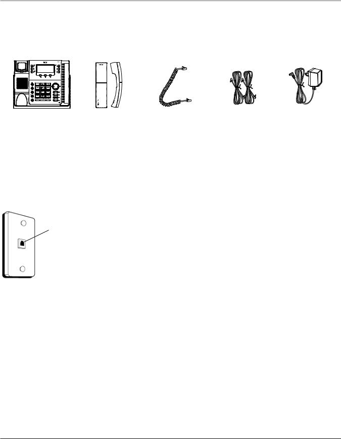
Parts Checklist
Make sure your package includes the following items:
Base |
Handset |
Handset cord |
Line cords |
AC power |
|
|
|
|
adaptor |
Telephone Jack Requirements
To use this phone, you will need an RJ11C (for a single line) or a RJ14C (for two lines) type modular phone jack, which might look like the one pictured here, installed in your home or office. If you don’t have either modular jack, call your local phone company to find out how to get one installed.
Wall plate
Modular telephone line jack
VERY IMPORTANT: In order to achieve full system operation (i.e. intercom, page, etc.), Line 1 must be connected and must be common to all phones connected to the system. Only other 25423, 25424, 25425, 25413, 25414, 25415, 25403 and 25404 models are compatible for full system operation. Connecting phones other than the 25423, 25424, 25425, 25413, 25414, 25415, 25403 and 25404 to Line 1 may inhibit the intercom and paging operations.
For proper operation of intercom, page function, etc., DO NOT connect a DSL modem to Line 1.
To transfer a call from one station to another, the two stations should be connected to the same line.

Connections & Setup
Base Layout
Privacy (button)
Menu (button)
Exit (button)
Redial/Format
(button)
Flash (button)
Transfer (button)
Conference (button)
Hold (button)
*
(button)
Headset (button)
|
New Message |
|
||
|
|
(indicator) |
|
|
|
only applicable for |
|
||
|
|
Model 25424 |
|
|
|
Dial |
|
Intercom |
|
|
(button) |
|
|
|
Delete |
|
(button) |
|
|
|
|
|
||
(button) |
Sel/Save |
Memory 1-16 |
|
|
|
(button) |
|
||
|
(buttons) |
|
||
|
|
|
|
|
|
|
|
Page |
|
|
|
|
(button) |
|
|
|
|
Store |
|
|
|
|
(button) |
|
|
|
|
Volume |
PQ |
|
|
|
(buttons) |
|
|
|
|
CID (button) |
|
|
|
|
only applicable for |
|
|
|
|
Model 25424 |
|
|
|
|
Line 4 |
|
|
|
|
(button) |
|
|
|
|
Line 3 |
|
|
|
|
(button) |
|
|
|
|
Line 2 |
|
|
|
|
(button) |
|
|
|
|
Line 1 |
|
Speaker |
#Pause |
|
(button) |
|
(button) |
(button) |
|
Microphone |
|
|
Mute |
|
(for speakerphone) |
|
|
|
DIRECTORY |
|
|
|
(button) |
|
|
|
|
|
|
(button) |
|

Connections & Setup
Important Installation Information
•Never install telephone wiring during a lightning storm.
•Never install telephone jacks in wet locations unless the jack is specifically designed for wet locations.
•Never touch non-insulated telephone wires or terminals, unless the telephone line is disconnected from the network.
•Use caution when installing or modifying telephone lines.
•Temporarily disconnect any equipment connected to the phone such as faxes, other phones, or modems.
Important Installation Guidelines
•Install telephone near both a telephone (modular) jack and an electrical power outlet.
•Avoid sources of noise, such as a window by a busy street, and electrical noise, such as motors, microwave ovens,
and fluorescent lighting.
•Avoid heat sources, such as heating air ducts, heating appliances, radiators, and direct sunlight.
•Avoid areas of excessive moisture or extremely low temperature.
•Avoid dusty locations.
•Avoid other cordless telephones or personal computers.
CAUTION: Always disconnect all phone cords from the base unit before battery installation or replacement.
10
Connections & Setup
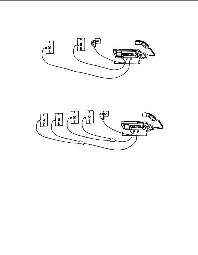
Installing the Phone
The phone may be connected to two 2-line (RJ14C) wall jacks or four single line (RJ11C) wall jacks to accomodate all four lines.
IMPORTANT: Install batteries and connect the AC power supply to the base unit as outlined in steps 1 through 3 below prior to connecting the telephone line cords to insure for proper base station ID assignment.
1.Choose an area near an electrical outlet and telephone wall jack. Your phone should be placed on a level surface, such as a table top or desk.
2.Install 4 AAA-size alkaline batteries (not included) for back up power in the event of a power failure.
•Insert a flat bladed screw driver into the battery door latch recess area and gently pry upward to release the battery door from the base cabinet bottom.
•Insert the batteries as shown on the diagram inside the battery compartment.
•Position the two (2) battery door tabs into the base cabinet bottom slots and push downward until the door latch “snaps” closed.
NOTE: If the low battery icon appears in the display, you need to replace the batteries. It is important that you replace them as soon as possible to maintain unit operation when
electrical power is off. As a precaution, you may want to write down any stored information you do not want erased.
IMPORTANT: If you are not going to use the telephone for more than 30 days, remove the batteries because they can leak and damage the unit.
3.Plug the power supply cord into the power jack on the back of the base and the other end into an electrical outlet.
CAUTION: To reduce risk of personal injury, fire, or damage use only the 5-2777 power adaptor listed in the user’s guide. This power adaptor is intended to be correctly orientated in a vertical or floor mount position.
11
Connections & Setup
4. Connect the telephone line cords:
If you have two dual line wall jacks installed in your home or office, plug one end of the straight telephone line cord tagged as “LINE 1+2” into the jack marked LINE 1 + 2 and one end of the other straight line cord into the other jack on the back of the base. Plug the other end of each line cord into the dual-line wall jacks.
If you have four single-line wall jacks installed in your home or office, you must use adaptors/couplers (not included) to combine the four single telephone lines into two dual lines. The adaptor/coupler may look similar to the one pictured here and can be purchased from your local telephone products retailer.
NOTE: To use four lines, you must have four telephone lines with unique telephone numbers. If you only have one telephone line, this phone will still operate, but only as a single line telephone.
Unit Initialization:
After you connect the power supply and Line 1 to the unit, the system automatically searches for and sets up a phone ID.
NOTE:
•If the phone cannot find an ID, determine if there are too many phones connected to the system. A maximum of 16 phones can be connected in the system.
•The Phone ID (01 to 16) is unique. When more than one phone using the same Phone ID is detected, only one phone with that ID will be valid. The phone IDs for the other phone(s) is automatically erased, and the phone(s) intercom indicators blink red and blue. You must use the Menu options to select a new Phone ID for each phone.
12

Connections & Setup
VERY IMPORTANT: In order to achieve full system operation (i.e. intercom, page, etc.), Line 1 must be connected and must be common to all phones connected to the system. Only
other 25413/14/15 models are compatible for full system operation. For proper operation of intercom, page function, etc., DO NOT connect a DSL modem to Line 1.
• To set your own Phone ID, or change your phone ID, follow the steps in the Phone ID section.
You may connect up to 16 RCA 25423, 25424 and/or 25425 phones to the system at one time. Features like intercom, page and call transfer may be used among the units, but Line 1 must be common for all 25423, 25424, or 25425 units for these features to work properly. You may choose to share or privatize lines 2, 3 and 4.
5.Connect the handset cord:
Connect one end of the coiled handset cord to the jack on the side of the base and the other end into the jack in the handset, and place the handset in the cradle.
6.Check for a dial tone:
Lift the handset and listen for a dial tone. If you hear a dial tone, the phone is properly installed.
Data Port
This phone has a data port jack to connect an auxiliary phone device, such as a fax machine, computer modem, answering machine, or even a cordless phone.
The data port switch on the back of the phone controls the data port jack so you can choose Line 1, Line 2, Line 3, or Line 4.
Use the data port to hook up your fax machine, for example, and then set the data port switch to Line 4 in order to receive faxes on the phone number for Line 4.
If you are talking to someone on Line 4 and want that person to fax something to you, change the data port switch to Line 2 or Line 3, and give the person on-line the phone number for Line 2 or Line 3. Your fax machine now can receive calls on Line 2, Line 3, or Line 4.
IMPORTANT: Be sure to switch the fax machine back to the normal line when you are done because outside callers who do not know that you have switched lines will not be able to reach your fax machine if they dial the Line 4 number.
System Verification
Use the following procedures to test system configuration and identify possible line connection errors. The phone must be connected to the power outlet, Line 1 must be connected to the Line 1 + 2 jack, and the phone must have a phone ID.
VERY IMPORTANT: In order to achieve full system operation (i.e. intercom, page, etc.), Line 1 must be connected and common to all phones on the system. Only other 25423, 25424, 25425, 25413, 25414, 25415, 25403 and 25404 models are fully compatible.
13

Programming the Telephone
Other System Phones
1.Press Line 1.
2.Look at all the other stations. If they all indicate line 1 is being used, the connection is correct.
OR |
|
1. Press the Intercom button. The display shows INTERCOM |
and ENTER CALLING PHONE ID |
2. Enter a phone ID by pressing an Intercom/Memo Log button (1-16). The display shows the phone ID you entered. If the phone ID you entered is connected to the system, you will hear a ring back tone (call through tone) at your phone. If the phone ID is not
connected to the system, you will hear an error tone. NO ANSWER and intercom is cancelled.
Programming the Telephone
When programming the phone, if at any time you wish to discontinue or stop programming, press the “Exit” button. Also , whenever you have made a program selection by pressing the Sel/Save button the display will shown “OK” for several seconds then will return to the MAIN MENU prompt display.
Language
Set the display language to show messages in either English, Spanish, or French.
1. Press the Menu button while in standby mode. The cursor in the display points to
SET LANGUAGE .
2.Press the Sel/Save button.
3.Use the Vol (+ or -) buttons to scroll up or down to ENGLISH, ESPANOL, or FRANCAIS The default is English.
4.Press the Sel/Save button to save.
Volume
The ringer, speaker, and handset/headset volume is set independently with the
Vol (+ or -) buttons. There are 8 possible volume settings per mode. The volume indicator scale is displayed during volume adjustment.
Ringer Volume
1.While the phone is on the hook, press the Vol (+ or -) button. The phone rings according to the current setting.
2.Tap the Vol (+ or -) buttons to adjust the volume one level at a time. The phone stores the setting after the last button press.
NOTE: To turn the ringer off, on, or change the ringing pattern, see Setting the Ringer Tone.
14
 Loading...