


AVIC-X1R

English
MANUEL D’INSTALLATION
AVIC-X1R
This product conforms to new cord colours.
Los colores de los cables de este producto se conforman con un nuevo código de colores.
Dieses Produkt entspricht den neuen kabelfarben.
Le code de couleur des câbles utilisé pour ce produit est
nouveau.
Questo prodotto è conforme ai nuovi codici colori.
De kleuren van de snoeren van dit toestel zijn gewijzigd.
Español
Deutsch
Français
Italiano
INSTALLATION MANUAL
Nederlands

IMPORTANT INFORMATION
ABOUT YOUR NEW NAVIGATION SYSTEM AND THIS MANUAL
• The navigation features of this unit (and rear view camera option if purchased) is
intended solely as an aid to you in the operation of your vehicle. It is not a substitute for your attentiveness, judgement and care when driving.
• Never use this Navigation System to route to hospitals, police stations, or similar
facilities in an emergency, Please call the appropriate emergency number.
• Do not operate this Navigation System (or the rear view camera option if purchased) if doing so in any way will divert your attention from the safe operation
of your vehicle. Traffic restrictions and advisories currently in force should
always take precedence over guidance given by this product. Always obey current
traffic restrictions, even if this product provides contrary advice.
• This manual explains how to install this Navigation System in your vehicle.
Operation of this Navigation System is explained in the separate “Operation
Manual” or “Hardware Manual” for Navigation System.
• Do not install the display unit or Hide-away unit where it may (i) obstruct the driver’s vision, (ii) impair the performance of any of the vehicle’s operating systems
of safety features, including airbags, hazard lamp buttons or (iii) impair the driver’s ability to safely operate the vehicle. In some cases, it may not be possible to
install this unit because of the vehicle type or the shape of the vehicle interior.
1

Contents
IMPORTANT INFORMATION .................... 1
ABOUT YOUR NEW NAVIGATION
SYSTEM AND THIS MANUAL .............. 1
IMPORTANT SAFEGUARDS .................... 3
PLEASE READ ALL OF THESE
INSTRUCTIONS REGARDING
YOUR NAVIGATION
SYSTEM AND RETAIN THEM
FOR FUTURE REFERENCE .................... 3
Connecting the System ............................ 4
-
Before installing the unit
-
To prevent damage
-
Parts supplied
Connecting the system ...................................... 7
Connecting the power cord (1) .......................... 9
Connecting the power cord (2) ........................ 11
When connecting to separately sold power
amp .......................................................... 13
When connecting with a Rear view
camera ...................................................... 15
When connecting the external video component
and the display .......................................... 16
-
When using a display connected to rear video
output
Installation ................................................ 17
To guard against electromagnetic
interference .............................................. 18
Before installing .............................................. 18
Installing the display unit and
Hide-away unit ........................................ 19
-
Installation notes
-
Parts supplied
-
Installing the Hide-away unit
-
DIN Front/Rear-mount
-
DIN Front-mount
-
DIN Rear-mount
-
Fixing the front panel
Installing the GPS aerial .................................. 26
-
Installation notes
-
Parts supplied
-
When installing the aerial inside the vehicle
(on the rear shelf)
-
When installing the aerial outside the vehicle
(on the body)
After Installing the Unit .......................... 29
English
Español
Deutsch
Français
Italiano
Nederlands
2
IMPORTANT SAFEGUARDS
PLEASE READ ALL OF THESE INSTRUCTIONS REGARDING YOUR
NAVIGATION SYSTEM AND RETAIN THEM FOR FUTURE REFERENCE
1. Read this manual fully and carefully before installing your Navigation System.
2. Keep this manual handy for future reference.
3. Pay close attention to all warnings in this manual and follow the instructions carefully.
4. This Navigation System may in certain circumstances display erroneous information regarding the position of your vehicle, the distance of objects shown on the
screen, and compass directions. In addition, the system has certain limitations,
including the inability to identify one-way streets, temporary traffic restrictions
and potentially unsafe driving areas. Please exercise your own judgement in the
light of actual driving conditions.
5. As with any accessory in your vehicle’s interior, the Navigation System should
not divert your attention from the safe operation of your vehicle. If you experience difficulty in operating the system or reading the display, please make adjustments while safely parked.
6. Please remember to wear your seat belt at all times while operating your vehicle.
If you are ever in an accident, your injuries can be considerably more severe if
your seat belt is not properly fastened.
7. Certain countries laws may restrict the placement and use of Navigation Systems
in your vehicle. Please comply with all applicable laws and regulations in the
installation and operation of your Navigation System.
Do not attempt to install or service your Navigation System by yourself.
Installation or servicing of the Navigation System by persons without training and
experience in electronic equipment and automotive accessories may be dangerous
and could expose you to the risk of electric shock or other hazards.
3

Connecting the System
• Pioneer does not recommend that you install your Navigation System yourself. We
recommend that only authorised Pioneer service personnel, who have special training and experience in mobile electronics, set up and install the unit. NEVER SERVICE THE UNIT YOURSELF. Installing or servicing the unit and its connecting
cables may expose you to the risk of electric shock or other hazards, and can cause
damage to the Navigation System that is not covered by warranty.
• If you decide to perform the installation yourself, and have special training and
experience in the mobile electronics installations, please carefully follow all of the
steps in the Installation Manual.
• Secure all wiring with cable clamps or electrical tape. Do not allow any bare wiring
to remain exposed.
• Do not directly connect the yellow lead of the unit to the vehicle battery. If the lead
is directly connected to the battery, engine vibration may eventually cause the insulation to fail at the point where the wire passes from the passenger compartment
into the engine compartment. If the yellow lead’s insulation tears as a result of contact with metal parts, short-circuiting can occur, resulting in considerable danger.
• It is extremely dangerous to allow the GPS aerial cable or microphone cable to
become wound around the steering column or gearstick. Be sure to install the unit,
its cables, and wiring away in such a way that they will not obstruct or hinder driving.
• Make sure that the cables and wires are routed and secured so they will not interfere with or become caught in any of the vehicle’s moving parts, especially the
steering wheel, gearstick, handbrake, sliding seat tracks, doors, or any of the vehicle’s controls.
• Do not route wires where they will be exposed to high temperatures. If the insulation heats up, wires may become damaged, resulting in a short circuit or malfunction and permanent damage to the product.
• Do not cut the GPS aerial cable to shorten it or use an extension to make it longer.
Altering the aerial cable could result in a short circuit or malfunction.
• Do not shorten any leads. If you do, the protection circuit (fuse holder, fuse resister
or filter, etc.) may fail to work properly.
• Never feed power to other electronic products by cutting the insulation of the
power supply lead of the Navigation System and tapping into the lead. The current
capacity of the lead will be exceeded, causing overheating.
• Do not earth more than one product together with the earth from another product.
For example, you must separately earth any amplifier unit away from the earth of
the Hide-away unit. Connecting earths together can cause a fire and/or damage the
products if their earths became detached.
English
Español
Deutsch
Français
Italiano
Nederlands
4
Connecting the System
Before installing the unit
• This unit is for vehicles with a 12-volt battery and negative earthing. Check the battery
voltage of your vehicle before installation.
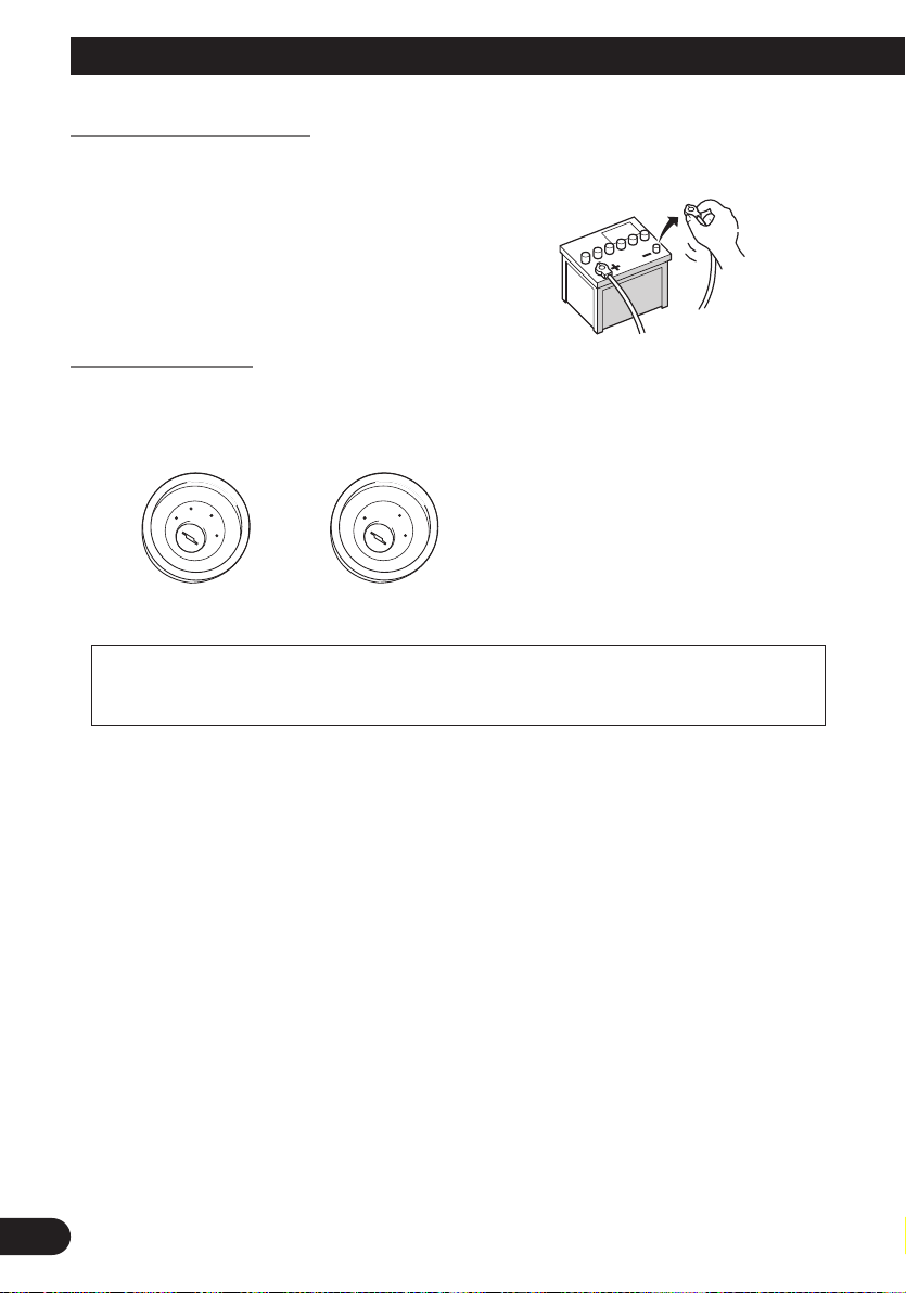
• To avoid shorts in the electrical system, be sure to disconnect the (–)
battery cable before beginning
installation.
To prevent damage
• When disconnecting a connector, pull the connector itself. Do not pull the lead, as you
may pull it out of the connector.
• This unit cannot be installed in a vehicle that does not have an ACC (accessory) position
on the ignition switch.
C
C
A
O
F
N
F
O
S
T
A
R
T
No ACC positionACC position
• When the auto aerial function is used by connecting the blue lead to the vehicle
with the auto aerial function, either turning off the ignition switch or detaching
the front panel will retract the auto aerial of the vehicle.
• To avoid short-circuiting, cover the disconnected lead with insulating tape. It is especially important to insulate all unused speaker leads, which if left uncovered may cause a
short circuit.
• Attach the connectors of the same colour to the corresponding coloured port, i.e., blue
connector to the blue port, black to black, etc.
• The black lead is earth. Please earth this lead separately from the earth of high-current
products such as power amps.
Do not earth more than one product together with the earth from another product. For
example, you must separately earth any amplifier unit away from the earth of the Hideaway unit. Connecting earths together can cause a fire and/or damage the products if
their earths became detached.
• Refer to the owner’s manual for details on connecting the power amp and other units,
then make connections accordingly.
• When replacing the fuse, be sure to only use a fuse of the rating prescribed on the fuse
holder.
• Since a unique BPTL circuit is employed, do not directly earth the ≠ side of the speaker
lead or connect the ≠ sides of the speaker leads together. Be sure to connect the ≠ side
of the speaker lead to the ≠ side of the speaker lead on the display unit.
• If the RCA pin jack on the unit will not be used, do not remove the caps attached to the
end of the connector.
5
O
F
N
F
O
S
T
A
R
T
• Never connect speakers with an output rating of less than 50 W channel or impedance
outside of the 4 ohms to 8 ohms specifications to your Navigation system. Connecting
speakers with output and/or impedance values other than those noted here may result in
the speakers catching fire, emitting smoke, or becoming damaged.
• When the ignition switch is turned on (ACC ON), a control signal is output through the
blue/white lead. Connect to an external power amp’s system remote control terminal
(max. 300 mA 12 V DC). The control signal is output through the blue/white lead, even
if the front panel is detached, or the audio source is switched off.
• When an external power amp is being used with this system, be sure not to connect the
blue lead to the amp’s power terminal. Likewise, do not connect the blue lead to the
power terminal of the auto aerial. Such connection could cause excessive current drain
and malfunction as well as damage to the auto aerial of the vehicle.
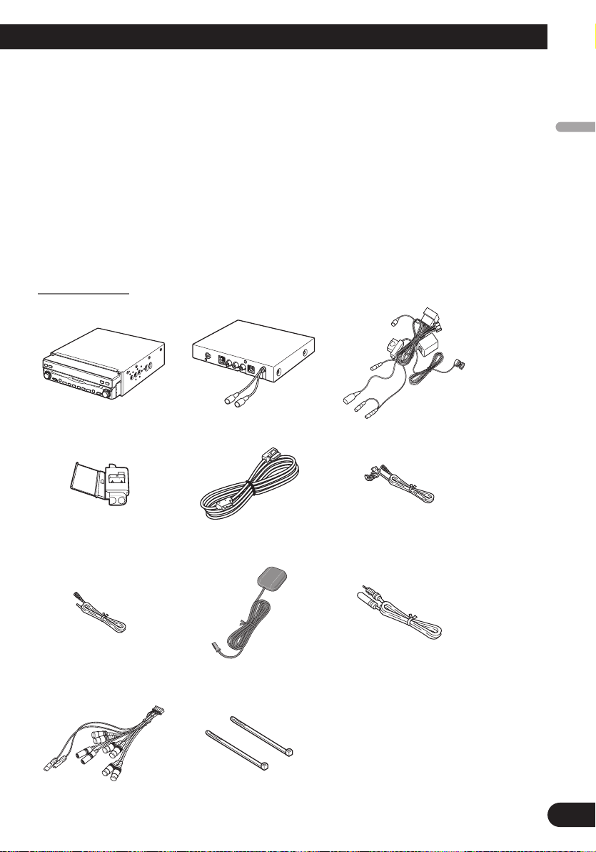
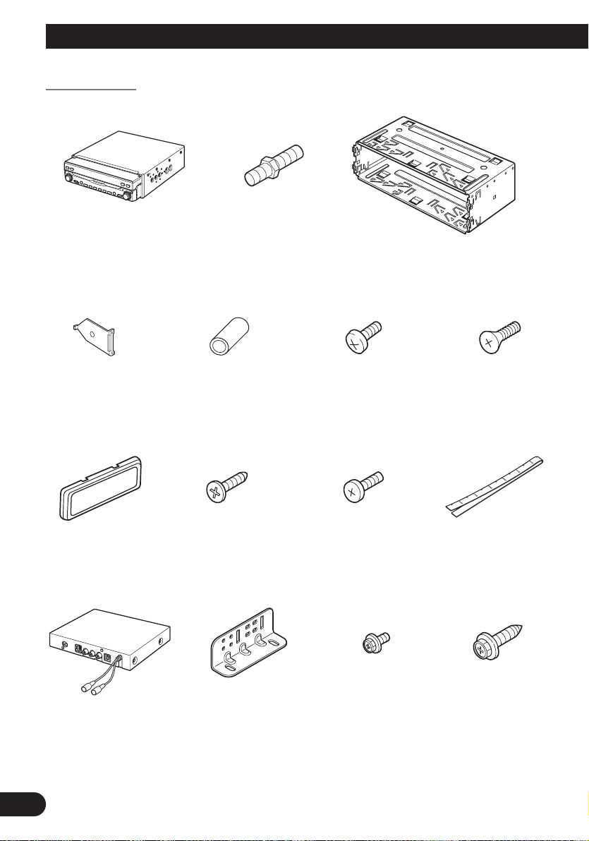
Parts supplied
Power cordHide-away unitDisplay unit
English
Español
Deutsch
Français
(for speed signal)
30-pin cableConnector
Extension lead
(for reverse signal)
Italiano
Extension aerial cableGPS aerialExtension lead
Lock tieSystem extension connector
Nederlands
6
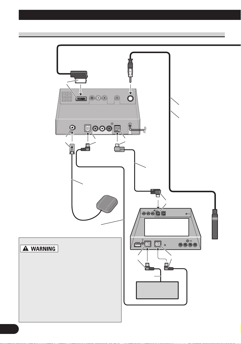
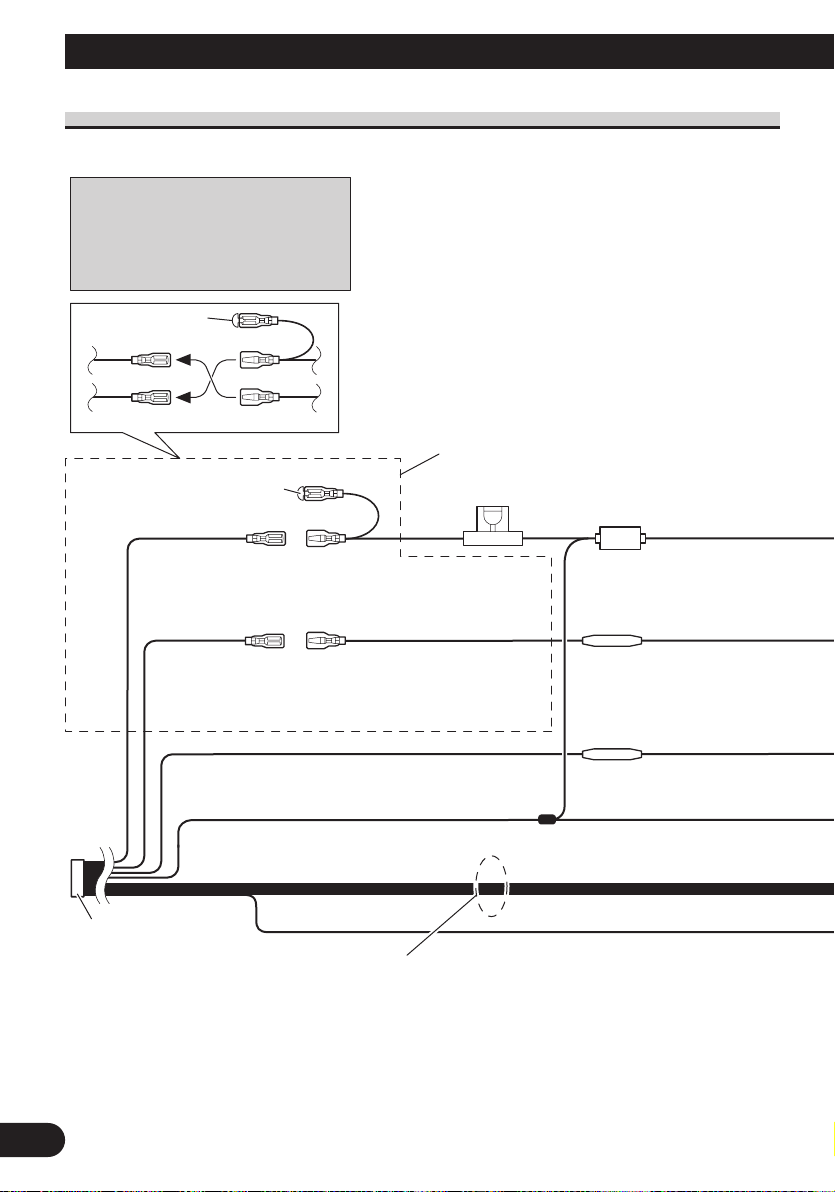
Connecting the System
Multi-CD player
Yellow
Hide-away unit
Blue
Blue
AV-BUS cable
(supplied with
TV tuner)
3 m
5 m
IP-BUS cable
IP-BUS cable
(supplied with TV tuner)
GPS aerial
When installing
the Hide-away unit
in the boot, etc.,
the extension cable
(e.g. CD-SC300E)
(sold separately)
is required.
(sold separately)
Black
BlackBlue
Hide-away TV tuner
(e.g. GEX-P6400TVP)
(sold separately)
Light grey
Extension
aerial cable
(supplied)
Connecting the system
• To avoid the risk of accident and the potential
violation of applicable laws, this unit should
never be used while the vehicle is being driven
except for Navigation purposes. And, also
Rear Displays should not be in a location
where it is a visible distraction to the driver.
• In some countries or states the viewing of
images on a display inside a vehicle even by
persons other than the driver may be illegal.
Where such regulations apply they must be
obeyed and this unit’s DVD or TV features
should not be used.
7

Yellow
DIGITAL OUT*
MIC INPUT
The microphone in the voice
recognition kit (e.g. CD-VC1)
(sold separately) is connected
when the voice recognition
function is used.
EXTENSION port
Not used.
3 m
30-pin cable (supplied)
Power cord
WIRED
REMOTE
Please see the Instruction
Manual for the Wired Remote
Control (sold separately).
Display unit
G.SP (Guidance speaker output)*
English
*: This terminal is intended to support future
equipment and should not be used if you
are using this product by itself.
Español
Deutsch
Français
Italiano
Nederlands
8
Connecting the System
Connect leads of the same
colour to each other.
Cap (*1)
When not using this terminal,
do not remove the cap.
ISO connector
Fuse holder
*1
*2
*4
*3
*5
Yellow (*2)
To terminal always supplied
with power regardless of
ignition switch position.
Red (*4)
To electric terminal controlled
by ignition switch (12 V DC)
ON/OFF.
Yellow (*3)
Back-up
(or accessory)
Red (*5)
Accessory
(or back-up)
Black (earth)
To vehicle (metal) body.
Orange/white
To lighting switch terminal.
Note:
In some vehicles, the ISO connector
may be divided into two. In this case,
be sure to connect to both connectors.
Fuse resistor
Fuse resistor
Note:
Depending on the kind of vehicle, the
function of *3 and *5 may be different.
In this case, be sure to connect *2 to *5
and *4 to *3.
Speaker leads
White: Front left +
White/black: Front left ≠
Grey: Front right +
Grey/black: Front right ≠
Green: Rear left + or Subwoofer +
Green/black: Rear left ≠ or Subwoofer ≠
Violet: Rear right + or Subwoofer +
Violet/black: Rear right ≠ or Subwoofer ≠
Connecting the power cord (1)
9

GUIDE ON
SYSTEM REMOTE
CONTROL
Blue (*7)
ToAuto-aerial relay control terminal
(max. 300 mA 12 V DC).
Blue (*6)
The pin position of the ISO connector will differ
depending on the type of vehicle. Connect *6 and
*7 when Pin 5 is an aerial control type. In
other types of vehicle, never connect *6 and *7.
Y
Light green
ellow/black
If you use a cellular telephone, connect it via the
Audio Mute lead on the cellular telephone. If not,
keep the Audio Mute lead free of any
connections.
When the auto aerial function is used by connecting
the blue lead to the vehicle with the auto aerial function,
either turning off the ignition switch or detaching the
front panel will retract the auto aerial of the vehicle.
Note:
Note:
Audio source will be set to mute or attenuate,
while the voice guidance of the navigation
will not be muted or attenuated. For details,
see the “Operation Manual”.
Display unit
See Page 12.
☞
☞
Note:
Cords for this product and those for other products
may be different colours even if they have the same
function. When connecting this product to another
product, refer to the supplied manuals of both products and connect cords that have the same function.
See Page 11.
English
Español
Deutsch
Français
Italiano
Nederlands
10
Pink (CAR SPEED SIGNAL INPUT)
The mobile navigation system is connected here to detect the distance
the vehicle travels. Always connect the vehicle’s speed detection
circuit or the ND-PG1 speed pulse generator, sold separately. Failure
to make this connection will increase errors in the location display.
IMPROPER CONNECTION MAY RESULT IN SERIOUS
DAMAGE OR INJURY INCLUDING ELECTRICAL SHOCK,
AND INTERFERENCE WITH THE OPERATION OF THE
VEHICLE’S ANTILOCK BRAKING SYSTEM, AUTOMATIC
GEARBOX AND SPEEDOMETER INDICATION.
Light green
Used to detect the ON/OFF status of the handbrake. This lead must be
connected to the power supply side of the handbrake switch. If this
connection is made incorrectly or omitted, certain functions of
your navigation system will be unusable.
LIGHT GREEN LEAD AT POWER
CONNECTOR IS DESIGNED TO DETECT
PARKED STATUS AND MUST BE
CONNECTED TO THE POWER SUPPLY SIDE
OF THE HANDBRAKE SWITCH. IMPROPER
CONNECTION OR USE OF THIS LEAD MAY
VIOLATE APPLICABLE LAW AND MAY
RESULT IN SERIOUS INJURY OR DAMAGE.
Connecting the System
Connecting the power cord (2)
Speed detection circuit lead
Vehicle injection
computer
Note: The position of the speed
detection circuit depends on the
vehicle model. For details, consult
your authorised Pioneer dealer or
an installation professional.
If connection to the speed detection circuit is too difficult, connect
the separately sold ND-PG1 speed
pulse generator to the pink lead.
Note: The position of the handbrake switch depends on the vehicle model. For details, consult the
vehicle owner’s manual or dealer.
Connection method
Pass the extension cord
Connector
and the lead for the speed
detection circuit through
this hole.
Clamp firmly with
needle-nosed
pliers.
Close the cover.
Hide-away unit
Extension lead
(for speed signal)
Connection method
Clamp the handbrake switch
power supply side lead.
Clamp firmly with
needle-nosed pliers.
11
Power supply side
Earth side
Handbrake switch
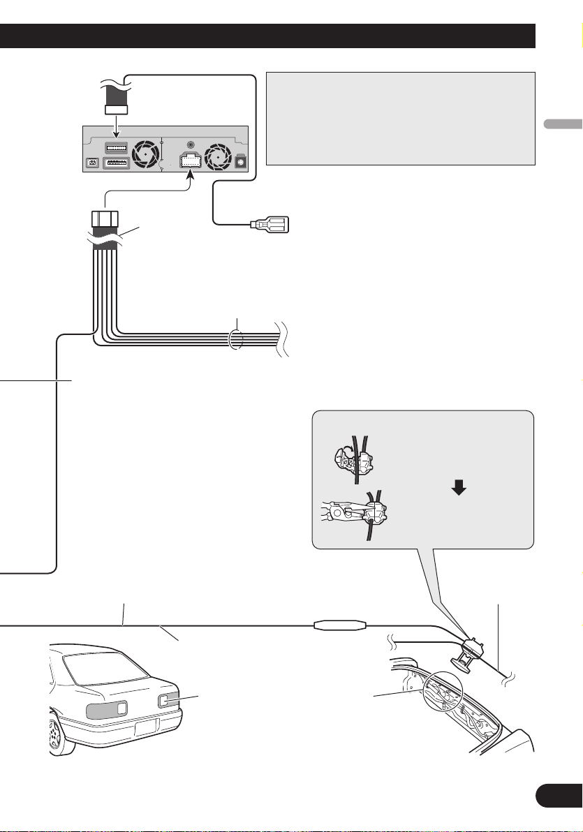
Note:
Display unit
Power cord
Black, Orange/white, Red, Yellow
Cords for this product and those for other products may
be different colours even if they have the same function. When connecting this product to another product,
refer to the supplied Installation manuals of both products and connect cords that have the same function.
Violet/white (REVERSEGEAR SIGNAL INPUT)
This is connected so that the navigation system can
detect whether the vehicle is moving forwards or
backwards. Connect the violet/white lead to the
lead whose voltage changes when the reverse gear
is engaged. Unless connected, the sensor may not
detect your vehicle travelling forward/backward
properly, and thus the position of your vehicle
detected by the sensor may be misaligned from the
actual position.
Yellow/black (GUIDE ON)
When combining this navigation unit with the other
Pioneer audio unit for the vehicle, if the vehicle
stereo has yellow/black leads, connect them to those
leads. In this way, when the guidance audio is output
and when you operate the system by voice, the vehicle stereo is automatically muted to reduce the vehicle stereo volume.
See Page 9.
☞
Connection method
Clamp the reversing lamp
lead.
English
Español
Deutsch
Français
Note: When you use the ND-PG1 speed pulse
generator (sold separately), please make sure
to connect it.
When you use a rear view camera, please make
sure to connect it. Otherwise you cannot switch to
rear view camera picture.
Do not use other than the supplied extension lead.
See Page 15.
☞
Extension lead
(for reverse signal)
Check the position of your vehicle’s
reversing lamp (the one that lights up
when the gearstick is in reverse [R]) and
find the reversing lamp lead in the boot.
Clamp firmly with
needle-nosed pliers.
Italiano
Reversing lamp lead
Fuse resistor
Nederlands
12
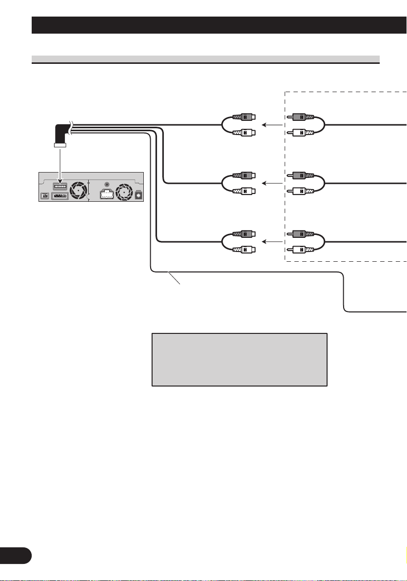
Connecting the System
Display unit
Front output
(FRONT OUTPUT)
Subwoofer output
or non-fading output
(SUBWOOFER OUTPUT or
NON-FADING OUTPUT)
Rear output
(REAR OUTPUT)
15 cm
20 cm
15 cm
Blue/white
To system control terminal of the power amp
(max. 300 mA 12 V DC).
Do not connect this lead to Auto-aerial control
terminal.
Note:
When a subwoofer is connected to this unit instead
of a rear speaker, change the rear output setting in
the Initial Setting. (Refer to the Operation Manual.)
The subwoofer output of this unit is monaural.
When connecting to separately sold power amp
13
English
Power amp
(sold separately)
Power amp
(sold separately)
Power amp
(sold separately)
+
≠
+
≠
+
≠
+
≠
+
≠
+
≠
System remote control
RCA cables
(sold separately)
Front speaker
Rear speaker
Subwoofer
Front speaker
Rear speaker
Subwoofer
Left Right
Perform these connections when using
the optional amplifier.
Español
Deutsch
Français
Italiano
Nederlands
14
Connecting the System
When connecting a Rear view camera
When using this product with a rear view camera, automatic switching to video from a rear
view camera is possible when the gear shift is moved to REVERSE (R) position.
Rear view mode also allows you to check what is behind you while driving.
USE INPUT ONLY FOR REVERSE OR MIRROR IMAGE REAR VIEW CAMERA. OTHER USE
MAY RESULT IN INJURY OR DAMAGE.
• The screen image may appear reversed.
• The rear view camera function is to use this product as an aid to keep an eye on trailers, or backing
into a tight parking spot. Do not use this function for entertainment purposes.
• The object in rear view may appear closer or more distant than in reality.
• Please note that the edges of the rear view camera images may differ slightly according to whether
full screen images are displayed when backing, and whether the images are used for checking the
rear when the vehicle is moving forward.
See Page 11.
☞
8 m
Hide-away unit
Note:
It is necessary to set to CAMERA in
SETUP when connecting the rear
view camera.
15
Brown
Extension lead
(for reverse signal)
Fuse resistor
Note:
Do not use other than the
supplied extension lead.
Connection method
Clamp the lead.1. 2. Clamp firmly with
RCA cable
(sold separately)
Rear view camera
To video output
Note:
Connect to the rear view camera. Do not connect to
any other equipment.
needle-nosed
pliers.
When connecting the external video component and the display
RCA cables
(sold separately)
To audio inputs
Display with
RCA input jacks
To video input
English
Note:
The map screen navigation images
output to the rear display differ from
standard NTSC format images.
Therefore, their quality will be inferior to the images that appear on the
Hide-away unit
RCA cables
(sold separately)
To audio outputs
To video output
front display.
External video
component
(sold separately)
• It is necessary to set to AV INPUT or REAR DISP in SET UP when connecting the
external video component.
When using a display connected to rear video output
This product’s rear video output is for connection of a display to enable passengers in the
rear seats to watch the DVD, etc.
Español
Deutsch
Français
Italiano
• NEVER install the rear display in a location that enables the Driver to watch the DVD while
Driving.
• NEVER connect rear audio output (REAR OUT) to separately sold power amp.
Nederlands
16

Installation
• Pioneer does not recommend that you install or service your Navigation
System yourself. Installing or servicing the product may expose you to risk of
electric shock or other hazards. Refer all installation and servicing of your
navigation unit to authorised Pioneer service personnel.
• Never install the unit in places, or in a manner that where:
* It could injure the driver or passengers if the vehicle stops suddenly.
* It may interfere with the driver’s operation of the vehicle, such as on the
floor in front of the driver’s seat, or close to the steering wheel or gearstick.
• Make sure there is nothing behind the dashboard or panelling when drilling
holes in them. Be careful not to damage fuel lines, brake lines, electronic
components, communication wires or power cables.
• When using screws, do not allow them to come into contact with any electrical lead. Vibration may damage wires or insulation, leading to a short circuit
or other damage to the vehicle.
• To ensure proper installation, use the supplied parts in the manner specified.
If any parts other than the supplied ones are used, they may damage internal
parts of the unit or they may work loose and the unit may become detached.
• It is extremely dangerous to allow the GPS aerial lead or microphone lead to
become wound around the steering column or gearstick. Be sure to install
the unit in such a way that it will not obstruct driving.
• Make sure that leads cannot get caught in a door or the sliding mechanism of
a seat, resulting in a short circuit.
• Please confirm the proper function of your vehicle’s other equipment following installation of the Navigation System.
• Certain government laws may prohibit or restrict the placement and use of
this system in your vehicle. Please comply with all applicable laws and regulations regarding the use, installation and operation of your Navigation
System.
• Do not install the display unit or Hide-away unit where it may (i) obstruct
the driver’s vision, (ii) impair the performance of any of the vehicle’s operating systems or safety features, including airbags, hazard lamp buttons or (iii)
impair the driver’s ability to safely operate the vehicle.
17

• Install the display unit between the driver’s seat and front passenger seat so
that it will not be hit by the driver or passenger if the vehicle stops quickly.
• Never install the display unit in front of or next to the place in the dash,
door, or pillar from which one of your vehicle’s airbags would deploy. Please
refer to your vehicle’s Owner’s Manual for reference to the deployment area
of the frontal airbags.
• Do not install the display unit and Hide-away unit in a place where it will
impair the performance of any of the vehicle’s operating systems, including
airbags and headrests.
To guard against electromagnetic interference
• In order to prevent interference, set the following items as far as possible from the dis-
play unit and Hide-away unit of this Navigation System, other cables or leads:
- TV aerial and aerial lead
- FM, MW/LW aerial and its lead
- GPS aerial and its lead
In addition you should lay or route each aerial lead as far as possible from other aerial
leads.
Do not bind them together, lay or route them together, or cross them.
Such electromagnetic noise will increase the potential for errors in the location display.
English
Español
Deutsch
Before installing
• Consult with your nearest dealer if installation requires the drilling of holes or other mod-
ifications of the vehicle.
• Before making a final installation of the unit, temporarily connect the wiring to confirm
that the connections are correct and the system works properly.
Français
Italiano
Nederlands
18
Installation
5°
Installing the display unit and Hide-away unit
Installation notes
• Do not install the display unit or Hide-away unit in places where it may become subject
to high temperatures or humidity, such as:
* Places close to a heater, vent or air conditioner.
* Places exposed to direct sunlight, such as on top of the dashboard or the rear shelf.
* Places that may be splashed by rain, for example close to the door.
• When installing the unit choose a position that is strong enough to bear the weight of the
unit. Choose positions where the display unit or Hide-away unit can be firmly installed,
and install it securely.
Unless the display unit or Hide-away unit are securely attached, the current location of
the vehicle cannot be displayed correctly.
• Do not install the Hide-away unit on the board covering the spare tyre or other places
which are subject to vibration.
• When the Hide-away unit is installed under a front seat, ensure that it does not obstruct
the sliding action of the seat.
• When installing the Hide-away unit, choose a position that ensures there will be no contact with luggage. The impact of a heavy weight or sudden shock on the Hide-away unit
will adversely affect the accurate display of the current location of the vehicle.
• Avoid installing the Hide-away unit in places where it will interfere with loading and
unloading of the spare tyre, jack, tools, etc.
• Check that a disc can be ejected with the display unit installed.
• Install the Hide-away unit horizontally on a surface within +30 degrees to -30 degrees
tolerance (within five degrees to the left or right of your vehicle’s direction of travel).
Mis-installing the unit with the surface tilted more than these tolerances would increase
the potential for errors in the location display, and might otherwise cause reduced display performance.
30°
30°
• If installation angle exceeds 30º from horizontal, the display unit might not give its optimum performance.
30°
19

• The cords must not cover up the area shown in the figure below. This is necessary to
allow the amplifiers and navigation mechanism to heat dissipate freely.
Display unit
Do not cover this area.
• The semiconductor laser will be damaged if it overheats, so don’t install the unit anywhere hot — for instance, near a heater outlet.
• When installing the Hide-away unit in the boot, use the extension cable (e.g. CDSC300E) (sold separately).
• Do not install the display unit in a position where the opening of the LCD panel is
obstructed by any obstacles, such as the gearstick. This may cause interference with the
gearstick, or a malfunction of the mechanism of the display unit.
Hide-away unit
Do not cover this area.
English
Español
Deutsch
Français
Italiano
Nederlands
20
Installation
Parts supplied
Display unit
Side bracket
(2 pcs.)
Frame Screw
Rubber bush
(4 × 3 mm)
(4 pcs.)
Screw
Binding screw
(5 × 6 mm)
(4 pcs.)
Fixing screw
(2 pcs.)
Holder
Flush surface screw
(5 × 6 mm)
(4 pcs.)
Conceal tape
21
Hide-away unit
Side bracket
(2 pcs.)
Washer faced screw
(4 × 8 mm)
(4 pcs.)
Self-tapping screw
(6 × 16 mm)
(4 pcs.)
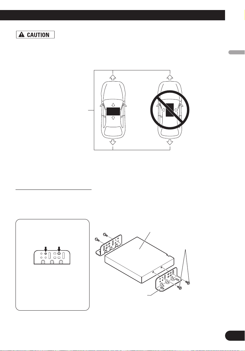
• Install with the left and right sides of the Hide-away unit perpendicular or parallel to your vehicle’s direction of travel. Do not install diagonally to your vehicle’s direction of travel or the current location will be displayed incorrectly.
English
Forward/Backward
direction of vehicle
• Be sure to install the Hide-away unit on the floor with the silk printing side is
facing up. The navigation system will operate properly only in this position.
Installing the Hide-away unit
1. Attach the side brackets to the Hide-away unit.
When the Hide-away unit is installed on the floor or the installation board under the passenger seat, etc., the side brackets should be attached to the unit.
Use the following holes in
the side brackets.
Hide-away unit
Washer faced screw
(4 × 8 mm)
Español
Deutsch
Français
Italiano
If the positions of the side
plates are shifted in parallel you can also use other
holes that match up with
the holes in the Hideaway unit.
Nederlands
Side bracket
22
Installation
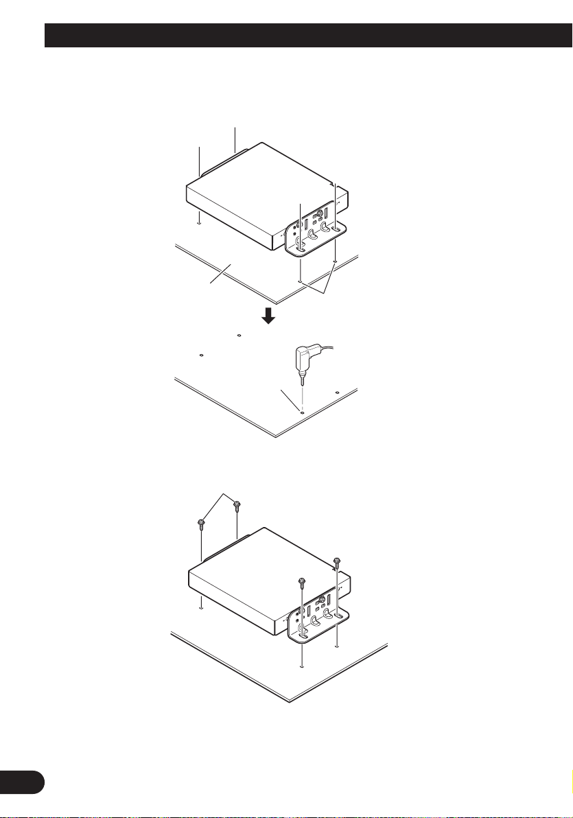
When the Hide-away unit is installed under the passenger seat, etc., use the installation
board.
2. Decide on the installation position, and drill the holes.
Installation board
Drill holes of between 4
and 4.5 mm in diameter.
Mark up the positions
for drilling the holes.
3. Secure it firmly using the self-tapping screws.
Self-tapping screw
(6 × 16 mm)
23

DIN Front/Rear-mount
This unit can be properly installed
either from “Front” (conventional DIN
Front-mount) or “Rear” (DIN Rearmount installation, using threaded
screw holes at the sides of unit chassis). For details, refer to the following
illustrated installation methods.
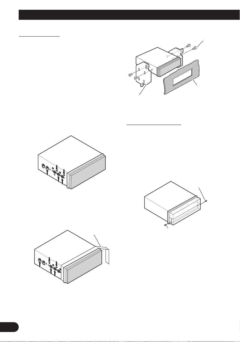
Before installing the unit
• Remove the frame and the
holder.
To remove the frame, extend top and
bottom of the frame outwards in order
to unlock it.
Loosen the screws (2 × 3 mm) to
remove the holder. (When reattaching
the frame, point the side with a groove
downwards and attach it.)
• It becomes easy to remove the frame
if the front panel is released.
Conceal tape
Side bracket
Flush surface screw (5 × 6 mm)
2. Install the unit into the dashboard.
After inserting the holder into the
dashboard, select the appropriate tabs
according to the thickness of the dashboard material and bend them.
(Install as firmly as possible using the
top and bottom tabs. To secure, bend
the tabs 90 degrees.)
Dashboard
English
Español
Deutsch
Holder
Screw (2 × 3 mm)
Frame
DIN Front-mount
Installation with the rubber bush
1. Decide the position of the side
brackets.
When installing in a shallow space,
change the position of side brackets. In
this case, stick conceal tape on parts
that protrude from the dashboard.
182
53
Holder
Side bracket
Screw (2 × 3 mm)
Rubber bush
Scre
w
• After installing the unit into the
dashboard, reattach the frame.
• If you prefer an off-set installation
in which the front panel is pushed
further back, when there is a space
available at the back of the unit, use
AD-GA10 (sold separately).
Français
Italiano
Nederlands
24
Installation
*
1
*
1
DIN Rear-mount
Installation using the screw holes on the
side of the unit
• Fastening the unit to the factory
radio-mounting bracket.
Select a position where the screw holes
of the bracket and the screw holes of
this product become aligned (are fitted), and tighten the screws at 2 places
on each side. Use any of screws (4 × 3
mm), binding screws (5 × 6 mm) or
flush surface screws (5 × 6 mm),
depending on the shape of the screw
holes in the bracket.
*1 Use screws (4 × 3 mm) only.
Binding screw
(5 × 6mm)
Dashboard or
Console
Factory radio mounting
bracket
Fixing the front panel
If you do not operate the removing and
attaching the front panel function, use
the supplied fixing screws to fix the
front panel to this unit.
• Fix the front panel to the unit
using fixing screws after removing the front panel.
Fixing screw
• When installing in a shallow space,
use the following screw holes. In
this case, stick conceal tape on parts
that protrude from the dashboard.
1
*
1
*
25
Conceal tape
Fixing screw
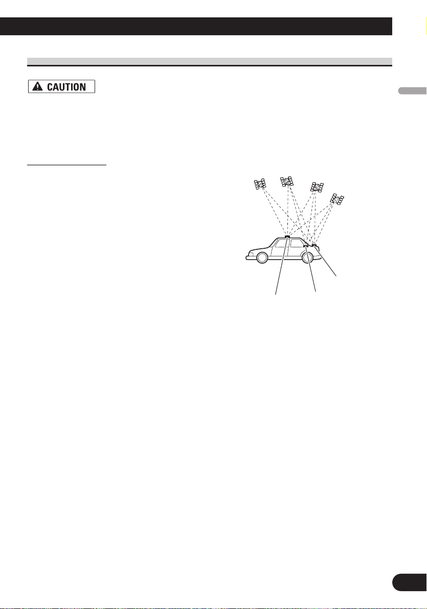
Installing the GPS aerial
• Do not cut the GPS aerial lead to shorten it or use an extension to make it
longer. Altering the aerial cable could result in a short circuit or malfunction
and permanent damage to the product.
Installation notes
• The aerial should be installed on a
level surface where radio waves will
be blocked as little as possible. Radio
waves cannot be received by the aerial
if reception from the satellite is
blocked.
Installation on the vehicle roof or boot
lid is recommended to optimise reception.
Boot lid
Roof
• When installing the GPS aerial inside the vehicle, be sure to use the metal sheet
provided with your system. If this is not used, the reception sensitivity will be poor.
• Do not cut the accessory metal sheet. This would reduce the sensitivity of the GPS
aerial.
• Take care not to pull the aerial lead when removing the GPS aerial. The magnet attached
to the aerial is very powerful, and the lead may become detached.
• The GPS aerial is installed with a magnet. When installing the GPS aerial, be careful
not to scratch the vehicle body.
• When installing the GPS aerial on the outside of the vehicle, always put it in the vehicle
when going through an automatic vehicle wash. If it is left on the outside it may be
knocked off and scratch the vehicle body.
• Do not paint the GPS aerial, as this may affect its performance.
Rear shelf
English
Español
Deutsch
Français
Italiano
Nederlands
26
Installation
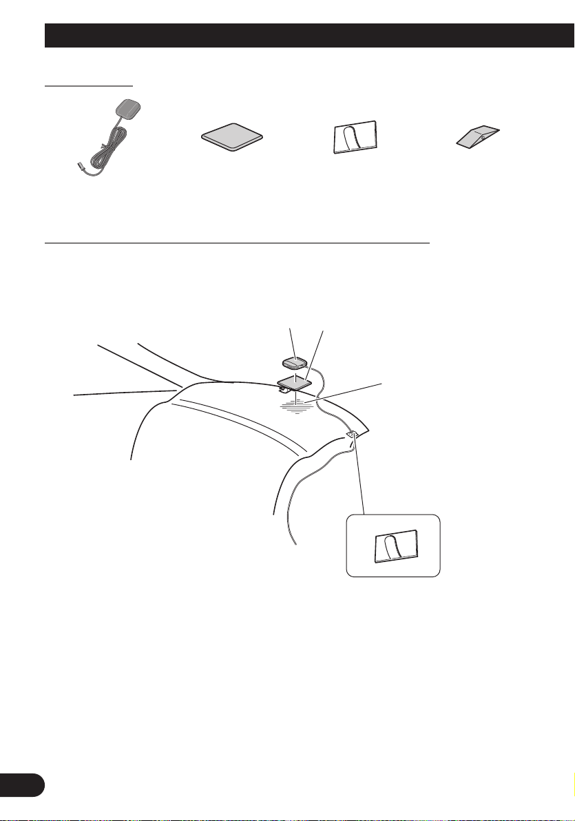
Parts supplied
Waterproof padClamp (5 pcs.)Metal sheetGPS aerial
When installing the aerial inside the vehicle (on the rear shelf)
Affix the metal sheet on as level a surface as possible where the GPS aerial faces the window. Place the GPS aerial on the metal sheet. (The GPS aerial is fastened with its magnet.)
GPS aerial
Note:
• When attaching the metal sheet, do not cut it into small pieces.
• Some models use window glass that does not allow signals from GPS satellites to pass through. On
such models, install the GPS aerial on the outside of the vehicle.
Metal Sheet
Peel off the protective sheet
on the rear.
Make sure the surface is
free of moisture, dust,
grime, oil, etc., before
affixing the metal sheet.
Note: The metal sheet
contains a strong adhesive
which may leave a mark on
the surface if it is removed.
Clamps
Use clamps to secure the
lead where necessary inside
the vehicle.
27
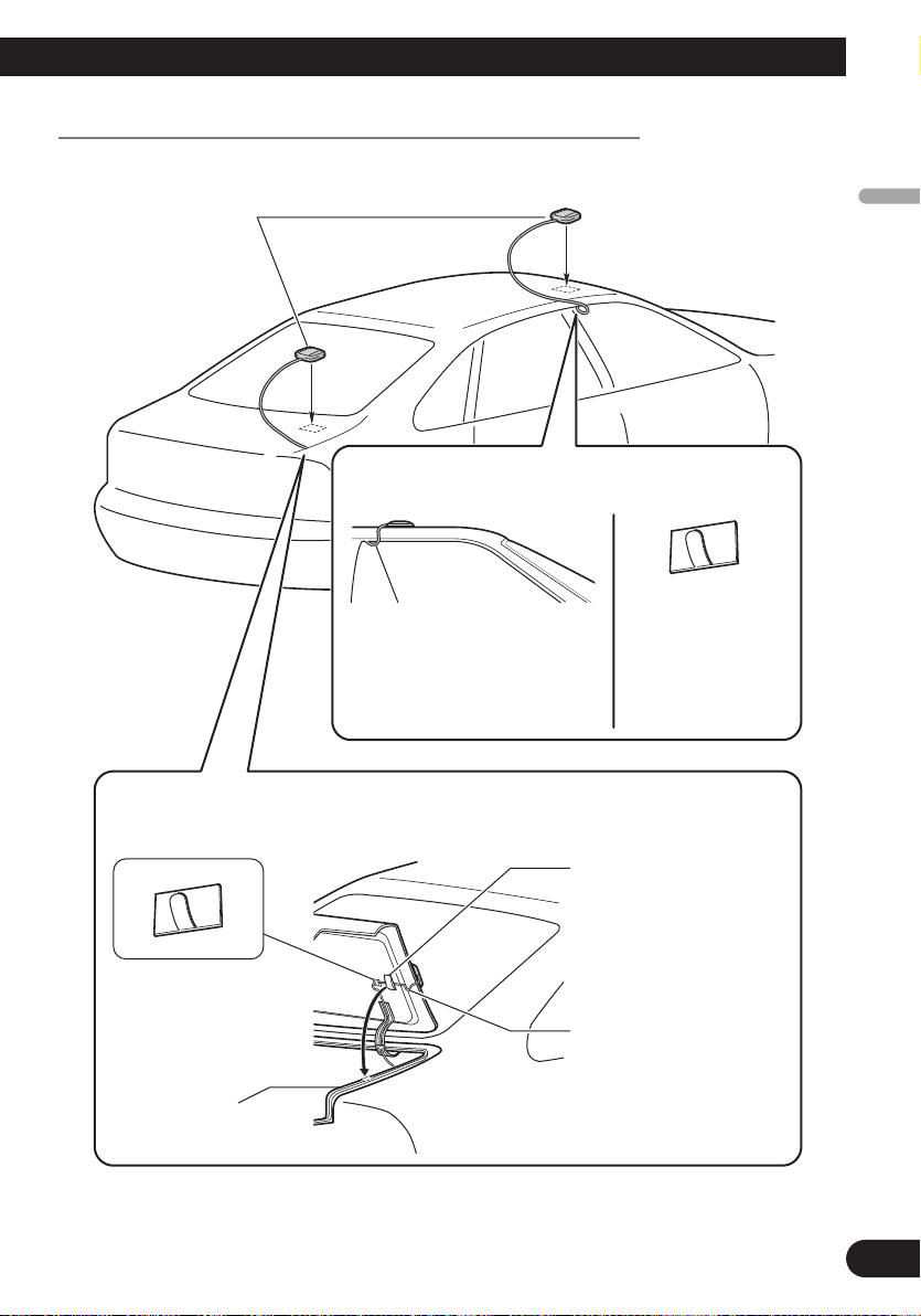
When installing the aerial outside the vehicle (on the body)
Clamps
Use clamps to secure
the lead where
necessary inside the
vehicle.
Clamps
Use clamps to secure the
lead where necessary inside
the vehicle.
GPS aerial
When routing the lead in from the top of the
door
Make a U-shaped loop in the lead
on the outside to prevent rainwater
from flowing along the lead into the
interior of the vehicle.
When routing the lead in from inside the boot
Waterproof pad
Make sure the waterproof pad
contacts the top of the rubber
packing.
Make a U-shaped loop in the
lead outside the rubber
packing to prevent rainwater
from flowing along the lead
into the interior of the vehicle.
Rubber packing
Put the GPS aerial in a position as level as possible, such as on the roof or boot lid. (The
GPS aerial is fastened with a magnet.)
English
Español
Deutsch
Français
Italiano
Nederlands
28
After Installing the Unit
1. Reconnecting the battery.
First, double-check that all connections are correct and that the unit is installed correctly.
Reassemble all vehicle components that you previously removed. Then reconnect the negative (–) cable to the negative (–) terminal of the battery.
2. Start the engine.
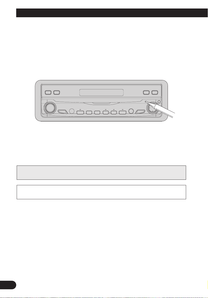
3. Press the RESET button on the display unit.
Press the RESET button on the display unit using a pointed object such as the tip of a pen.
4. Enter the following settings:
• Install the programme in the navigation system.
• Drive until the initialised sensors start operating normally.
• Set the time and language.
Set the navigation system as explained in the “Operation Manual” or “Hardware Manual”.
Note:
If you reconnected the Hide-away unit, press the RESET button.
After installing the unit, be sure to check at a safe place that the vehicle is performing
normally.
29
 Loading...