


INSTALLATION MANUAL
AVH-P5000DVD
|
English |
MANUEL |
Deutsch Español |
D’INSTALLATION |
PyТТНЛИ Nederlands Italiano Français |
|
|

Contents |
|
Connecting the Units |
|
|
|
Connecting the Units ................................ |
1 |
Parts supplied .................................................... |
3 |
Connecting the power cord .............................. |
5 |
When connecting to separately sold power |
|
amp ............................................................ |
7 |
When connecting with a rear view camera ...... |
9 |
When connecting with a multi-channel |
|
processor .................................................. |
10 |
Connecting and installing the optical cable |
|
connection box ........................................ |
11 |
When connecting the external video |
|
component and the display ...................... |
12 |
Installation ................................................ |
13 |
DIN Front/Rear-mount .................................... |
13 |
DIN Front-mount ............................................ |
14 |
DIN Rear-mount .............................................. |
15 |
Fastening the front panel ................................ |
16 |
 WARNING
•To avoid the risk of accident and the potential violation of applicable laws, the front DVD or TV (sold separately) feature should never be used while the vehicle is being driven. Also, Rear Displays should not be in a location where it is a visible distraction to the driver.
•In some countries or states the viewing of images on a display inside a vehicle even by persons other than the driver may be illegal. Where such regulations apply, they must be obeyed and this unit’s DVD features should not be used.
CAUTION
•PIONEER does not recommend that you install or service your display yourself. Installing or servicing the product may expose you to risk of electric shock or other hazards. Refer all installation and servicing of your display to authorized Pioneer service personnel.
•Secure all wiring with cable clamps or electrical tape. Do not allow any bare wiring to remain exposed.
•Do not drill a hole into the engine compartment to connect the yellow lead of the unit to the vehicle battery. Engine vibration may eventually cause the insulation to fail at the point where the wire passes from the passenger compartment into the engine compartment. Take extra care in securing the wire at this point.
•It is extremely dangerous to allow the display lead to become wound around the steering column or gearshift. Be sure to install the display in such a way that it will not obstruct driving.
•Make sure that wires will not interfere with moving parts of the vehicle, such as the gearshift, parking brake or seat sliding mechanism.
•Do not shorten any leads. If you do, the protection circuit may fail to work properly.
 WARNING
LIGHT GREEN LEAD AT POWER CONNECTOR IS DESIGNED TO DETECT PARKED STATUS AND MUST BE CONNECTED TO THE POWER SUPPLY SIDE OF THE PARKING BRAKE SWITCH. IMPROPER CONNECTION OR USE OF THIS LEAD MAY VIOLATE APPLICABLE LAW AND MAY RESULT IN SERIOUS INJURY OR DAMAGE.
1

Note:
•This unit cannot be installed in a vehicle without ACC (accessory) position on the ignition switch.
|
|
CC |
|
|
|
|
|
|
|
|
|
F |
A |
O |
|
|
|
F |
O |
|
|
|
|
N |
|
N |
||||||
O |
F |
|
|
|
|
O |
F |
|
|
|
|
|
|
|
S |
|
|
|
S |
||
|
|
|
|
|
|
|
|
|
||
|
|
|
|
|
T |
|
|
|
|
T |
|
|
|
|
R |
A |
|
|
|
R |
A |
|
|
|
T |
|
|
|
T |
|
||
ACC position |
No ACC position |
|||||||||
•Use this unit in other than the following conditions could result in fire or malfunction.
—Vehicles with a 12-volt battery and negative grounding.
—Speakers with 50 W (output value) and 4 ohm to 8 ohm (impedance value).
•To prevent short-circuit, overheating or malfunction, be sure to follow the directions below.
—Disconnect the negative terminal of the battery before installation.
—Secure the wiring with cable clamps or adhesive tape. To protect the wiring, wrap adhesive tape around them where they lie against metal parts.
—Place all cables away from moving parts, such as gear shift and seat rails.
—Place all cables away from hot places, such as near the heater outlet.
—Do not pass the yellow cable through a hole into the engine compartment to connect to a battery.
—Cover any disconnected cable connectors with insulating tape.
—Do not remove RCA caps if RCA cables are not used.
—Do not shorten any cables.
—Never cut the insulation of the power cable of this unit in order to share the power to other equipment. Current capacity of the cable is limited.
—Use a fuse of the rating prescribed.
—Never wire the speaker negative cable directly to ground.
—Never band together multiple speaker’s nega-
tive cables.
•Control signal is output through blue/white cable when this unit is powered on. Connect it to an external power amp’s system remote control or the vehicle’s auto-antenna relay control terminal (max. 300 mA, 12 V DC). If the vehicle is equipped with a glass antenna, connect it to the antenna booster power supply terminal.
•Never connect blue/white cable to external power amp’s power terminal. Also, never connect it to the power terminal of the auto antenna. Otherwise, battery drain or malfunction may result.
•IP-BUS connectors are color-coded. Be sure to connect connectors of the same color.
•Black cable is ground. This cable and other product’s ground cable (especially, high-current products such as power amp) must be wired separately. Otherwise, fire or malfunction may result if they are accidentally detached.
PyТТНЛИ Nederlands Italiano Franзais Deutsch Espaсol English
2
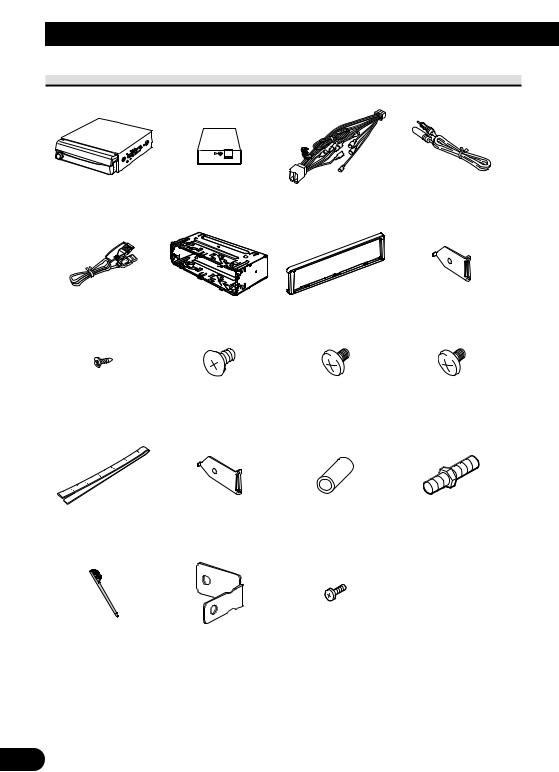
Connecting the Units
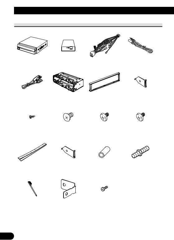
Parts supplied
This product |
Tuner box |
Power cord |
Antenna cable |
USB cable |
Mounting sleeve |
Trim ring |
Side bracket (small) |
|
(pre-installed) |
(pre-installed) |
(2 pcs.) (pre-installed) |
||
|
Screw (2 mm × 3 mm) |
Flush surface screw |
Binding screw |
Binding screw |
(5 mm × 6 mm) (6 pcs.) |
(5 mm × 6 mm) |
(4 mm × 3 mm) |
|
(4 pcs.) (pre-installed) |
(2 are pre-installed.) |
(4 pcs.) |
(4 pcs.) |
|
Concealing tape |
Side bracket (large) |
Rubber bush |
Double-ended screw |
|
(2 pcs.) |
||||
|
|
|
Touch panel pen Holder ×
Screw
(2 mm 5 mm) (2 pcs.)
3

English |
Español |
Deutsch |
Français |
Italiano |
Nederlands |
PyТТНЛИ |
4
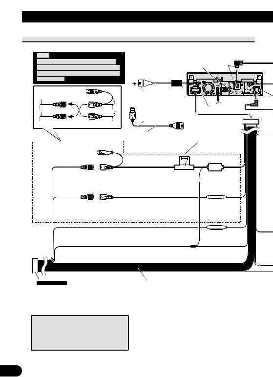
Connecting the Units
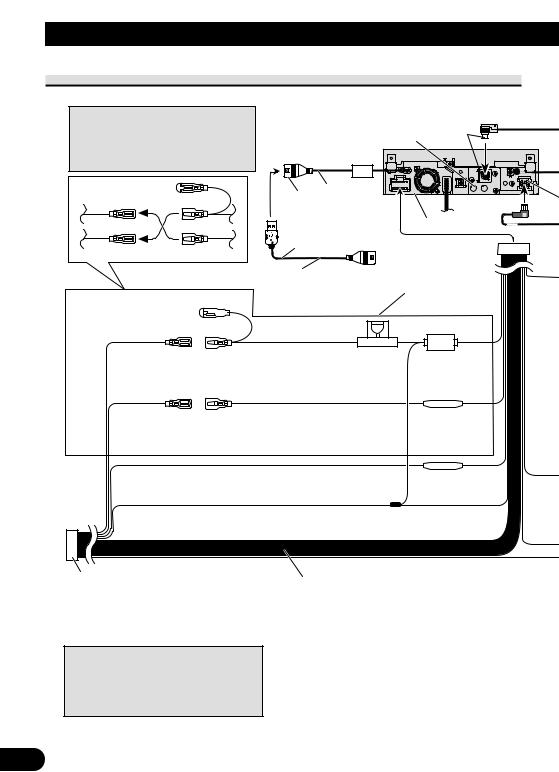
Connecting the power cord
Note:
Depending on the kind of vehicle, the function of 3* and 5* may be different. In this case, be sure to connect 2* to 5* and 4* to 3*.
1*
3* 2*
5* 4*
Cap (1*)
Do not remove cap if this
 terminal is not in use.
Wired remote input
Hard-wired remote control adaptor Gray can be connected (sold separately).
 20 cm
20 cm
USB input |
|
|
|
|
|
This product |
|
|
|
|
|
|
|
|
1.5 m |
|
|
|
|
USB cable (supplied) |
Connect leads of the same |
|
|
|
|
|
|
||
Connect to separately sold |
color to each other. |
|
|
|
USB device. |
|
|
|
|
Yellow (3*) |
Yellow (2*) |
Fuse (10 A) |
||||||
Back-up |
Connect to the constant 12 V |
|
||||||
(or accessory) |
supply terminal. |
|
||||||
|
|
|
|
|
|
|
|
|
|
|
|
|
|
|
|
|
|
Red (5*) |
Red (4*) |
|
||||||
Accessory |
Connect to terminal controlled by |
|
||||||
(or back-up) |
ignition switch (12 V DC). |
|
||||||
Orange/white
Connect to lighting switch terminal.
Black (chassis ground)
Connect to a clean, paint-free metal location.
Fuse resistor
Fuse resistor
Note:
In some vehicles, the ISO connector may be divided into two. In this case, be sure to connect to both connectors.
When you connect the separately sold multichannel processor (e.g., DEQ-P6600) to this unit, do not connect anything to the speaker leads and system remote control (blue/white).
Speaker leads |
|
White: |
Front left + |
White/black: |
Front left ≠ |
Gray: |
Front right + |
Gray/black: |
Front right ≠ |
Green: |
Rear left + or subwoofer + |
Green/black: |
Rear left ≠ or subwoofer ≠ |
Violet: |
Rear right + or subwoofer + |
Violet/black: |
Rear right ≠ or subwoofer ≠ |
5
|
|
|
|
|
|
|
|
|
|
|
|
|
|
|
|
|
|
|
|
|
|
|
|
|
|
Dock connector |
|||||||
|
|
|
|
|
|
|
|
|
Connect to separately sold iPod. |
|||||||
|
|
Interface cable (e.g., CD-I200) |
|
|
|
|
|
|
|
|
||||||
|
|
(sold separately) |
|
|
|
|
|
|
|
|
80 cm |
|||||
|
|
|
|
|
|
|
80 cm |
|
|
|
|
Tuner box (supplied) |
||||
|
|
|
|
|
|
|
|
|
|
|
|
|
||||
IP-BUS input |
|
IP-BUS cable |
|
|
|
|
|
|
|
|
|
|
|
|||
|
|
|
|
|
|
|
|
|
|
|||||||
(Blue) |
|
|
|
|
|
Multi-CD player |
|
|
|
|
|
|
|
|
|
|
|
|
|
|
|
|
|
(sold separately) |
|
|
|
|
|
|
|
|
|
Yellow/black |
|
|
|
|
|
|
|
|
|
Antenna cable |
||||||
|
|
|
|
|
|
|
|
|
|
|
||||||
|
|
|
|
|
|
|
|
|
|
|
||||||
|
|
|
|
|
|
|
|
|
|
|
|
|
|
|
||
If you use an equipment with Mute function, wire this lead to the Audio Mute lead on (supplied) |
||||||||||||||||
that piece of equipment. If not, keep the Audio Mute lead free of any connections. |
||||||||||||||||
|
|
|
|
|
|
|
|
|
|
|
|
|
|
|
|
|
|
Connection method |
|
|
|
|
|
|
|
|
|
|
|||||
|
|
|
|
|
|
|
|
|
|
|
|
|
|
|
||
|
|
|
1. |
Clamp the lead. |
|
|
|
|
2. |
|
Clamp firmly with |
|||||
|
|
|
|
|
|
|
|
|
|
|
|
|
|
|
||
|
|
|
|
|
|
|
|
|
|
|
|
needle-nosed pliers. |
||||
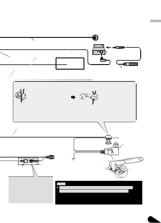
Note:
 The position of the parking brake switch depends on the vehicle model. For details, consult the vehicle Owner
  s Manual or dealer.
Light green
Used to detect the ON/OFF status of the parking brake. This lead must be connected to the power supply side of the parking brake switch.
Blue/white
Connect to system control terminal of the power Power supply side amp (max. 300 mA 12 V DC).
|
|
|
|
|
|
|
|
|
|
|
|
|
|
|
Ground side |
|
|
|
|
|
|
|
|
|
|
Blue/white (7*) |
|||||
|
|
|
|
|
|
|
|
|
|
||||||
Blue/white (6*) |
|
Connect to auto-antenna relay control terminal |
|||||||||||||
|
|
|
|
|
|
|
|
|
|
(max. 300 mA 12 V DC). |
|||||
Parking brake switch
The pin position of the ISO connector will differ depending on the type of vehicle. Connect 6* and 7* when Pin 5 is an antenna control type. In other types of vehicles, never connect 6* and 7*.
Notes:
Change the initial setting of this unit (refer to the Operation Manual). The subwoofer output of this unit is monaural.
•When using a subwoofer of 70 W (2 Ω) , be sure to connect with Violet and Violet/black leads of this unit. Do not connect anything to Green and Green/black leads.
PyТТНЛИ Nederlands Italiano Franзais Deutsch Espaсol English
6
Connecting the Units
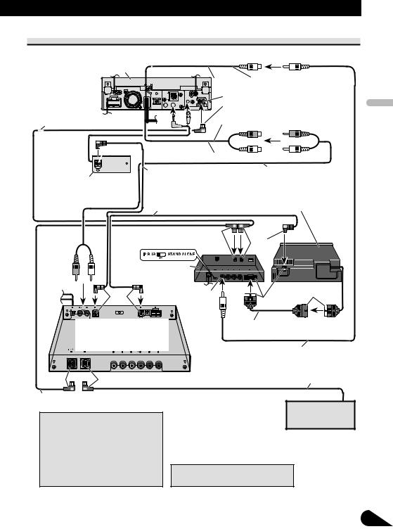
When connecting to separately sold power amp
This product
Rear output or subwoofer output (REAR/SUBWOOFER/DEQ OUTPUT)
15 cm
Front output
 (FRONT OUTPUT) 15 cm
Blue/white
Connect to system control terminal of the power amp (max. 300 mA 12 V DC).
|
Blue/white (7*) |
Blue/white (6*) |
Connect to auto-antenna relay control terminal |
|
(max. 300 mA 12 V DC). |
The pin position of the ISO connector will differ depending on the type of vehicle. Connect 6* and 7* when Pin 5 is an antenna control type. In other types of vehicles, never connect 6* and 7*.
When you connect the separately sold multichannel processor (e.g., DEQ-P6600) to this unit, do not connect anything to the speaker leads and system remote control (blue/white).
When you connect the multi-channel processor to this unit, refer to multi-channel processor’s installation manual for the connection method.
7
Power amp (sold separately)
Power amp (sold separately)
Connect with RCA cables (sold separately)
System remote control
Left |
Right |
++
Front speaker |
|
Front speaker |
≠≠
Rear speaker |
+ |
+ |
|
Rear speaker |
|
or subwoofer |
|
≠ |
≠ |
|
or subwoofer |
|
|
||||
|
|
|
|
||
 Perform these connections when using the optional amplifier.
Note:
Change the initial setting of this unit (refer to the Operation Manual). The subwoofer output of this unit is monaural.
PyТТНЛИ Nederlands Italiano Franзais Deutsch Espaсol English
8
Connecting the Units
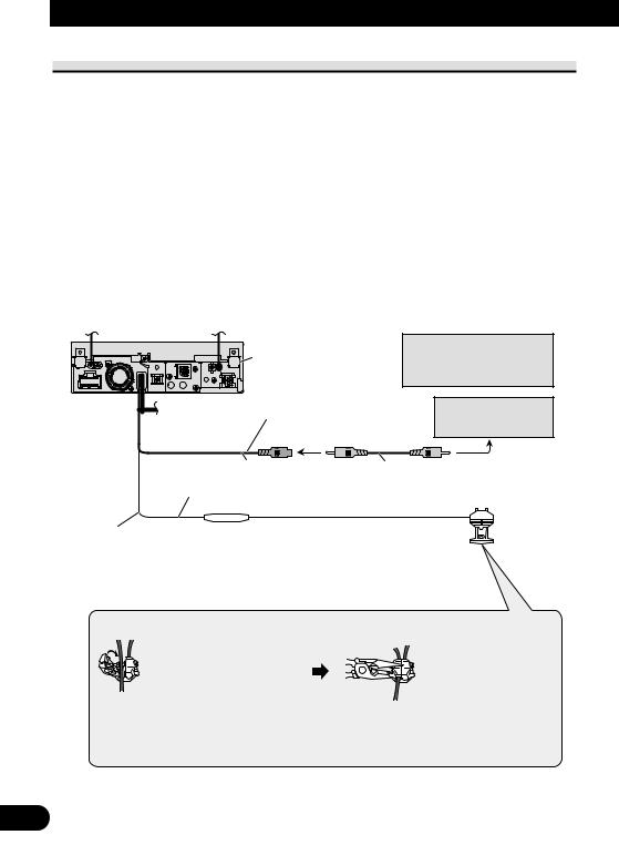
When connecting with a rear view camera
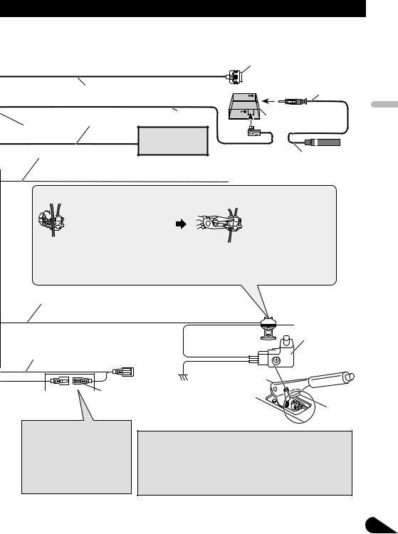
When this product is used with a rear view camera, it is possible to automatically switch from the video to rear view image when the gear shift is moved to REVERSE (R).
 WARNING
USE INPUT ONLY FOR REVERSE OR MIRROR IMAGE REAR VIEW CAMERA. OTHER USE MAY RESULT IN INJURY OR DAMAGE.
 CAUTION
•The screen image may appear reversed.
•The rear view camera function is to be used as an aid for backing into a tight parking spot. Do not use this function for entertainment purposes.
•Objects in the rear view may appear closer or more distant than they actually are.


 This product
Rear view camera input (REAR VIEW CAMERA IN)
 CAUTION
You must use a camera which outputs mirror reversed images.
Rear view camera
|
|
|
|
|
|
To video output |
20 cm |
|
RCA cable |
||||
|
|
|
(sold separately) |
|
||
15 cm
Violet/white
Of the two lead wires connected to the back lamp, connect the one in which the voltage changes when the gear shift is in the REVERSE (R) position. This connection enables the unit to sense whether the car is moving forwards or backwards.
Connection method
1. Clamp the lead.
2.Clamp firmly with needle-nosed pliers.
Note:
 It is necessary to set CAMERA POLARITY properly in SYSTEM MENU when connecting the rear view camera.
9

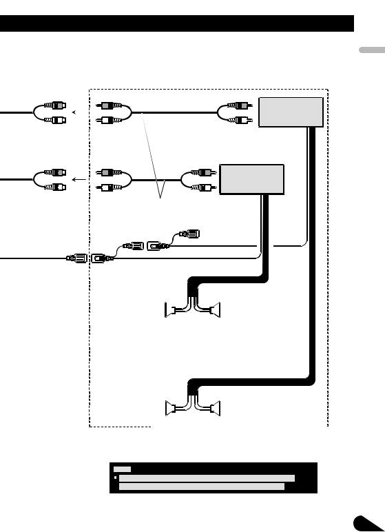
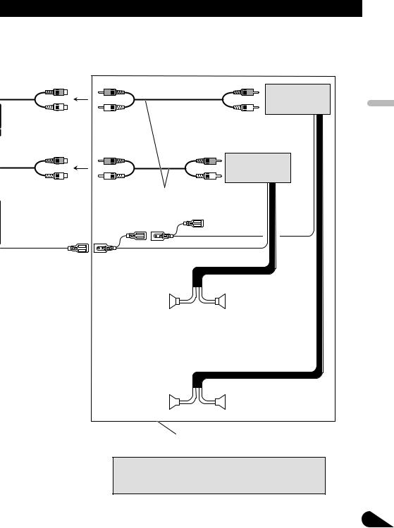
When connecting with a multi-channel processor
This product |
|
25 cm |
Video input |
|
(VIDEO INPUT) |
IP-BUS cable |
IP-BUS input (Blue) |
|
Blue |
||
(supplied with DVD |
DEQ output (REAR/ |
|
player) |
||
SUBWOOFER/DEQ OUTPUT) |
||
|
 Black
Black
15 cm |
|
Optical cable (supplied with |
RCA cable (supplied with |
|
Optical cable connection box |
multi-channel processor) |
multi-channel processor) |
(supplied with multi-channel |
|
|
processor) |
Optical cable (sold |
DVD player (e.g., XDV-P6) |
|
||
|
separately) |
(sold separately) |
Blue
Black
Hide-away unit (supplied  with DVD player)
Blue
Front video output (Yellow)
Multi-channel processor (e.g., DEQ-P6600) (sold separately)
Black |
Blue |
Black
Black
25 pin cable (supplied with DVD player)
RCA cable (supplied with DVD player)
IP-BUS cable
IP-BUS cable (supplied with multi-channel processor)
When you connect a separately sold DVD player to the separately sold multi-channel processor, the optical cable from DVD player must be connected to the optical cable 2 input (OPT. IN2) of the multi-channel processor.
Multi-CD player (sold separately)
You can use only one video component with this unit.
PyТТНЛИ Nederlands Italiano Franзais Deutsch Espaсol English
10
Connecting the Units
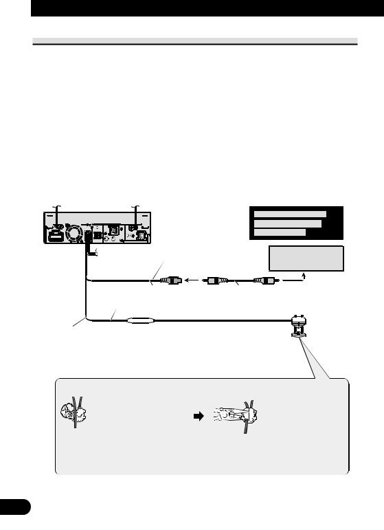
Connecting and installing the optical cable connection box
 WARNING
•Avoid installing this unit in locations where the operation of safety devices such as airbags is prevented by this unit. Otherwise, there is a danger of a fatal accident.
•Avoid installing this unit in locations where the operation of the brake may be prevented. Otherwise, it may result in a traffic accident.
•Fix this unit securely with the hook and loop fastener or lock tie. If this unit is loose, it disturbs driving stability, which may result in a traffic accident.
 CAUTION
•Install this unit using only the parts supplied with this unit. If other parts are used, this unit may be damaged or could dismount itself, which leads to an accident or other problems.
•Do not install this unit near the doors where rainwater is likely to be spilled on the unit. Incursion of water into the unit may cause smoke or fire.
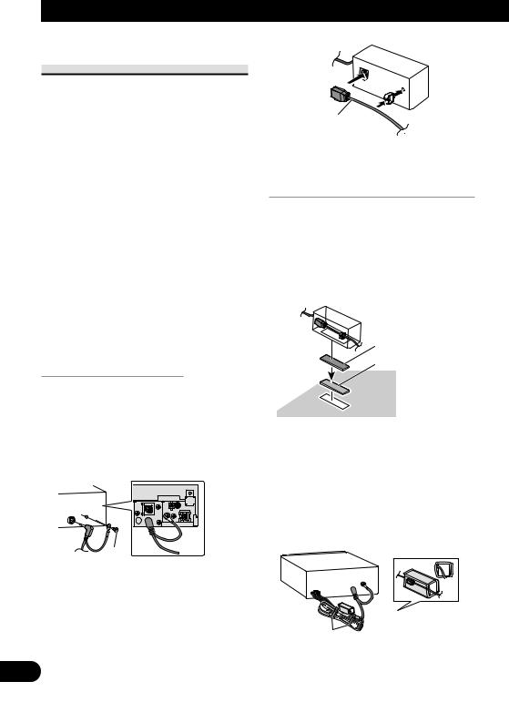
Connecting the optical cable
1.Connect the optical cable and ground lead to the main unit.
Connect the optical cable so that it does not protrude from the unit, as shown in the illustration. Fasten the ground lead to the protrusion on the back of the unit.
Screw
2.Connect the optical cable to the optical cable connection box.
Optical cable
Installing the optical cable connection box
•When installing the optical cable connection box with the hook and loop fastener.
Install the optical cable connection box using the hook and loop fastener in the ample space of the console box.
Hook fastener
 Loop fastener
•When installing the optical cable connection box with the lock tie.
Wrap the optical cable and connection box with the protection tape and fasten with the power code using the lock tie.
Wrap with the protection tape
Fasten with the lock tie
11
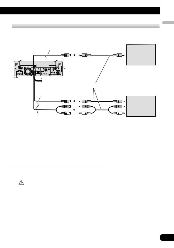
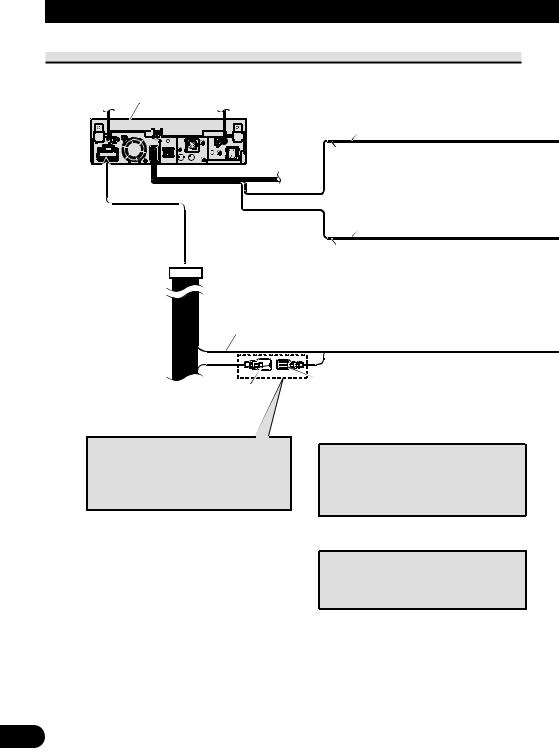
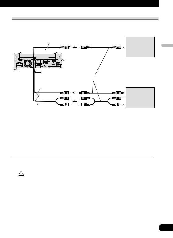
When connecting the external video component and the display
Rear monitor output
(REAR MONITOR OUTPUT)
 20 cm
20 cm
This product |
To video input |
Display with |
||||
|
|
|
|
|
RCA input jacks |
|
|
|
|
|
(sold separately) |
|
RCA cables (sold separately) |
|
Video input |
|
|
(VIDEO INPUT) |
To video output |
|
|
||
25 cm |
External video |
|
component |
||
|
(sold separately) |
|
Audio input |
To audio outputs |
|
(AUDIO INPUT) |
||
|
•It is necessary to set AV INPUT to VIDEO in SYSTEM MENU when connecting the external video component.
•It is necessary to set AV INPUT to S-DVD in SYSTEM MENU when connecting a multi-DVD player.
When using a display connected to rear video output
This product’s rear video output is for connection of a display to enable passengers in the rear seats to watch the DVD or Video CD.
WARNING
•NEVER install the display in a location that enables the Driver to watch the DVD or Video CD while driving.
PyТТНЛИ Nederlands Italiano Franзais Deutsch Espaсol English
12
Installation
Note:
•Check all connections and systems before final installation.
•Do not use unauthorized parts. The use of unauthorized parts may cause malfunctions.
•Consult with your dealer if installation requires drilling of holes or other modifications of the vehicle.
•Do not install this unit where:
—it may interfere with operation of the vehicle.
—it may cause injury to a passenger as a result of a sudden stop.
•Do not install the display where it may (i) obstruct the driver’s vision, (ii) impair the performance of any of the vehicle’s operating systems or safety features, including air bags, hazard lamp buttons or (iii) impair the driver’s ability to safely operate the vehicle.
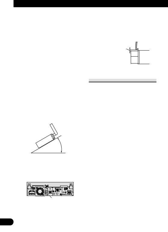
•The semiconductor laser will be damaged if it overheats. Install this unit away from hot places such as near the heater outlet.
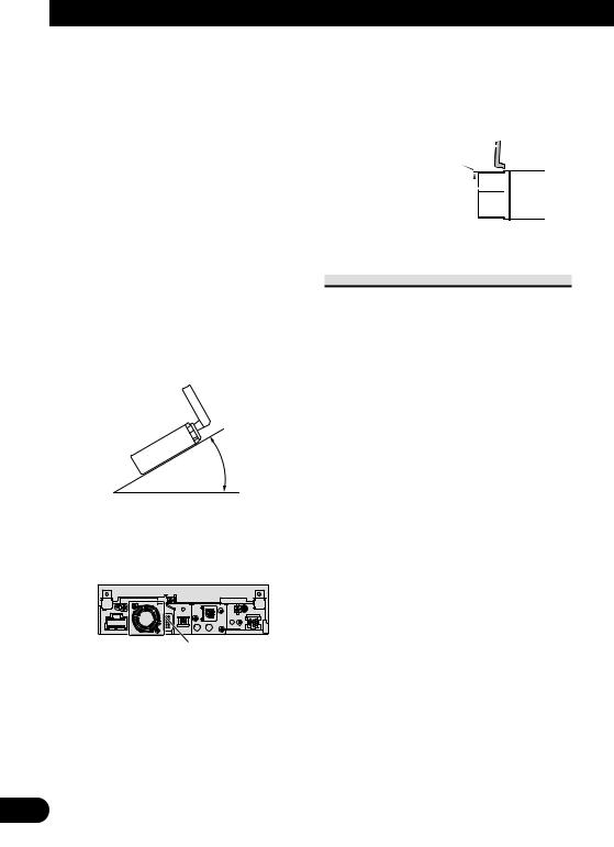
•Optimum performance is obtained when the unit is installed at an angle of less than 30°.
30°
•The cords must not cover up the area shown in the figure below. This is necessary to allow the amplifires to radiate freely.
Do not cover this area.
•Make sure you leave enough gap between the dashboard and the LCD panel of this unit so the LCD panel can be opened and closed without contacting with the dashboard.
Dashboard
Leave gap
LCD panel
DIN Front/Rear-mount
This unit can be properly installed either from “Front” (conventional DIN Front-mount) or “Rear” (DIN Rearmount installation, utilizing threaded screw holes at the sides of unit chassis). For details, refer to the following illustrated installation methods.
13
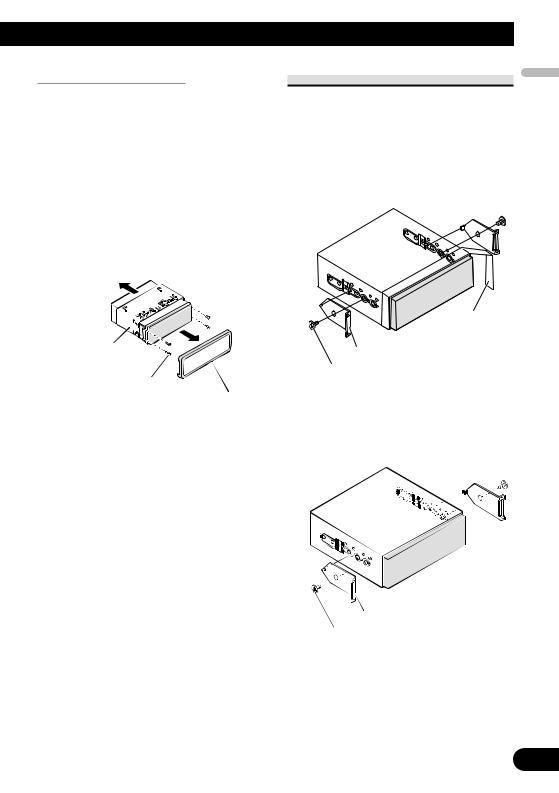
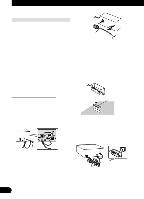
Before installing the unit
•Remove the trim ring and the mounting sleeve.
Extend top and bottom of the trim ring
outwards to remove the trim ring. And then loosen the screws (2 mm × 3 mm) to remove the mounting sleeve.
•When reattaching the trim ring, push the trim ring onto the unit until it clicks after reattaching the mounting sleeve. (If the trim ring is attached upside down, the trim ring will not fit properly.)
Mounting sleeve
Screw (2 mm × 3 mm)
Trim ring
DIN Front-mount
brackets. |
|
English |
|
1. Decide the position of the side |
|
||
• When installing in a shallow space, |
|
||
change the position of side brackets |
|
||
(small). In this case, stick concealing |
|
||
tape on parts that protrude from the |
Español |
||
dashboard. |
|
||
|
|
||
Concealing tape |
Deutsch |
||
|
|||
Side bracket (small) |
|
|
|
Flush surface screw (5 mm × 6 mm) |
Français |
||
• If you prefer an off-set installation |
|||
|
|||
in which the front panel is pushed |
|
||
further back, when there is a space |
|
||
available at the back of the unit, use |
|
||
the side brackets (large). |
|
|
|
|
|
Italiano |
|
Side bracket (large) |
|
Nederlands |
|
|
|
||
Flush surface screw (5 mm |
6 mm) |
|
|
|
|
PyТТНЛИ |
|
14
Installation
2.Install the unit into the dashboard.
Insert the mounting sleeve into the dashboard. And then secure the mounting sleeve by using a screwdriver to bend the metal tabs (90°) into place.
Dashboard
182
53 |
Rubber bush |
|
|
|
Screw |
Mounting sleeve
Side bracket 


Screw (2 mm × 3 mm)
DIN Rear-mount
1.Determine the appropriate position where the holes on the bracket and the side of the unit
match.
*1 Use binding screws (4 mm × 3 mm) only.
*1
*1
•When installing in a shallow space, use the following screw holes. In this case, stick concealing tape on parts that protrude from the dashboard.
*1
*1
Concealing tape
15
2.Tighten two screws on each side.
Use any of binding screws (4 mm × 3 mm), binding screws (5 mm × 6 mm) or flush surface screws (5 mm × 6 mm), depending on the shape of screw holes in the bracket.
Screw
Dashboard or Console
Factory radio mounting bracket
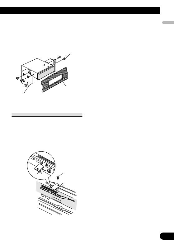
Fastening the front panel
If you do not plan to detach the front panel, the front panel can be fastened with supplied screws and holder.
•Fix the front panel to the unit using screws and holder after removing the trim ring.
Screw
 Screw
Screw
Holder
PyТТНЛИ Nederlands Italiano Franзais Deutsch Espaсol English
16

Contenido |
|
Conexión de las unidades |
|
|
|
Conexión de las unidades ........................ |
1 |
Piezas suministradas .......................................... |
3 |
Conexión del cable de alimentación .................. |
5 |
Cuando conecte a un amplificador de |
|
potencia vendido separadamente ................ |
7 |
Cuando conecte con una cámara de |
|
vista trasera ................................................ |
9 |
Cuando conecte con un procesador |
|
multicanal ................................................ |
10 |
Conexión e instalación de la caja de conexión |
|
de cable óptico .......................................... |
11 |
Cuando conecte el componente externo y |
|
la pantalla ................................................ |
12 |
Instalación ................................................ |
13 |
Montaje delantero/trasero DIN ........................ |
13 |
Montaje delantero DIN .................................... |
14 |
Montaje trasero DIN ........................................ |
15 |
Fijación del panel delantero ............................ |
16 |
 ADVERTENCIA
•Para evitar el riesgo de accidentes e violación potencial de las leyes aplicables, no se debe usar nunca la función de DVD o TV frontal (vendido separadamente) mientras el vehículo esté siendo conducido. Igualmente, los monitores traseros no deben quedarse en un sitio donde puedan causar una distracción visible al conductor.
•En algunos países o estados, puede ser ilícita la visualización de imágenes en un display dentro de un vehículo, incluso por otras personas que no sean el conductor. En los casos en que resulten aplicables, estas normas deben respetarse y no deben usarse las funciones de DVD de esta unidad.
PRECAUCIÓN
•PIONEER no recomienda que sea usted mismo quien instale o revise su pantalla. La instalación o revisión del producto puede exponerle a descargas eléctricas u otros peligros. Solicite que todos los trabajos de instalación y revisión de su pantalla los realice el personal de servicio Pioneer autorizado.
•Asegure todo el cableado con abrazaderas de cables o cinta para usos eléctricos. No permita que el cableado pelado permanezca expuesto.
•No taladre un agujero en el compartimiento del motor para conectar el cable amarillo de la unidad a la batería del vehículo. La vibración del motor podría estropear el aislamiento en el punto por donde el cable pasa del compartimiento de los pasajeros al compartimiento del motor. Tenga mucho cuidado para mantener el buen estado del cable en lo relativo a este punto.
•Es peligrosísimo dejar que el cable de la pantalla se enrolle en la base del volante o en la palanca de cambios. Asegúrese de instalar la pantalla de forma que ésta no sea un obstáculo para la conducción.
•Asegúrese de que los cables no interfieran con partes móviles del vehículo tales como la palanca de cambio, el freno de mano o el mecanismo de deslizamiento de los asientos.
•No acorte ningún cable. Si lo hace, el circuito de protección tal vez no funcione correctamente.
 ADVERTENCIA
EL CABLE VERDE CLARO DEL CONECTOR DE ALIMENTACIÓN ESTÁ DISEÑADO PARA DETECTAR SI EL VEHÍCULO ESTÁ ESTACIONADO Y DEBE CONECTARSE CON EL LADO DE LA FUENTE DE ALIMENTACIÓN DEL INTERRUPTOR DEL FRENO DE MANO. LA CONEXIÓN O EL USO INCORRECTO DE ESTE CABLE PUEDE INFRINGIR LAS LEYES PERTINENTES Y OCASIONAR LESIONES FÍSICAS O DAÑOS GRAVES.
1

Nota:
•No se puede instalar esta unidad en un vehículo sin una posición ACC (accesorio) en el interruptor de encendido.
|
|
CC |
|
|
|
|
|
|
|
|
|
F |
A |
O |
|
|
|
F |
O |
|
|
|
|
N |
|
N |
||||||
O |
F |
|
|
|
|
O |
F |
|
|
|
|
|
|
|
S |
|
|
|
S |
||
|
|
|
|
|
|
|
|
|
||
|
|
|
|
|
T |
|
|
|
|
T |
|
|
|
|
R |
A |
|
|
|
R |
A |
|
|
|
T |
|
|
|
T |
|
||
Posición ACC |
Sin posición ACC |
|||||||||
•El uso de esta unidad en condiciones diferentes de las siguientes podría causar un fuego o fallo de funcionamiento.
—Vehículos con una batería de 12 voltios y puesta a tierra negativa.
—Altavoz con 50 W (valor de salida) y de 4 a 8 ohmios (valor de impedancia).
•Para prevenir cortocircuitos, sobrecalentamiento o fallo de funcionamiento, asegúrese de seguir las instrucciones a continuación.
—Desenchufe el terminal negativo de la batería antes de la instalación.
—Fije el cableado con abrazaderas de cable o con cinta adhesiva. Para proteger el cableado, envuélvalo con cinta adhesiva donde el cableado se apoya sobre piezas metálicas.
—Posicione todos los cables alejados de las piezas móviles, como el cambio de marchas y rieles de los asientos.
—Posicione todos los cables alejados de lugares calientes como cerca de la salida del calentador.
—No pase el cable amarillo a través de un agujero en el compartimiento del motor para conectar la batería.
—Cubra cualquier conector de cable desconectado con cinta de aislamiento.
—No extraiga las tapas RCA si no se utilizan los cables RCA.
—No acorte ningún cable.
—No corte nunca el aislamiento del cable de alimentación de esta unidad para compartir la energía con otro equipo. La capacidad de corriente del cable es limitada.
—Utilice un fusible con la capacidad especificada.
—No conecte nunca el cable negativo de altavoz directamente a la puesta a tierra.
—No junte nunca múltiples cables negativos de
altavoz.
•La señal de control se emite a través del cable azul/blanco cuando se enciende esta unidad. Conéctelo a un terminal de control de sistema de amplificador de potencia externo o al terminal de control de relé de antena automática del vehículo (máx. 300 mA, 12 V CC). Si el vehículo está equipado con una antena de vidrio, conéctelo al terminal de suministro de potencia de refuerzo de la antena.
•No conecte nunca el cable azul/blanco al terminal de alimentación de un amplificador de potencia externo. Igualmente, no conéctelo nunca al terminal de alimentación de la antena automática. De lo contrario, puede ocurrir la descarga de la batería o un fallo de funcionamiento.
•Los conectores IP-BUS están codificados en colores. Asegúrese de conectar los conectores del mismo color.
•El cable negro es para la puesta a tierra. Se debe conectar este cable y el cable de puesta a tierra de otro producto (especialmente de productos de alta corriente como un amplificador de potencia) separadamente. De lo contrario, puede ocurrir un fuego o fallo de funcionamiento si los cables se sueltan accidentalmente.
PyТТНЛИ Nederlands Italiano Franзais Deutsch Español English
2
Conexión de las unidades
Piezas suministradas
Este producto |
Caja de sintonizador |
Cable USB
Manguito de montaje (preinstalado)
Tornillo (2 mm × 3 mm) |
Tornillo de cabeza embutida |
(4 piezas) |
(5 mm × 6 mm) (6 piezas) |
(preinstalado) |
(2 piezas preinstaladas.) |
Cable de alimentación |
Cable de antena |
Anillo de |
Ménsula lateral |
compensación |
(pequeña) (2 piezas) |
(preinstalado) |
(preinstalado) |
Tornillo de apriete |
Tornillo de apriete |
(5 mm × 6 mm) |
(4 mm × 3 mm) |
(4 piezas) |
(4 piezas) |
Cinta de |
Ménsula lateral |
Buje de caucho |
Prisionero |
|
encubrimiento |
(grande) (2 piezas) |
|||
|
|
Bolígrafo de panel táctil Sujetador ×
Tornillo
(2 mm 5 mm) (2 piezas)
3
English |
Español |
Deutsch |
Français |
Italiano |
Nederlands |
PyТТНЛИ |
4
Conexión de las unidades
Conexión del cable de alimentación
Nota:
Dependiendo del tipo de vehículo, la función de 3* y 5* puede ser diferente. En este caso, asegúrese de conectar 2* a 5* y 4* a 3*.
1*
3* 2*
5* 4*
Tapa (1*)
No quite la tapa cuando no 
 se utiliza este terminal.
Entrada remota cableada |
|
|
Se puede conectar el adaptador de |
Gris |
|
control remoto cableado (vendido |
|
|
|
|
|
separadamente). |
|
|
20 cm |
|
|
Entrada USB |
|
|
|
Este producto |
|
1,5 m |
|
Cable USB (suministrado) |
Conecte los hilos del |
Conecte al dispositivo USB |
mismo color a cada otro. |
vendido separadamente. |
|
Amarillo (3*) |
Amarillo (2*) |
Fusible (10 A) |
Reserva |
Conecte el terminal de |
|
(o accesorio) |
suministro de 12 V constante. |
|
Rojo (5*) |
Rojo (4*) |
|
Accesorio |
Conecte al terminal controlado por del |
|
(o reserva) |
interruptor de encendido (12 V CC). |
|
Anaranjado/blanco
Conecte al terminal de interruptor de iluminación.
Negro (masa de la carrocería)
Conecte a un punto de metal limpio, libre de pintura.
Resistencia de fusible
Resistencia de fusible
Conector ISO
Nota:
En algunos vehículos, puede que el conector ISO esté dividido en dos. En este caso, asegúrese de conectar a ambos conectores.
Cuando conecte el procesador multicanal (e.g., DEQ-P6600) vendido separadamente a esta unidad, no conecte nada a los conductores de los altavoces y al control remoto del sistema (azul/blanco).
Hilos de altavoz
Blanco: |
Izquierda delantera + |
Blanco/negro: |
Izquierda delantera ≠ |
Gris: |
Derecha delantera + |
Gris/negro: |
Derecha delantera ≠ |
Verde: |
Izquierda trasera + o altavoz de subgraves + |
Verde/negro: |
Izquierda trasera ≠ o altavoz de subgraves ≠ |
Violeta: |
Derecha trasera + o altavoz de subgraves + |
Violeta/negro: |
Derecha trasera ≠ o altavoz de subgraves ≠ |
5
|
|
|
Conector del Dock |
||
|
|
|
Conecte al iPod vendido |
||
|
|
Cable de interfaz (e.g., CD-I200) |
separadamente. |
|
|
|
|
|
|
||
|
|
(vendido separadamente) |
|
80 cm |
|
|
|
80 cm |
Caja de sintonizador |
||
Entrada IP-BUS |
Cable IP-BUS |
||||
(suministrada) |
|||||
|
|
||||
(Azul) |
|
Reproductor de |
|
|
|
|
|
Multi-CD (vendido |
|
|
|
Amarillo/negro |
separadamente) |
|
Cable de antena |
||
|
|
||||
Si se utiliza un equipo con función de silenciamiento, conecte este conductor con |
(suministrado) |
||||
el conductor de silenciamiento de audio en tal parte del equipo. De lo contrario, |
|||||
|
|||||
mantenga el conductor de silenciamiento de audio libre de conexiones. |
|
||||
Método de conexión |
|
|
|||
1. |
|
Apriete el cable. |
2. Apriete firmemente |
||
|
|
|
con alicates de |
||
|
|
|
punta de aguja. |
||
Nota:
•La posición del freno de estacionamiento depende del modelo del vehículo. Para conocer detalles, consulte el manual del propietario del vehículo o a su concesionario.
Verde claro
Se utiliza para detectar el estado ON/OFF del freno de mano. Este cable debe conectarse al lado de alimentación del interruptor del freno de mano.
Azul/blanco |
|
Interruptor |
Conecte al terminal de control de sistema del |
|
|
Lado de alimentación |
del freno de |
|
amplificador de potencia (máx. 300 mA 12 V CC). |
|
mano |
|
Lado de masa |
|
 Azul/blanco (7*)
Azul/blanco (6*) Conecte al terminal de control de relé de antena automática (máx. 300 mA 12 V CC).
La posición de los contactos del conector ISO difiere dependiendo del tipo del vehículo. Conecte 6* y 7* cuando el contacto 5 es del tipo de control de antena. En otros tipos de vehículo, no conecte nunca 6* y 7*.
Notas:
•Cambie el ajuste inicial de esta unidad (refiérase al manual de operación). La salida de altavoz de subgraves de esta unidad es monofónica.
•Cuando utilice un altavoz de subgraves de 70 W (2 Ω), asegúrese de conectarlo con los hilos Violeta y Violeta/negro de esta unidad. No conecte nada a los hilos Verde y Verde/negro.
PyТТНЛИ Nederlands Italiano Franзais Deutsch Español English
6
Conexión de las unidades
Cuando conecte a un amplificador de potencia vendido separadamente
Este producto
Salida trasera o salida de altavoz de subgraves (REAR/SUBWOOFER/DEQ OUTPUT)
15 cm
Salida delantera (FRONT OUTPUT)
15 cm
Azul/blanco
Conecte al terminal de control de sistema del amplificador de potencia (máx. 300 mA 12 V CC).
Azul/blanco (6*)
La posición de los contactos del conector ISO difiere dependiendo del tipo del vehículo. Conecte 6* y 7* cuando el contacto 5 es del tipo de control de antena. En otros tipos de vehículo, no conecte nunca 6* y 7*.
 Azul/blanco (7*)
Conecte al terminal de control de relé de antena automática (máx. 300 mA 12 V CC).
Cuando conecte el procesador multicanal (e.g., DEQ-P6600) vendido separadamente a esta unidad, no conecte nada a los conductores de los altavoces y al control remoto del sistema (azul/blanco).
Cuando conecte el procesador multicanal a esta unidad, consulte el manual de instalación del procesador multicanal para el método de conexión.
7
Amplificador de potencia (vendido separadamente)
Amplificador de potencia (vendido separadamente)
Conecte los cables RCA (vendidos separadamente)
Control remoto de sistema
Izquierda |
Derecha |
+ |
+ |
Altavoz delantero |
Altavoz delantero |
≠ |
≠ |
Altavoz trasero o |
+ |
+ |
|
Altavoz trasero o |
|
|
|
|
|
||
altavoz de subgraves |
|
≠ |
≠ |
|
altavoz de subgraves |
|
|
||||
|
|
|
|
||
Realice estas conexiones cuando utilice el amplificador opcional.
Nota:
•Cambie el ajuste inicial de esta unidad (refiérase al manual de operación). La salida de altavoz de subgraves de esta unidad es monofónica.
PyТТНЛИ Nederlands Italiano Franзais Deutsch Español English
8
Conexión de las unidades
Cuando conecte con una cámara de vista trasera
Cuando se utiliza este producto con una cámara de vista trasera, se puede cambiar automáticamente desde vídeo a imagen de vista trasera cuando se desplaza el cambio de marchas a REVERSE (R).
 ADVERTENCIA
UTILICE SOLAMENTE PARA CÁMARA DE VISTA TRASERA DE IMAGEN INVERTIDA O DE ESPEJO. CUALQUIER OTRO USO PUEDE CAUSAR LESIONES O DAÑOS.
 PRECAUCIÓN
•La imagen de la pantalla puede aparecer invertida.
•Se debe utilizar la función de cámara de vista trasera como un auxilio para estacionar en lugares estrechos. No utilice esta función para propósitos de entretenimiento.
•Los objetos en la vista trasera pueden parecer más cercanos o más distantes de que realmente están.
Este producto |
Entrada para cámara de vista trasera (REAR VIEW CAMERA IN)
 PRECAUCIÓN
Se debe utilizar una cámara que genere imágenes invertidas de espejo.
Cámara de vista trasera
|
|
|
|
|
|
|
|
|
A la salida de vídeo |
20 cm |
|
|
|
|
|
|
|||
|
Cable RCA (vendido |
||||||||
|
|
|
|
||||||
|
|
|
|
separadamente) |
|||||
Violeta/blanco
De los dos conductores conectados a la lámpara trasera, conecte el conductor cuyo voltaje cambia cuando se desplaza la palanca de cambio de marcha a la posición REVERSE (R). Esta conexión permite que la unidad detecte si el vehículo está se moviendo hacia delante o hacia atrás.
Método de conexión |
|
1. Apriete el cable. |
2. Apriete firmemente |
|
con alicates de |
|
punta de aguja. |
Nota:
•Se requiere ajustar CAMERA POLARITY adecuadamente en el menú SYSTEM MENU cuando conecte la cámara de vista trasera.
9
Cuando conecte con un procesador multicanal |
|
||
Este producto |
|
|
|
|
25 cm |
Entrada de vídeo |
|
|
|
(VIDEO INPUT) |
|
Cable IP-BUS |
Entrada IP-BUS (Azul) |
||
Azul |
|
||
(suministrado con el |
|
||
Salida DEQ (REAR/ |
|||
reproductor de DVD) |
|||
SUBWOOFER/DEQ OUTPUT) |
|||
|
|||
 Negro
Negro
15 cm |
|
Cable óptico (suministrado |
Cable RCA (suministrado |
|
Caja de conexión de cable |
con el procesador multicanal) |
con el procesador |
|
óptico (suministrada con el |
|
|
multicanal) |
procesador multicanal) |
Cable óptico |
Reproductor de DVD (e.g., XDV-P6) |
|
|
(vendido separadamente) (vendido separadamente) |
||
|
Azul |
|
|
|
|
|
Negro |
Unidad oculta-alejada |
|
|
|
(suministrada con el |
|
|
|
reproductor de DVD) |
|
|
|
Azul |
Salida de vídeo |
|
Negro |
delantera (amarillo) |
|
||
|
Negro |
||
|
|
||
|
|
|
|
Procesador multicanal (e.g., DEQ-P6600) (vendido separadamente)
Negro
 Azul
Azul
Cable IP-BUS (suministrado con el procesador multicanal)
Cuando conecte un reproductor de DVD vendido separadamente al procesador de canales múltiples vendido separadamente, se debe conectar el cable óptico del reproductor de DVD a la entrada de cable óptico 2 (OPT. IN2) del procesador de canales múltiples.
Cable de 25 contactos (suministrado con el reproductor de DVD)
Cable RCA (suministrado con el reproductor de DVD)
Cable IP-BUS
Reproductor de Multi-CD (vendido separadamente)
Sólo se puede utilizar un componente de vídeo con esta unidad.
PyТТНЛИ Nederlands Italiano Franзais Deutsch Español English
10
Conexión de las unidades
Conexión e instalación de la caja de conexión de cable óptico
 ADVERTENCIA
•Evite instalar esta unidad en lugares donde la misma pueda obstruir la operación de los dispositivos de seguridad como el airbag. De lo contrario, hay el peligro de un accidente fatal.
•Evite instalar esta unidad en lugares donde la misma pueda obstruir la operación del freno. De lo contrario, esto podría causar un accidente de tráfico.
•Fije esta unidad firmemente con la cinta de gancho y bucle o atadura de fijación. Si esta unidad está floja, puede estorbar la estabilidad de conducción, lo que podría causar un accidente de tráfico.
 PRECAUCIÓN
•Instale esta unidad utilizando solamente las piezas suministradas con la misma. Si se utilizan otras piezas, la unidad podría dañarse o desmontarse, lo que causaría un accidente u otros problemas.
•No instale esta unidad cerca de las puertas donde el agua de la lluvia podría derramar sobre la unidad. La penetración de agua en la unidad puede causar el humo o fuego.
Conexión del cable óptico
1.Conecte el cable óptico y hilo de tierra a la unidad principal.
Conecte el cable óptico de manera que no se sobresalga de la unidad, como se muestra en la ilustración. Apriete el hilo de tierra a la protuberancia en la parte posterior de la unidad.
Tornillo
2.Conecte el cable óptico a la caja de conexión de cable óptico.
Cable óptico
Instalación de la caja de conexión de cable óptico
•Cuando instale la caja de conexión de cable óptico con la cinta de gancho y bucle.
Instale la caja de conexión de cable óptico usando la cinta de gancho y bucle en el espacio ancho de la caja de la consola.
Cinta de gancho
Cinta de bucle
•Cuando instale la caja de conexión de cable óptico con la atadura de fijación.
Envuelva el cable óptico y la caja de conexión con la cinta protectora y apriete con el cable de alimentación usando la atadura de fijación.
Envuelva con la cinta protectora
Apriete con la atadura de fijación
11
Cuando conecte el componente externo y la pantalla
Salida de monitor posterior |
|
|
(REAR MONITOR OUTPUT) |
A la entrada de vídeo |
Pantalla con tomas |
|
||
|
de entrada RCA |
|
|
|
|
20 cm |
|
(vendida |
|
separadamente) |
|
|
|
|
Este producto |
|
|
Cable RCA (vendido separadamente) |
|
|
Entrada de vídeo |
|
|
(VIDEO INPUT) |
A la salida de vídeo |
|
|
|
|
25 cm |
|
Componente de |
|
vídeo externo |
|
|
|
(vendido |
|
|
separadamente) |
Entrada de audio
A las salidas de audio
(AUDIO INPUT)
•Se requiere ajustar AV INPUT a VIDEO en SYSTEM MENU cuando conecte el componente de vídeo externo.
•Se requiere ajustar AV INPUT a S-DVD en SYSTEM MENU cuando conecte un reproductor de multi-DVD.
Cuando utilice un presentación visual conectado a la salida de vídeo trasera
La salida de vídeo trasera de este producto es para la conexión de un presentación visual para permitir que los pasajeros en los asientos traseros puedan ver el DVD o Video CD.
ADVERTENCIA
•NUNCA instale el presentación visual en un lugar que permita el motorista ver el DVD o Video CD mientras conduce el automóvil.
PyТТНЛИ Nederlands Italiano Franзais Deutsch Español English
12
Instalación
Nota:
•Verifique todas las conexiones y sistemas antes de la instalación final.
•No utilice piezas no autorizadas. El uso de piezas no autorizadas puede causar un fallo de funcionamiento.
•Consulte su revendedor si se requiere taladrar agujeros o hacer otras modificaciones del vehículo para la instalación.
•No instale esta unidad donde:
—pueda interferir con la operación del vehículo.
—pueda causar lesiones a un pasajero en el caso de una parada brusca.
•No instale el display en un lugar que (i) pueda obstaculizar la visión del conductor, (ii) pueda alterar el funcionamiento de los sistemas operativos o los dispositivos de seguridad del vehículo, en particular las bolsas de aire y los botones de luces de seguridad o (iii) pueda afectar la capacidad del conductor para manejar el vehículo de manera segura.
•El láser semiconductor se dañará si se sobrecalienta. Instale esta unidad alejada de lugares calientes como cerca de la salida del calentador.
•Se obtiene el rendimiento óptimo cuando se instala la unidad en un ángulo inferior a 30°.
30°
•Los cordones no deben tapar el área mostrado en la figura de abajo. Esto es necesario para permitir que los amplificadores puedan radiar libremente.
No cubra esta área.
•Asegúrese de dejar un huelgo suficiente entre el tablero de instrumentos y el panel LCD de esta unidad, de modo que se pueda abrir y cerrar el panel LCD sin ningún contacto con el tablero de instrumentos.
Tablero de instrumentos 
Deje un huelgo
Panel LCD 
Montaje delantero/trasero DIN
Se puede instalar esta unidad apropiadamente mediante el montaje “delantero” (montaje delantero DIN convencional) o montaje “trasero” (montaje trasero DIN utilizando los agujeros de tornillo roscados en los lados del bastidor de la unidad). Para los detalles, refiérase a los
siguientes métodos de instalación que se muestran.
13
 Loading...