

Page 1
PIONEER CORPORATION 1-1, Shin-ogura, Saiwai-ku, Kawasaki-shi, Kanagawa 212-0031, Japan
PIONEER ELECTRONICS (USA) INC. P.O. Box 1760, Long Beach, CA 90801-1760, U.S.A.
PIONEER EUROPE NV Haven 1087, Keetberglaan 1, 9120 Melsele, Belgium
PIONEER ELECTRONICS ASIACENTRE PTE. LTD. 253 Alexandra Road, #04-01, Singapore 159936
PIONEER CORPORATION 2012
DVD RDS AV RECEIVER
ORDER NO.
CRT4839
AVH-3400DVD/XUEW5
AVH-3400DVD
/XUEW5
AVH-P3400DVD/XUUW5
AVH-P3450DVD/XURC
AVH-P3450DVD/XURD
AVH-P3450DVD/XURI
AVH-P3490DVD/XUID
This service manual should be used together with the following manual(s):
Model No. Order No. Mech.Module Remarks
CX-3283 CRT4843 LS2 DVD Mech. Module : Circuit Descriptions, Mech. Descriptions, Disassembly
Production place difference models exist on these models.
Please note that some parts are not compatible according to the
production place difference.
K-ZZZ JAN. 2012 Printed in Japan
Page 2
1234
1234
C
D
F
A
B
E
Where in a manufacturer’s service documentation, for example in circuit diagrams or lists
of components, a symbol is used to indicate that a specific component shall be replaced only
by the component specified in that documentation for safety reasons, the following symbol shall
be used:
This service manual is intended for qualified service technicians; it is not meant for the casual do-it-yourselfer.
Qualified technicians have the necessary test equipment and tools, and have been trained to properly and safety repair
complex products such as those covered by this manual.
Improperly performed repairs can adversely affect the safety and reliability of the product and may void the warranty.
If you are not qualified to perform the repair of this product properly and safety, you should not risk trying to do so
and refer the repair to a qualified service technician.
CAUTION:
USE OF CONTROLS OR ADJUSTMENTS OR PERFORMANCE OF PROCEDURES OTHER THAN THOSE
SPECIFIED HEREIN MAY RESULT IN HAZARDOUS RADIATION EXPOSURE.
- Safety Precautions for those who Service this Unit.
When checking or adjusting the emitting power of the laser diode exercise caution in order to get safe, reliable
results.
Caution:
1. During repair or tests, minimum distance of 13 cm from the focus lens must be kept.
2. During repair or tests, do not view laser beam for 10 seconds or longer.
WARNING!
The AEL (accessible emission level )of the laser power output is less than CLASS 1
but the laser component is capable of emitting radiation exceeding the limit for
CLASS 1.
A specially instructed person should do servicing operation of the apparatus.
CAUTION
This product is a class 1 laser product classified under the Safety of laser products, IEC
60825-1:2007, and contains a class 1M laser
module. To ensure continued safety, do not remove any covers or attempt to gain access to
the inside of the product. Refer all servicing to
qualified personnel.
CAUTION—CLASS 1M INVISIBLE LASER
RADIATION WHEN OPEN, DO NOT VIEW
DIRECTLY WITH OPTICAL INSTRUMENTS.
SAFETY INFORMATION
2
AVH-3400DVD/XUEW5
Page 3
5 678
56
7
8
C
D
F
A
B
E
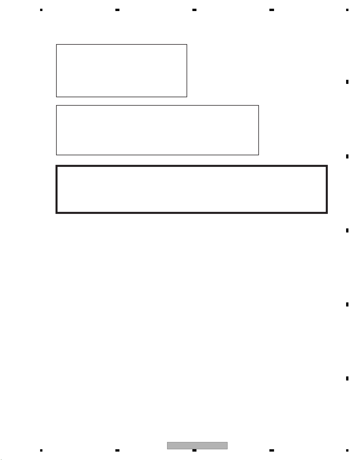
Laser diode characteristics
Wave length:
DVD:660 nm to 670 nm
CD:780 nm to 800 nm
Focus lens on Maximum output:
CD:6.26 mW(Emitting period :9 sec.)
DVD:1.27 mW (Emitting period : unlimited)
Additional Laser Caution
Transistors Q1103 and Q1104 in PCB drive the laser diodes for DVD and CD
respectively. When Q1103 or Q1104 is shorted between their terminals,
the laser diodes for DVD or CD will radiate beam. If the top cover is removed
with no disc loaded while such short-circuit is continued, the naked eyes may
be exposed to the laser beam.
CAUTION
Danger of explosion if battery is incorrectly replaced.
Replaced only with the same or equivalent type recommended by the manufacture.
Discord used batteries according to the manufacture's instructions.
AVH-3400DVD/XUEW5
3
Page 4

1234
1234
C
D
F
A
B
E
CONTENTS
SAFETY INFORMATION..................................................................................................................................... 2
1. SERVICE PRECAUTIONS............................................................................................................................... 5
1.1 SERVICE PRECAUTIONS ........................................................................................................................ 5
1.2 NOTES ON SOLDERING .......................................................................................................................... 6
2. SPECIFICATIONS............................................................................................................................................ 7
2.1 SPECIFICATIONS ..................................................................................................................................... 7
2.2 DISC/CONTENT FORMAT ...................................................................................................................... 14
3. BASIC ITEMS FOR SERVICE........................................................................................................................ 15
3.1 CHECK POINTS AFTER SERVICING..................................................................................................... 15
3.2 PCB LOCATIONS .................................................................................................................................... 16
3.3 JIGS LIST ................................................................................................................................................ 16
3.4 CLEANING............................................................................................................................................... 17
4. BLOCK DIAGRAM.......................................................................................................................................... 18
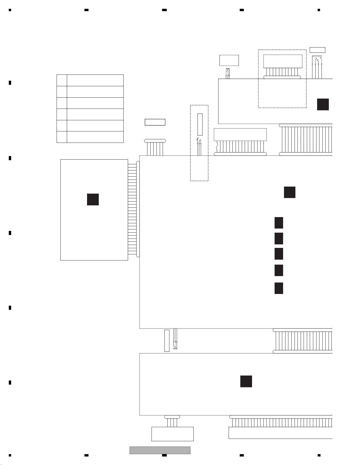
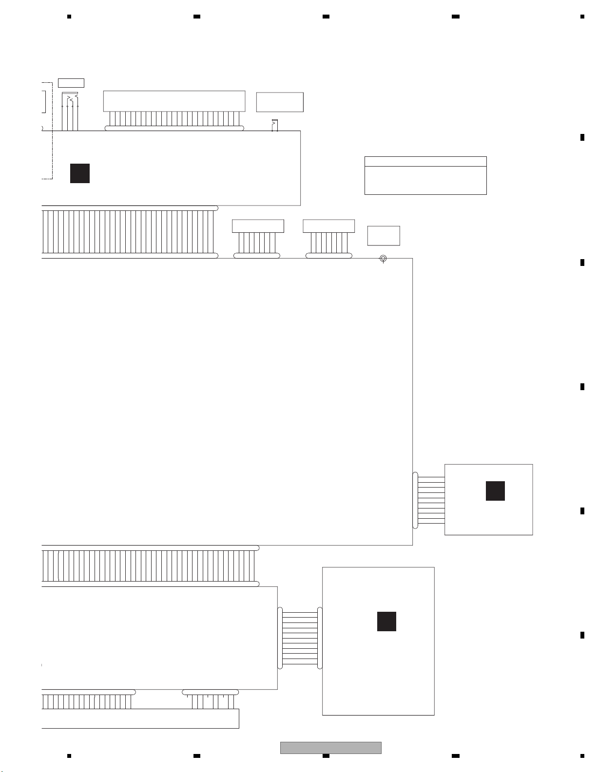
4.1 OVERALL CONNECTION DIAGRAM...................................................................................................... 18
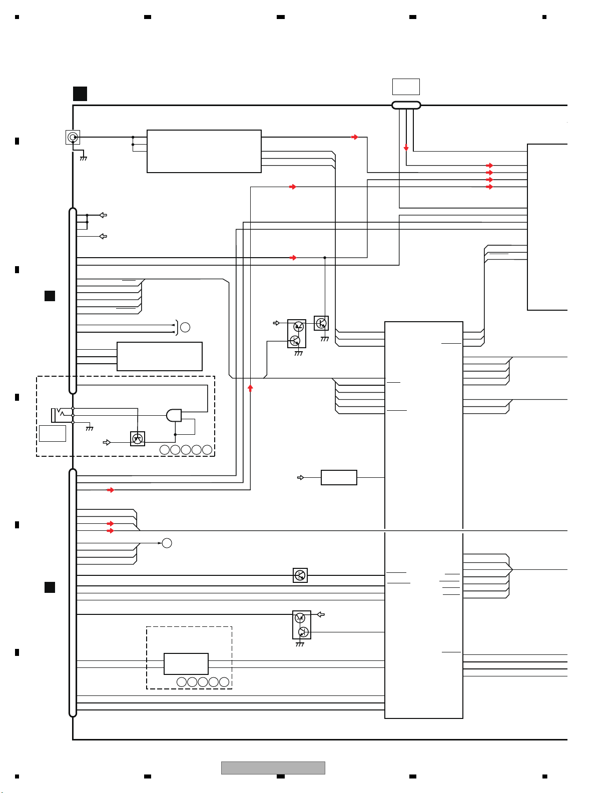
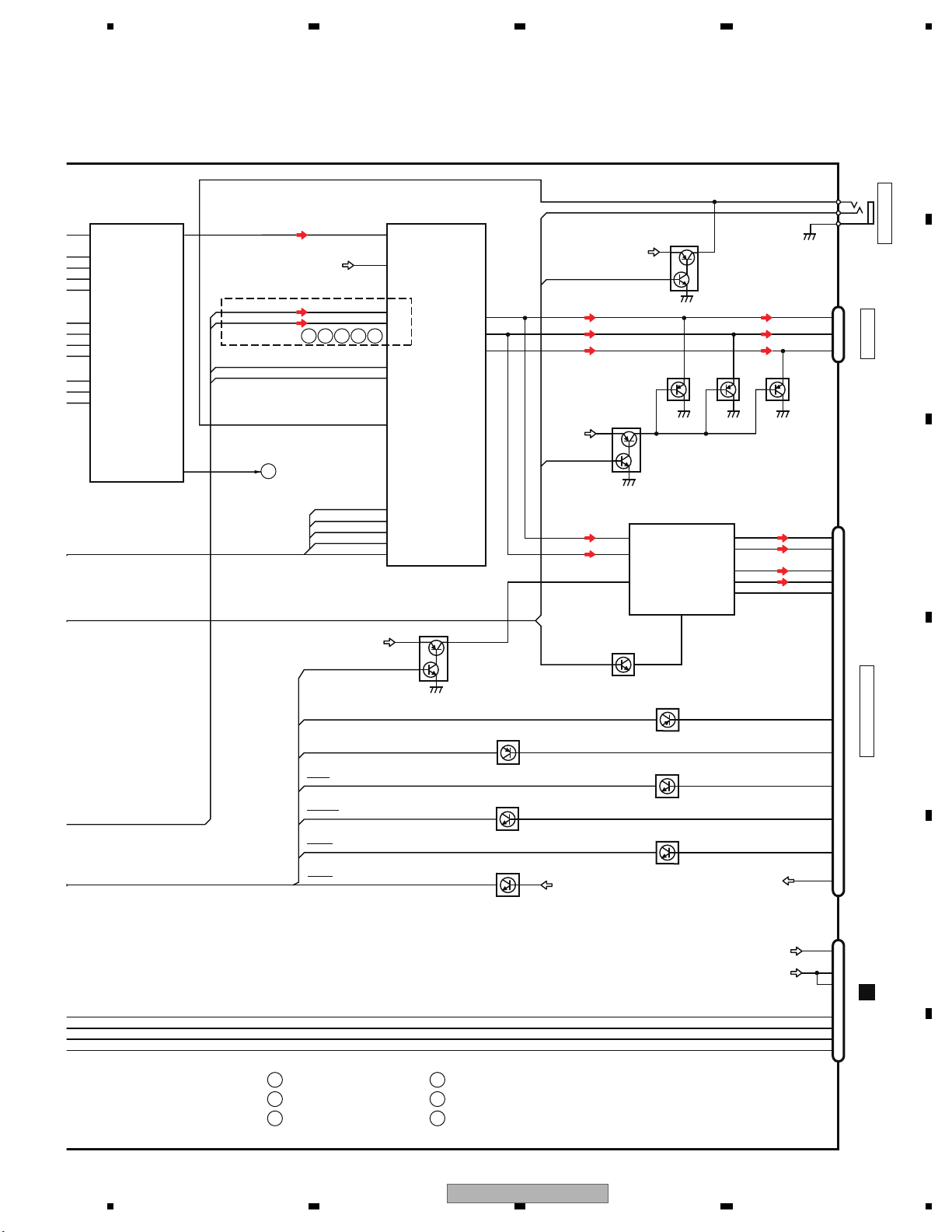
4.2 BLOCK DIAGRAM ................................................................................................................................... 20
5. DIAGNOSIS.................................................................................................................................................... 29
5.1 OPERATIONAL FLOWCHART................................................................................................................ 29
5.2 INSPECTION METHOD OF PICKUP UNIT............................................................................................. 30
5.3 DIAGNOSIS FLOWCHART ..................................................................................................................... 33
5.4 ERROR CODE LIST ................................................................................................................................ 53
5.5 CONNECTOR FUNCTION DESCRIPTION............................................................................................. 56
6. SERVICE MODE ............................................................................................................................................ 57
6.1 MONITOR TEST MODE.......................................................................................................................... 57
6.2 DVD TEST MODE ................................................................................................................................... 67
7. DISASSEMBLY .............................................................................................................................................. 72
8. EACH SETTING AND ADJUSTMENT ........................................................................................................... 78
8.1 DVD ADJUSTMENT ................................................................................................................................ 78
8.2 PCL OUTPUT CONFIRMATION .............................................................................................................. 83
9. EXPLODED VIEWS AND PARTS LIST.......................................................................................................... 84
9.1 PACKING ................................................................................................................................................. 84
9.2 EXTERIOR (1) ......................................................................................................................................... 88
9.3 EXTERIOR (2) ......................................................................................................................................... 90
9.4 EXTERIOR (3) ......................................................................................................................................... 92
9.5 DVD MECHANISM MODULE (1)............................................................................................................. 94
9.6 DVD MECHANISM MODULE (2)............................................................................................................. 96
10. SCHEMATIC DIAGRAM............................................................................................................................... 98
10.1 MOTHER PCB (ANALOG BLOCK)........................................................................................................ 98
10.2 MOTHER PCB (SYSTEM BLOCK) (GUIDE PAGE) ............................................................................ 100
10.3 MOTHER PCB (POWER SUPPLY BLOCK)........................................................................................ 106
10.4 MOTHER PCB (IN/OUT BLOCK) (GUIDE PAGE) ............................................................................... 108
10.5 MOTHER PCB (TUNER BLOCK).........................................................................................................114
10.6 IF PCB ..................................................................................................................................................116
10.7 DVD CORE UNIT (GUIDE PAGE) ........................................................................................................118
10.8 SERVICE UNIT(MONITOR) (GUIDE PAGE) ....................................................................................... 124
10.9 SERVICE UNIT (KEYBOARD)............................................................................................................. 130
10.10 PCB UNIT (SERVICE) ....................................................................................................................... 132
10.11 WAVEFORMS .................................................................................................................................... 134
11. PCB CONNECTION DIAGRAM.................................................................................................................. 136
11.1 MOTHER PCB ..................................................................................................................................... 136
11.2 IF PCB.................................................................................................................................................. 140
11.3 DVD CORE UNIT ................................................................................................................................. 142
11.4 SERVICE UNIT (MONITOR)................................................................................................................ 144
11.5 PCB UNIT (SERVICE) .........................................................................................................
11.6 SERVICE UNIT (KEYBOARD)............................................................................................................. 150
12. ELECTRICAL PARTS LIST ........................................................................................................................ 151
................ 148
4
AVH-3400DVD/XUEW5
Page 5
5 678
56
7
8
C
D
F
A
B
E
1. You should conform to the regulations governing the product (safety, radio and noise, and other regulations), and
should keep the safety during servicing by following the safety instructions described in this manual.
2. Be careful in handling ICs. Some ICs such as MOS type are so fragile that they can be damaged by electrostatic
induction.
3. Please be sure to conduct line process to original status if you make assembling after repair.
4. Please be careful of not to imply static charge onto integrated circuits, etc, when you conduct repair work.
Especially, please use soldering iron with its tip grounded.
Also, please use a pair of tweezers with static charge protection capability if there is the possibility of contacting to
device terminals, and avoid the use of metal-made tweezers.
5. Before disassembling the unit, be sure to turn off the power. Unplugging and plugging the connectors during power-on
mode may damage the ICs inside the unit.
6. To protect the pickup unit from electrostatic discharge during servicing, take an appropriate treatment (shorting-solder)
by referring to "the DISASSEMBLY".
7. Please keep the distance of more than 13 cm from focus lens for safety when you check pickup and make adjustment,
and do not look straight at Laser Beam for more than 10 seconds.
8. Please power adjustment when you replaced mechanical area of DVD Mecha Module or DVD core unit.
9. Graphically-illustrated areas become hot . Be careful not to burn yourself.
10. The acceptance surface of the remote controller on the keyboard PCB is not fixed with a cushion or other materials.
External force applied on the acceptance surface of the remote controller may distort the lead and change the mounting
angle of the acceptance surface, and accordingly, deteriorate the light sensitivity.
Do not apply external force on the acceptance surface of the remote controller.
If you accidentally apply external force, check whether the lead is bent or not.
If the lead is bent, repair it so that the angle between the lead and the acceptance surface becomes 90 degrees, or
exchange the acceptance surface for the remote controller (PNJ4833M).
11. When a home product is used in a vehicle (using DC/AC converter), GND on secondary side of some devices of home
products (PS etc.) becomes indefinite. If these devices are connected to AVH, GND becomes indefinite because ISO is
received and the video disordered.
If a defect is generated in a market, the land is prepared between GNDs for connecting GND of AVH sides and VGND of
input as a service.
With this product, a part of VGND pattern is thin. If it is used, insert 0.5A of fuse.
A used part and wiring numbers are shown below.
Wiring number: P531, P532
Used part: CEK1379 or CEK1278
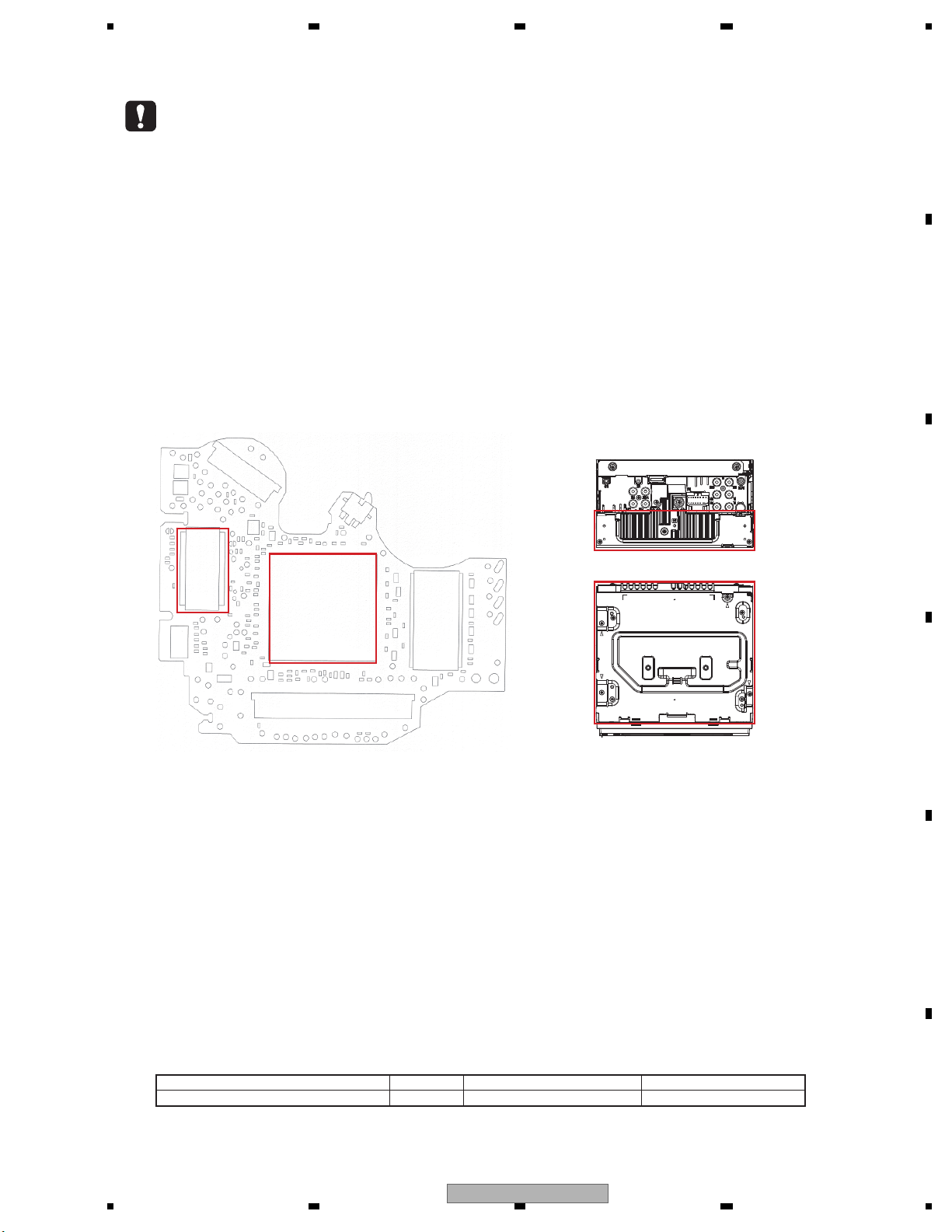
12. The part listed below is difficult to replace as a discrete component part.
When the part listed in the table is defective, replace whole Assy.
13. On this mechanism, Pickup and Spindle Motor can not be replaced at the service site, because a special facility is
required for the adjustment after replacing them.
So, if Pickup or Spindle Motor is defective, replace the Mechanism Unit.
Main IC
IC1501
Drive
IC
IC1251
SERVICE UNIT (MONITOR)
MOTHER PCB
IC5301 OZ527IRN
Heat pad
IC751 341S2162
QFN package
Heat Sink
Holder
Case
1. SERVICE PRECAUTIONS
1.1 SERVICE PRECAUTIONS
AVH-3400DVD/XUEW5
5
Page 6

1234
1234
C
D
F
A
B
E
1.2 NOTES ON SOLDERING
For environmental protection, lead-free solder is used on the printed circuit boards mounted in this unit.
Be sure to use lead-free solder and a soldering iron that can meet specifications for use with lead-free solders for repairs
accompanied by reworking of soldering.
Compared with conventional eutectic solders, lead-free solders have higher melting points, by approximately 40 C.
Therefore, for lead-free soldering, the tip temperature of a soldering iron must be set to around 373 C in general, although
the temperature depends on the heat capacity of the PC board on which reworking is required and the weight of the tip of
the soldering iron.
Compared with eutectic solders, lead-free solders have higher bond strengths but slower wetting times and higher melting
temperatures (hard to melt/easy to harden).
The following lead-free solders are available as service parts:
Parts numbers of lead-free solder:
GYP1006 1.0 in dia.
GYP1007 0.6 in dia.
GYP1008 0.3 in dia.
6
AVH-3400DVD/XUEW5
Page 7

5 678
56
7
8
C
D
F
A
B
E
General
Rated power source.............. 1 4.4 V DC
(allowable voltage range:
10.8 V to 15.1 V DC)
Grounding system.................. Negative type
Maximum current consumption
................................................... 10. 0 A
Dimensions (W × H × D):
DIN
Chassis.................... 178 mm × 1 00 mm ×
157 mm
Nose.......................... 188 mm × 118 mm ×
26 mm
D
Chassis.................... 178 mm × 1 00 mm ×
165 mm
Nose.......................... 171 mm × 97 mm × 1 8 mm
Weight ........................................ 2.0 kg
Display
Screen size/aspect ratio...... 6. 95 inch wide/16:9
(effective display area:
156.4 mm × 81.7 mm)
Pixels ........................................... 34 5 600 (1 440 × 240)
Display method ....................... TFT active matrix, driving
type
Color system............................ NTSC/PAL/PAL-M/PAL-N/
SECAM compatible
Durable temperature range (power off)
.................................................. –2 0 °C to +80 °C
Audio
Maximum power output ...... 50 W × 4
70 W × 1/2 Ω (for subwoofer)
Continuous power output ...22 W × 4 (50 Hz to
15 000 Hz, 5 %THD,
4 Ω load, both channels driven)
Load impedance ..................... 4 Ω (4 Ω to 8 Ω (2 Ω for 1 ch)
allowable)
Preout maximum output level
.................................................. 4. 0 V
Equalizer (8-Band Graphic Equalizer):
Frequency......................... 40 Hz /80 Hz/200Hz/400 Hz/
1 kHz/2.5 kHz/8 kHz/10 kHz
Gain .................................... ±12 dB
HPF:
Frequency......................... 50 Hz /63 Hz/80Hz/100 Hz/
125 Hz
Slope...................................–1 2 dB/oct
Subwoofer (mono):
Frequency......................... 50 Hz /63 Hz/80Hz/100 Hz/
125 Hz
Slope...................................–1 8 dB/oct
Gain ..................................... +6 dB t o –24 dB
Phase .................................Normal/Reverse
Bass boost:
Gain ..................................... +12 dB to 0 d B
DVD Player
System ........................................ D VD video, Video CD, CD,
WMA, MP3, AAC, DivX,
JPEG, MPEG system
Usable discs .............................DV D video, Video CD, CD,
CD-R/RW, DVD-R/RW/R DL
Region number ....................... 2
Frequency response.............. 5 H z to 44 0 00 Hz (with DVD,
at sampling frequency
96 kHz)
Signal-to-noise ratio.............. 96 d B (1 kHz) (IEC-A net-
work) (RCA level)
Output level:
Video.................................. 1.0 Vp-p/75 Ω (±0.2 V)
Number of channels ............. 2 (st ereo)
MP3 decoding format .......... M PEG -1 & 2 Au dio Layer 3
WMA decoding format ........ Ver. 7, 7. 1, 8, 9, 10 , 11, 12
(2 ch audio)
(Windows Media Player)
AAC decoding format........... MP EG-4 AAC (iTun es en-
coded only) (.m4a)
(Ver. 9.0.3 and earlier)
DivX decoding format........... Hom e Theater Ver. 3, 4, 5.2,
6 (.avi, .divx)
• EW5 Type
Backup current ................... 5 mA or less
2. SPECIFICATIONS
2.1 SPECIFICATIONS
AVH-3400DVD/XUEW5
7
Page 8

1234
1234
C
D
F
A
B
E
MPEG video decoding format
................................................... MPEG1, MPEG2, MPEG4
USB
USB standard specification
................................................... USB 1.1, US B 2.0 full speed
Maximum current supply ... 1.0 A
USB Class................................. MS C (Mass Storage Class)
File system................................ FAT16, FAT 32
MP3 decoding format .......... M PEG -1 & 2 Audio Layer 3
WMA decoding format ........ Ver. 7, 7. 1, 8, 9, 10 , 11, 12
(2 ch audio)
(Windows Media Player)
AAC decoding format........... MP EG-4 AAC (iTun es en-
coded only)
(Ver. 9.0.3 and earlier)
DivX decoding format........... Hom e Theater Ver. 3, 4, 5.2,
6 (.avi, .divx)
MPEG video decoding format
.................................................. MPEG1, MPEG2, MPEG4
FM tuner
Frequency range.................... 87. 5 MHz to 108.0 MHz
Usable sensitivity................... 9 dBf (0.8 µV/75 Ω, mono,
S/N: 30 dB)
Signal-to-noise ratio.............. 72 d B (IEC-A network)
MW tuner
Frequency range.................... 531 kHz to 1 602 kHz (9 kHz)
Usable sensitivity................... 2 5 µV (S/N: 20dB)
Signal-to-noise ratio............. 62 d B (IEC-A network)
LW tuner
Frequency range..................... 153 kHz to 281 kHz
Usable sensitivity.................... 28 µV (S/N: 20 dB)
Signal-to-noise ratio.............. 62 d B (IEC-A network)
Note
Specifications and the design are subject to modifications without notice.
8
AVH-3400DVD/XUEW5
Page 9

5 678
56
7
8
C
D
F
A
B
E
General
Rated power source.............. 1 4.4 V DC
(allowable voltage range:
10.8 V to 15.1 V DC)
Grounding system................. Negative type
Maximum current consumption
................................................... 10. 0 A
Dimensions (W × H × D):
DIN
Chassis.................... 178 mm × 1 00 mm ×
157 mm
Nose.......................... 188 mm × 118 mm ×
26 mm
D
Chassis.................... 178 mm × 1 00 mm ×
165 mm
Nose.......................... 171 mm × 97 mm × 1 8 mm
Weight ........................................ 2.0 kg
Display
Screen size/aspect ratio...... 6. 95 inch wide/16:9
(effective display area:
156.4 mm × 81.7 mm)
Pixels .......................................... 3 45 600 (1 440 × 240)
Display method ...................... TF T active matrix, driving
type
Color system............................ NTSC/PAL/PAL-M/PAL-N/
SECAM compatible
Durable temperature range (power off)
.................................................. –2 0 °C to +80 °C
Audio
Maximum power output ....... 50 W × 4
70 W × 1/2 Ω (for subwoofer)
Continuous power output ...22 W × 4 (50 Hz to
15 000 Hz, 5 %THD,
4 Ω load, both channels driven)
Load impedance .................... 4 Ω (4 Ω to 8 Ω (2 Ω for 1 ch)
allowable)
Preout maximum output level
.................................................. 4. 0 V
Equalizer (8-Band Graphic Equalizer):
Frequency........................ 40 H z/8 0 Hz/200 Hz/400 Hz/
1 kHz/2.5 kHz/8 kHz/10 kHz
Gain .................................... ±12 dB
HPF:
Frequency........................ 50 H z/6 3 Hz/80 Hz/100 Hz/
125 Hz
Slope.................................. –12 dB/oct
Subwoofer (mono):
Frequency........................ 50 H z/6 3 Hz/80 Hz/100 Hz/
125 Hz
Slope.................................. –18 dB/oct
Gain .................................... + 6 dB to – 24 dB
Phase ................................ Normal/Reverse
Bass boost:
Gain .................................... +12 dB to 0 dB
DVD Player
System ........................................ D VD video, Video CD, CD,
WMA, MP3, AAC, DivX,
JPEG, MPEG system
Usable discs ............................ DVD video, Video CD, CD,
CD-R/RW, DVD-R/RW/R DL
Region number ...................... 5
Frequency response............. 5 Hz to 44 0 00 Hz (with DVD,
at sampling frequency
96 kHz)
Signal-to-noise ratio.............. 96 d B (1 k Hz) (IEC-A net-
work) (RCA level)
Output level:
Video.................................. 1.0 Vp-p/75 Ω (±0.2 V)
Number of channels ............. 2 (st ereo)
MP3 decoding format .......... M PEG -1 & 2 Audio Layer 3
WMA decoding format ........ Ver. 7, 7. 1, 8, 9, 10 , 11, 12
(2 ch audio)
(Windows Media Player)
AAC decoding format........... MP EG-4 AAC (iTun es en-
coded only) (.m4a)
(Ver. 9.0.3 and earlier)
DivX decoding format........... Hom e Theater Ver. 3, 4, 5.2,
6 (.avi, .divx)
• UW5 Type
Backup current ................... 5 mA or less
AVH-3400DVD/XUEW5
9
Page 10

1234
1234
C
D
F
A
B
E
MPEG video decoding format
.................................................. MPEG1, MPEG2, MPEG4
USB
USB standard specification
.................................................. US B 1.1, US B 2.0 ful l speed
Maximum current supply .... 1.0 A
USB Class................................. MS C (Mass Storage Class)
File system................................ FAT16, FAT32
MP3 decoding format .......... MPEG-1 & 2 Audio Layer 3
WMA decoding format ........ Ver. 7, 7. 1, 8, 9, 10 , 11, 12
(2 ch audio)
(Windows Media Player)
AAC decoding format........... MPEG-4 AAC (iTunes en-
coded only)
(Ver. 9.0.3 and earlier)
DivX decoding format........... Hom e Theater Ver. 3, 4, 5.2,
6 (.avi, .divx)
MPEG video decoding format
.................................................. MPEG1, MPEG2, MPEG4
FM tuner
Frequency range.................... 87. 5 MHz to 108.0 MHz
Usable sensitivity................... 9 dBf (0.8 µV/75 Ω, mono,
S/N: 30 dB)
Signal-to-noise ratio.............. 72 d B (IEC-A network)
MW tuner
Frequency range.................... 531 kHz to 1 602 kHz (9 kHz)
Usable sensitivity................... 2 5 µV (S/N: 20dB)
Signal-to-noise ratio.............. 62 d B (IEC-A network)
LW tuner
Frequency range..................... 153 kHz to 281 kHz
Usable sensitivity................... 2 8 µV (S/N: 20 dB)
Signal-to-noise ratio.............. 62 d B (IEC-A network)
Note
Specifications and the design are subject to modifications without notice.
10
AVH-3400DVD/XUEW5
Page 11

5 678
56
7
8
C
D
F
A
B
E
General
Power source............................ 14. 4 V DC (12.0 V to 14.4 V
allowable)
Grounding system.................. Negative type
Maximum current consumption
................................................... 10. 0 A
Dimensions (W × H × D):
DIN
(For Middle East Asian and South African models)
Chassis.................... 178 mm × 1 00 mm ×
157 mm
Nose.......................... 188 mm × 118 mm ×
26 mm
D
Chassis.................... 178 mm × 1 00 mm ×
165 mm
Nose.......................... 171 mm × 97 mm × 1 8 mm
Weight ........................................ 2.0 kg
Display
Screen size/aspect ratio...... 6. 95 inch wide/16:9
(effective display area:
156.4 mm × 81.7 mm)
Pixels .......................................... 3 45 600 (1 440 × 240)
Display method ...................... TF T active matrix, driving
type
Color system............................ NTSC/PAL/PAL-M/PAL-N/
SECAM compatible
Durable temperature range (power off)
.................................................. –2 0 °C to +80 °C
Audio
Maximum power output ...... 50 W × 4
70 W × 1/2 Ω(for subwoo-
fer)
Continuous power output ...22 W × 4 (50 Hz to
15 000 Hz, 5 %THD,
4 Ω load, both channels driven)
Load impedance .................... 4 Ω (4 Ω to 8 Ω (2 Ω for 1 ch)
allowable)
Preout maximum output level
.................................................. 4. 0 V
Equalizer (8-Band Graphic Equalizer):
Frequency......................... 40 Hz /80 Hz/200Hz/400 Hz/
1 kHz/2.5 kHz/8 kHz/10 kHz
Gain .................................... ±12 dB
HPF:
Frequency........................ 50 H z/6 3 Hz/80 Hz/100 Hz/
125 Hz
Slope.................................. –12 dB/oct
Subwoofer (mono):
Frequency......................... 50 Hz /63 Hz/80Hz/100 Hz/
125 Hz
Slope.................................. –18 dB/oct
Gain .................................... + 6 dB to – 24 dB
Phase .................................Normal/Reverse
Bass boost:
Gain .................................... +12 dB to 0 dB
DVD Player
System ........................................ D VD video, Video CD, CD,
WMA, MP3, AAC, DivX,
JPEG, MPEG system
Usable discs ............................ DVD video, Video CD, CD,
CD-R/RW, DVD-R/RW/R DL
Region number ....................... 2
(For Middle East Asian and South African models)
Region number ....................... 3
(For Southeast Asian models)
Region number ....................... 4
(For South American and Oceanian models)
Frequency response.............. 5 H z to 44 0 00 Hz (with DVD,
at sampling frequency
96 kHz)
Signal-to-noise ratio.............. 96 d B (1 k Hz) (IEC-A net-
work) (RCA level)
Output level:
Video.................................. 1.0 Vp-p/75 Ω (±0.2 V)
Number of channels ............. 2 (st ereo)
MP3 decoding format .......... M PEG -1 & 2 Audio Layer 3
WMA decoding format .........Ve r. 7, 7.1, 8, 9, 10, 11, 12
(2 ch audio)
(Windows Media Player)
• RC, RD and RI Types
Backup current ................... 5 mA or less
AVH-3400DVD/XUEW5
11
Page 12

1234
1234
C
D
F
A
B
E
AAC decoding format........... MPEG-4 AAC (iTunes en-
coded only) (.m4a)
(Ver. 9.0.3 and earlier)
DivX decoding format........... Hom e Theater Ver. 3, 4, 5.2,
6 (.avi, .divx)
MPEG video decoding format
.................................................. MPEG1, MPEG2, MPEG4
USB
USB standard specification
................................................... USB 1.1, US B 2.0 full speed
Maximum current supply ....1.0 A
USB Class................................. MS C (Mass Storage Class)
File system................................ FAT16, FAT32
MP3 decoding format ......... MPEG-1 & 2 Audio Layer 3
WMA decoding format ....... Ver. 7, 7. 1, 8, 9, 10, 11, 12
(2 ch audio)
(Windows Media Player)
AAC decoding format.......... MPEG-4 AAC (iTunes en-
coded only)
(Ver. 9.0.3 and earlier)
DivX decoding format.......... Home Theater Ver. 3, 4, 5.2,
6 (.avi, .divx)
MPEG video decoding format
.................................................. MPEG1, MPEG2, MPEG4
FM tuner
Frequency range.................... 87. 5 MHz to 108.0 MHz
Usable sensitivity................... 9 dBf (0. 8 µV/75 Ω, mono,
S/N: 30 dB)
Signal-to-noise ratio.............. 72 d B (IEC-A network)
AM tuner
Frequency range.................... 530 kHz to 1 640 kHz
(10 kHz)
531 kHz to 1 602kHz (9 kHz)
Usable sensitivity................... 2 5 µV (S/N: 20dB)
Signal-to-noise ratio............. 6 2 dB (IEC-A network)
Note
Specifications and the design are subject to modifications without notice.
12
AVH-3400DVD/XUEW5
Page 13

5 678
56
7
8
C
D
F
A
B
E
General
Power source............................ 14. 4 V DC (12.0 V to 14.4 V
allowable)
Grounding system.................. Negative type
Maximum current consumption
................................................... 10. 0 A
Dimensions (W × H × D):
D
Chassis.................... 178 mm × 1 00 mm ×
165 mm
Nose.......................... 171 mm × 97 mm × 1 8 mm
Weight ....................................... 2 .0 kg
Display
Screen size/aspect ratio...... 6. 95 inch wide/16:9
(effective display area:
156.4 mm × 81.7 mm)
Pixels .......................................... 3 45 600 (1 440 × 240)
Display method ...................... TF T active matrix, driving
type
Color system............................ NTSC/PAL/PAL-M/PAL-N/
SECAM compatible
Durable temperature range (power off)
.................................................. –2 0 °C to +80 °C
Audio
Maximum power output ...... 50 W × 4
70 W × 1/2 Ω (for subwoo-
fer)
Continuous power output .. 22 W × 4 (50 Hz to
15 000 Hz, 5 %THD,
4 Ω load, both channels dri-
ven)
Load impedance .................... 4 Ω (4 Ω to 8 Ω (2 Ω for 1 ch)
allowable)
Preout maximum output level
.................................................. 4. 0 V
Equalizer (8-Band Graphic Equalizer):
Frequency........................ 40 Hz/80 Hz/200 Hz/400 Hz/
1 kHz/2.5 kHz/8 kHz/10 kHz
Gain .................................... ±12 dB
HPF:
Frequency........................ 50 Hz/63 Hz/80 Hz/100 Hz/
125 Hz
Slope.................................. –12 dB/oct
Subwoofer (mono):
Frequency........................ 50 Hz/63 Hz/80 Hz/100 Hz/
125 Hz
Slope.................................. –18 dB/oct
Gain .................................... +6 dB to – 24 dB
Phase ................................ Normal/Reverse
Bass boost:
Gain .................................... +12 dB to 0 dB
DVD Player
System ........................................ D VD video, Video CD, CD,
WMA, MP3, AAC, DivX,
JPEG, MPEG system
Usable discs ............................ DVD video, Video CD, CD,
CD-R/RW, DVD-R/RW/R DL
Region number ....................... 5
Frequency response.............. 5 H z to 44 0 00 Hz (with DVD,
at sampling frequency
96 kHz)
Signal-to-noise ratio.............. 96 d B (1 k Hz) (IEC-A net-
work) (RCA level)
Output level:
Video.................................. 1.0 Vp-p/75 Ω (±0.2 V)
Number of channels ............ 2 (s tereo)
MP3 decoding format .......... M PEG -1 & 2 Audio Layer 3
WMA decoding format ........ Ver. 7, 7. 1, 8, 9, 10 , 11, 12
(2 ch audio)
(Windows Media Player)
AAC decoding format........... MP EG-4 AAC (iTun es en-
coded only) (.m4a)
(Ver. 9.0.3 and earlier)
DivX decoding format........... Hom e Theater Ver. 3, 4, 5.2,
6 (.avi, .divx)
MPEG video decoding format
.................................................. MPEG1, MPEG2, MPEG4
USB
USB standard specification
.................................................. US B 1.1, US B 2.0 full speed
Maximum current supply ....1.0 A
USB Class................................. MS C (Mass Storage Class)
File system................................ FAT16, FAT32
MP3 decoding format .......... M PEG -1 & 2 Audio Layer 3
WMA decoding format ........ Ver. 7, 7. 1, 8, 9, 10 , 11, 12
(2 ch audio)
(Windows Media Player)
• ID Type
Backup current ................... 5 mA or less
AVH-3400DVD/XUEW5
13
Page 14
1234
1234
C
D
F
A
B
E
AAC decoding format........... MP EG-4 AAC (iTun es en-
coded only)
(Ver. 9.0.3 and earlier)
DivX decoding format........... Hom e Theater Ver. 3, 4, 5.2,
6 (.avi, .divx)
MPEG video decoding format
.................................................. MPEG1, MPEG2, MPEG4
FM tuner
Frequency range.................... 87. 5 MHz to 108.0 MHz
Usable sensitivity................... 9 dBf (0.8 µV/75Ω, mono,
S/N: 30 dB)
Signal-to-noise ratio............. 7 2 dB (IEC-A network)
AM tuner
Frequency range.................... 530 kHz to 1 640 kHz
(10 kHz)
531 kHz to 1 602kHz (9 kHz)
Usable sensitivity................... 2 5 µV (S/N: 20dB)
Signal-to-noise ratio............. 6 2 dB (IEC-A network)
Note
Specifications and the design are subject to modifications without notice.
2.2 DISC/CONTENT FORMAT
14
AVH-3400DVD/XUEW5
Page 15
5 678
56
7
8
C
D
F
A
B
E
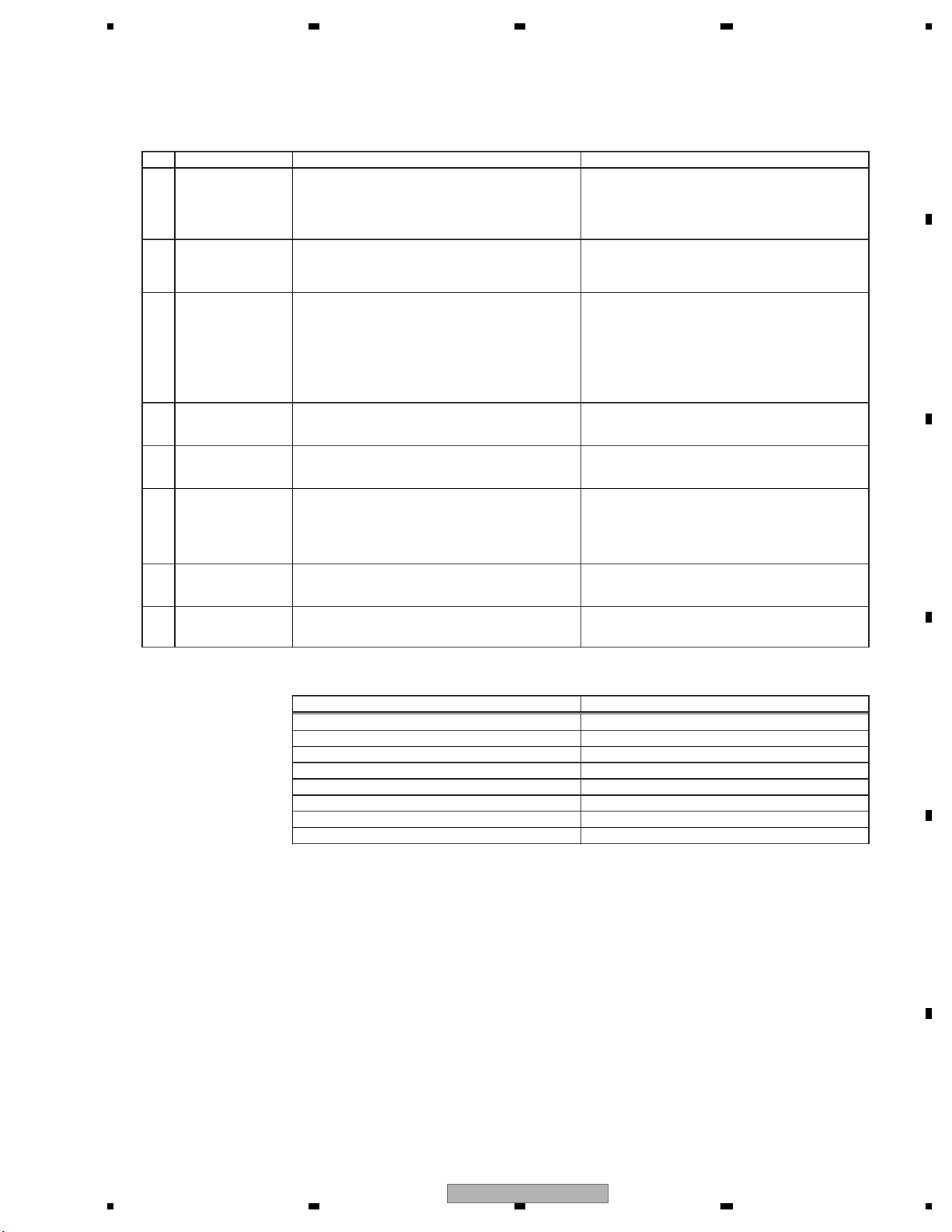
To keep the product quality after servicing, please confirm following check points.
No. Procedures Item to be confirmed
1 Confirm whether the customer complain has
been solved.
If the customer complain occurs with the
specific media, use it for the operation check.
The customer complain must not be
reappeared.
Display, video, audio and operations must be
normal.
3 DVD Measure playback error rates at the
innermost and outermost tracks by using the
test mode with the following disc.
DVD test disc (TDV-582)
Deterioration of mecha-drive can be
checked.
The error rate must be less than the
threshold value.
(Refer to the chapter of DIAGNOSIS for the
threshold value.)
4 DVD Play back a DVD.
(Menu operation; Title/chapter search)
Display, video, audio and operations must be
normal.
5 CD Play back a CD.
(Track search)
Display, audio and operations must be
normal.
6 FM/AM tuner Check FM/AM tuner action.
(Seek, Preset)
Switch band to check both FM and AM.
Display, audio and operations must be
normal. * If the reception sensitivity is poorer
than normal, the gasket on the FM/AM tuner
unit may be damaged or lost.
7 Check whether no disc is inside the product. The media used for the operating check must
be ejected.
8 Appearance check No scratches or dirt on its appearance after
receiving it for service.
For check items concerning image and voice, please refer to the followings:
Check items concerning image Check items concerning voice
Block-noise Distortion
Crosscut noise Noise
Dot noise Low volume
Distorted image (Image skip) High volume
Low brightness Changes in level
Too bright Pause of sound
Color fading
Partial discoloration
2 Flap-mecha Check the operation of the flap mechanism. The flap mechanism operation must be
smooth without making the noise and
scratches.
3. BASIC ITEMS FOR SERVICE
3.1 CHECK POINTS AFTER SERVICING
AVH-3400DVD/XUEW5
15
Page 16
1234
1234
C
D
F
A
B
E
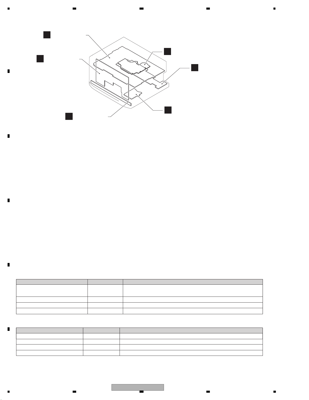
3.2 PCB LOCATIONS
E
Service Unit
(Keyboard)
D
Service Unit
(Monitor)
A
Mother PCB
C
DVD Core Unit
F
PCB Unit (Service)
B
IF PCB
A:AVH-3400DVD/XUEW5
B:AVH-P3400DVD/XUUW5
C:AVH-P3450DVD/XURC
D:AVH-P3450DVD/XURD
E:AVH-P3450DVD/XURI
F:AVH-P3490DVD/XUID
Service Unit(Mother I/F)
Consists of
Mother PCB
IF PCB
Unit Number : CXX4164(A)
Unit Number : CXX4165(B)
Unit Number : CXX4166(C)
Unit Number : CXX4167(D)
Unit Number : CXX4168(E)
Unit Number : CXX4169(F)
Unit Name : Service Unit(Mother I/F)
Unit Number : YWX5032
Unit Name : DVD Core Unit
Unit Number : CXX4179(A)(B)(D)(E)(F)
Unit Number : CXX4552(C)
Unit Name : Service Unit(Monitor)
Unit Number : CXX4182
Unit Name : Service Unit(Keyboard)
Unit Number : EXX2001
Unit Name : PCB Unit(Service)
- Grease List
- Jigs List
Name
Grease
Grease
Grease
Grease
Jig No.
GEM1024
GEM1038
GEM1045
GEM1043
Remarks
DVD Mechanism Module, Drive Unit
DVD Mechanism Module
DVD Mechanism Module
Drive Unit
Disc TDV-582 Skew adjustment, Check points after servicing,
Inspection method of Pickup Unit
Disc TCD-782 Inspection method of Pickup Unit
30P FFC GGD1222 DVD CORE UNIT <–> MOTHER PCB
10P FFC GGD1188 PCB UNIT (SERVICE) <–> MOTHER PCB
Name Jig No.
Remarks
3.3 JIGS LIST
16
AVH-3400DVD/XUEW5
Page 17
5 678
56
7
8
C
D
F
A
B
E
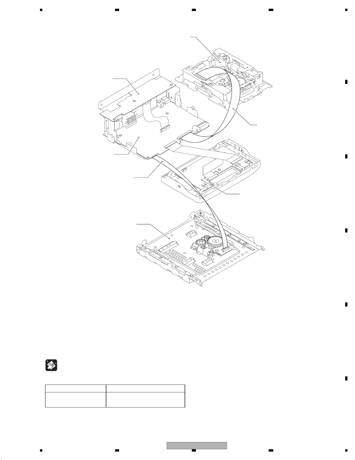
Before shipping out the product, be sure to clean the following portions by using the prescribed cleaning tools:
Portions to be cleaned Cleaning tools
DVD pickup lenses Cleaning liquid : GEM1004
Cleaning paper : GED-008
DVD Mechanism Module
IF PCB
Mother PCB
GGD1188
Drive Unit
GGD1222
Service Unit (Monitor)
3.4 CLEANING
AVH-3400DVD/XUEW5
17
Page 18
1234
1234
C
D
F
A
B
E
4. BLOCK DIAGRAM
Note: When ordering service parts, be sure to refer to " EXPLODED VIEWS AND PARTS LIST" or
"ELECTRICAL PARTS LIST".
GNDD
WIRED
WIREDAD
OPTSENS
OPTOUT
GND
VIDEO
AUXR
AUXL
GND
GNDD
1
BEEP
2
WIRED
3
WIREDAD
4
GNDD
5
GNDD
6
BUS+7BUS-8ASENBO9NAVI_TO_SYS
10
SYS_TO_NAVI
11
GUIDEON12TVON13GNDD14CSYNC15GNDSIG16ANB
17
1
TENPSENS
2
DIMMER
3
MBLPW
4
BLSYNC
5
BLERR6PWRBL7PWRBL8PWRBL
9
NC
10
GNDBL11GNDBL12GNDBL
13NC14
GNDV
15
MONVBS
16
GNDV
17
GNDSIG
18
ANAB
19
CSYNC
323334
353637
38394041424344454647484950
24
2526272829
30
313233
34
35
3637383940
JA2505
CKS5271-A
1
BUS+
2
BUSG
3
BUSLG
4
MAINTEST
5
BUS-
6
BUSRG
7
BUSL+
8
ASENBO
9
BUSR+
10
BUSR-11BUSL-
CKS6025-A
CN701
1
VD8
2
VD8
3
VD8
4
PGND
5
PGND
6
PGND
7
VD5
8
AMUTE
9
XRESET
10
IRQPWR
11
HSTCMD
12
SLVSTS
13
STANBY
14
AGND
15
ANA_R_OUT
16
AND
17
ANA_L_OUT
18
AGND
19
MOVBS
20
VIDEO_GND
21
WAKEUP
22
D-
23
D+
24
DGND
25
IECOUT
26
DGND
27
SCL
28
SDA
29
CPRST
30
CPRDY
JA121
CKM1376-A
1
FR-2RR-
3
FR+4RR+5FL-
6
RL-7FL+8RL+
9
P.B.
10
MUTE
11
SYSREM
12
ILM
13
BGSENS
14
ACC15GND16BUP
CKS5708-A
CN5701
VCC
8
NC
9
TEST
10
TEST11TEST
12
VSYNC13HSYNC
14
GND
15
SHUT
16
GND
17R518R419R320R221R122R023
GND
24G525G426G327G228G129G030
GND
31B532B433B334B235
B136B0
37
GND
38
DCLK
39
GND
40
CN5101
CKS6327-A
1
PLYV2PLXV3ADVX4ADVY
JA2504
CKS4124-A
2
3
1
12
JA551
CKN1042-A
231
JA2503
AKN1073-A
123
4
CKN1091-A
JA571
USB5V
USB_D-
USB_D+
USBGND
Shield1
Shield2
1
2
3
4
RT1
RT2
LCD
IP BUS
TOUCH PANEL
WIRED
REMOTE
POWER SUPPLY
YEK5001-A
S/PDIF OUT
AUX IN
USB IF
CN1952
AEQMICIN
MICSENSR
GND
JA431
CKS4124-A
2
3
1
AEQMIC IN
A
B
C
D
E
F
AVH-3400DVD/XUEW5
AVH-P3400DVD/XUUW5
AVH-P3450DVD/XURC
AVH-P3450DVD/XURD
AVH-P3450DVD/XURI
AVH-P3490DVD/XUID
B
I
D
SERVICE UNIT(MONITOR
A
MOTHER P
C
DVD MECHANISM
MODULE
(LS2)
TUNER BLO
5/5
A
IN/OUT BLO
4/5
A
POWER SUP
3/5
A
SYSTEM BLO
2/5
A
ANALOG BL
1/5
A
except A
except A
4.1 OVERALL CONNECTION DIAGRAM
18
AVH-3400DVD/XUEW5
Page 19
5 678
56
7
8
C
D
F
A
B
E
SWLOUT
RLOUT
FROUT
GNDA
FLOUT
SWROUT
GNDA
RROUT
GNDKEY
REM
NC
KDT0
VCC34
LEDB1
LEDG1
LEDR1
KDT1
ILMB
GNDKEY
VIDEO
AUXR
AUXL
GND
CKS6051-A
CN451
7
BUS-8ASENBO9NAVI_TO_SYS
10
SYS_TO_NAVI
11
GUIDEON12TVON13GNDD14CSYNC15GNDSIG16ANB17GNDSIG18ANG19GNDSIG20ANR21GNDSIG22NC23BUSR+24BUSR-25GNDD26BUSL-27BUSL+28ONSEI-29ONSEI+30AUXAGND31AUXL32AUXAGND33AUXR34AUXVGND
35
AUXV
36
BCAMGND
37
BCAMIN
38
BTMICN
39
BTMICP
40
CN2502
CKS4497-A
1
ANR2ANG
3
ANB
4
CSYNC
5
GNDSIG
6
DVDVBS
7
GNDDVD
8YS9
ASENBO
10
CCAUL
11
CCAUR12GNDAU
14
ONSEI-
15
REAUR16REAUL
17
GNDRAU
18
CCREM
19
DSEN20TVON
21
GUIDEON
22
MONON
23
VSW5
24
SYS_TO_NAVI
25
NAVI_TO_SYS
26
GNDD
13
ONSEI+
JA1401
1
1
2
2
CKB1102-A
JA531
VCR_RG
1
VCR_RIN
2
VOUT_G
3
VOUT
4
VCR_LG
5
VCR_LIN
6
VCR_VG
7
VCR_VIN
8
CKS6297-A
CN301
9
NC
10
GNDBL11GNDBL12GNDBL
13NC14
GNDV
15
MONVBS
16
GNDV
17
GNDSIG
18
ANAB
19
CSYNC
20
ANAR21ANAG
22
GNDSIG
23
GRST
24
GtoS
25
StoG
26NC27
ILMB
28NC29
GNDILM
30
439KDT0
31
439KDT1
32
439REM
33
NC
34
GNDD
35
GNDD
36
439LEDB
37
439LEDG
38
439LEDR
39
PLYV
40
PLXV
41
ADVX
42
ADVY
43
PWGR
44
GNDD
45
GNDD
46
GNDD
47NC48
PWRVI
49
PWRVI
50
PWRVI
CKS6297-A
CN5001
123456789
101112131415161718192021222324
252627282930313233
34
353637
3839404142
CKS6051-A
CN2501
1
2
3456789
10
111213
14
15
16
17
181920
212223
24
2526272829
30
313233
34
JA2502
2
BCAMIN
1
BCAMGND
XKB7001-B
JA501
1
2
34567
8
GND
1
GND2GND
3NC4
VCC
5
VCC6VCC7VCC
8
NC
9
TEST
10
TEST11TEST
12
VSYNC13HSYNC
14
GND
15
SHUT
16
GND
17R518
CKS6233-A
CN5301
1
NC2LED33LED24LED15NC6BLPWR
7
BLPWR8NC9TEMPSEN10GNDBL
CKS6291-A
CN3001
1
2
3
4
5
6
7
8
9
10
11
CKS6286-A
CN5501
1
2
3
4
5
6
7
8
9
10
11
JA2503
AKN1073-A
123
4
CKS6095-A
CN431
1
2
3
4
5
6
7
8
9
10
LCD
NAVI INTERFACE
REAR CAMERA
INPUT
FM/AM
PREOUTRCA V IN OUT
ANT
BACKLIGHT
YKS5041-A
CKB1065-A
AUX IN
MOTV
MOTV
GNDD
GNDD
MOT0
MOT1
POS
VDD33
GNDD
H/OSW
CN101
B
IF PCB
E
SERVICE UNIT
(KEYBOARD)
F
PCB UNIT
(SERVICE)
SERVICE UNIT(MOTHER I/F)
Consists of
MOTHER PCB
IF PCB
AVH-3400DVD/XUEW5
19
Page 20
1234
1234
C
D
F
A
B
E
4.2 BLOCK DIAGRAM
ISENS
84
53
SYSMUTE
44
AMPPW
16
RESET
ASENS
80
BSENS
82
TELMUTEIN
85
PBSENS
86
BGSENS
58
Q603
137
MOT0
138
MOT1
176
POS
133
H&OSW
JA1401
TDA7706
IC1401
FM/AM TUNER IC
31
33
34
TUNCLK
TUNDATA
TUNRST
I2CSCL
I2CSDA
RSTN
57
TUN_L
DACOUTL
16
5
FMMIXINT
PINDIN
18
LNAIN
62
TUNDATA
TUNRST
61
TUNCKL
TUNCLK
60
19
8
9
10
11
12
13
22
25
MOVBS
AMUTE
XRESET
IRQPWR
IECOUT
HSTCMD
SLVSTS
STANBY
ANA_L_OUT
17
CN701
27
28
29
SCL
SDA
CPRST
23
4
2
TC7SET08FUS1
IC551
12
13
4
I2C_SCL
I2C_SDA
nRESET
341S2162
IC751
iPod CP IC
1
5
Q551
DD5
1
3
2
JA551
XRST
IRQPW
SYSTOLS
LSTOSYS
STANBY
158
51
LSTOSYS
52
20
STANBY
AMUTE
IRQPW
SYSTOLS
157
XRST
159
PE5796A8
IC602(1/2)
SYSTEM uCOM
27
5
VIN4
30
3
VIN2
LIN3
LIN6
LIN5
33
LIN4
36
45
VOUT2
46
17
SCL
SDA
RSTN
13
AK4223V
IC251
AV SELECT
VCR_LIN
VCR_VIN
VOUT
JA531
684
9
7
VIN3
VIN5
VCR_V
LS_V
TUN_L
LS_L
AUX_L
VCR_L
AUX_V
BCAMIN
36
38
13
12
10
29
32
AUXL
AUXV
BCAMIN
GNDD
OPTOUT
OPTSENS
TVON
GUIDEON
NAVI_TO_SYS
ONSEI-
ASENBO
9
BUS-
8
BUS+
7
BEEP
WIRED
30
ONSEI+
2
3
4
11
SYS_TO_NAVI
Q451
BUP_1
27
BUSL-
28
BUSL+
CN451
SPDIF
AVSCK
AVSDATA
AVSRST
WIREDAD
55
54
56
164
57
63
67
68
AVSCK
AVSDATA
AVSRST
EVSDA
EVSCK
SACLK
162
MICSEN
SAIN
EVSEL
35
31
30
28
29
GUIDEON
TXNAVI
RXNAVI
161
WIREDAD
160
WIRED
34
BEEP
ASENBO
37
RXIP
36
TXIP
RGBARI
A
S/PDIF
OUT
RCA V
IN/OUT
RCA_V
1
2
VDD33
RESET
S-80829CNMC-B80
IC601
OUTVDD
5
6
2
1
BUSBUS+
ROUT
DIN1
HA12241FP
IC531
IP-BUS DRIVER
105
AEQAUXSW
TO 2/2
19
ANG
21
ANR
15
CSYNC
17
ANB
TO 2/2
CN1952
C
CN2501
B
1
1
2
3
VD8
7VD5
2,3
FM/AM
TELMUTE
ANTENNA
MOTHER PCB (1/2)
AMUTE
Q702
Q701
SYS+B
BCDEF
BCDEF
G
I
DD+
DD+
20
AVH-3400DVD/XUEW5
Page 21
5 678
56
7
8
C
D
F
A
B
E
MIC SENS
RL
FL
SWL
ISENS
BUP_1
BUP_1
SYS+B
FL-
BGSENS
ACC
B.UP
P.B.
FL+
9
11
22
IN1
MUTE
4
15
STBY
IN3
AMP
IC101
PA2030A
OUT1(+)
7
OUT1(-)
RL+
17
OUT3(+)
RL-
19
OUT3(-)
R.REM
MUTE
25
H-SW/VOS-DET
Q501Q503 (1/2) Q503 (2/2)
Q163
ILM
Q122
ASENS
Q121
BSENS
TELMUTE
Q123
PBSENS
BGSENS
Q125
AMPMUTE
PREOUT
POWER SUPPLY
Q162
2
4
6
RLOUT
FLOUT
SWLOUT
JA501
Q164
9
7
5
JA121
8
6
11
10
12
13
14
16
AEQMIC IN
JA431
AEQMICIN
MICSENSR
GNDD
BUP_1
Q404
SYS+B
AEQAUXSW
MICSEN
SYSMUTE
SYSMUTE
27
5
VIN4
30
3
VIN2
LIN3
LIN6
LIN5
33
LIN4
36
45
VOUT2
46
17
VOUT1
SCL
SDA
RSTN
14
13
AK4223VQ
IC251
AV SELECTOR
9
7
VIN3
VIN5
LOUT2
22
PML020A
IC201
E.VOL
AV_LOUT1
IN2L
8
31
28
SACLK
30
CLK
27
SA_TEST
DATA
EVSDA
EVSCK
SACLK
SAIN
32
STB
EVSEL
MONVBS
11
IN4L+
BUSL+
12
IN4L-
BUSL-
14
IN5L
ONSEI+
15
IN5G
18
MICin
ONSEI-
AEQMICIN
Front_L
61
Rear_L
60
Pre_SWL
59
TO 2/2
AMPPW
1
3
2
EV12 VP
54
(1/2)
I SENS
BG SENS
A SENS
B SENS
(1/2)
Q121
TEL MUTE
Q123
(2/2)
PB SENS
(2/2)
MOTV
5MOT0
1
VDD33
8
2
6MOT1
CN431
CN101
F
7POS
10H/OSW
:AVH-3400DVD/XUEW5
:AVH-P3400DVD/XUUW5
:AVH-P3450DVD/XURC
:AVH-P3450DVD/XURD
:AVH-P3450DVD/XURI
:AVH-P3490DVD/XUID
A
B
C
D
E
F
BCDEF
H
AVH-3400DVD/XUEW5
21
Page 22
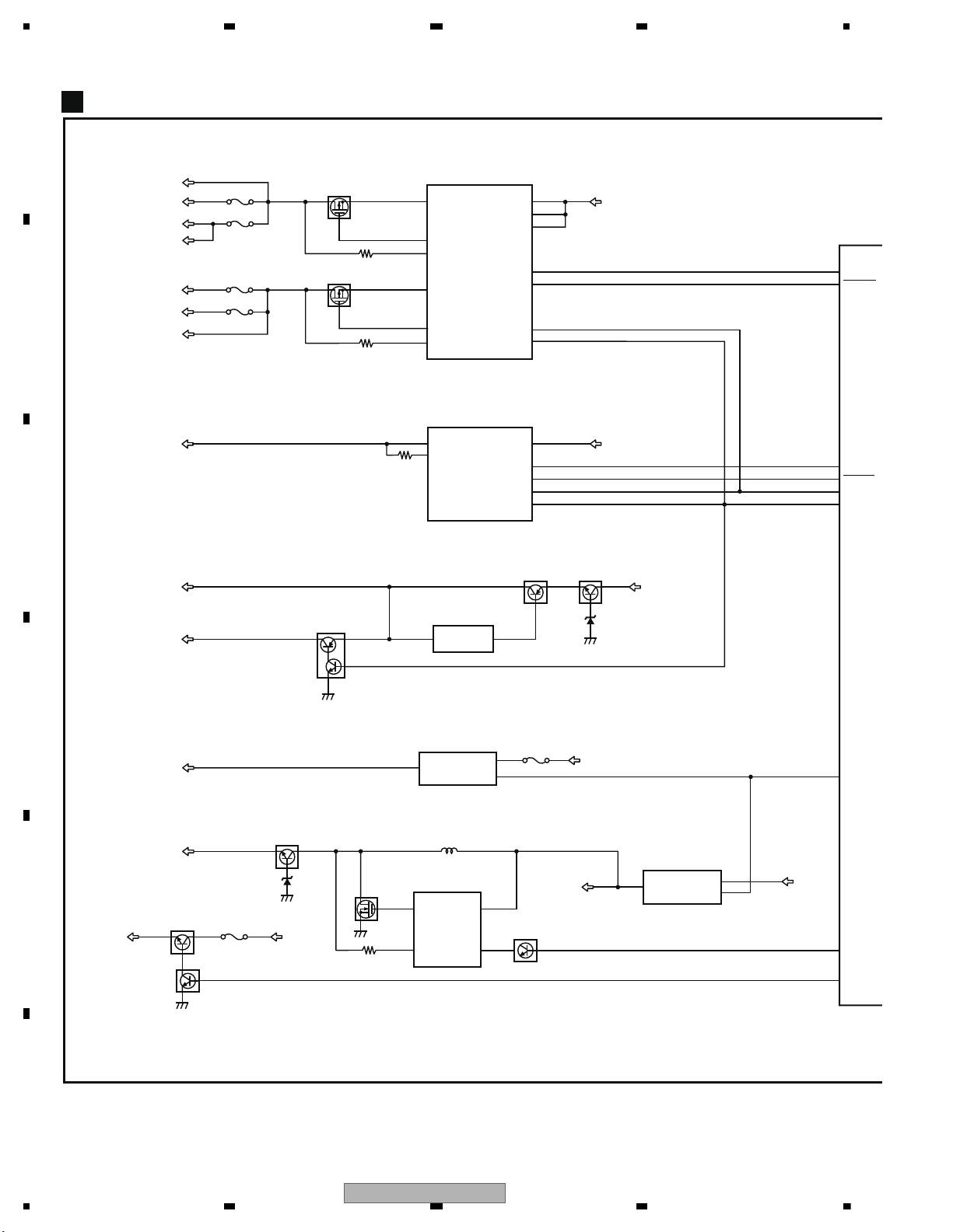
1234
1234
C
D
F
A
B
E
A
Q803
SYSPW
43
DDCCLK
DDCERR
USBFLG
92
45
46
65
USBCNT
VD5
114
113
VD8
TUN5
DD8
DD5
BUP_1VD8
P902
P1823
P1821
ILMB
PWRBL
P1822
VD5
P1951
PWRVI
P1971
4
2
TUN5V REG.
IC901
NJM2886DL3-05
VOUT
VIN
1
CONT
1
2
7
4
22
18
24
FB1
HSD1
3
RS1
Q951
Q852
Q952
HSD2
23
RS2
FB2
DC/DC CONVERTER
IC951
AN33012UA
VCC
8
EN1
9
EN2
12
FLAG
SYS+B
MOTV
23
Vout
Vin
VDD3.3V REG.
IC801
S-812C33AUA-C2N
1
4
IC802
NJM2388F84
CONTROL
VIN
SYS+B
USB5
VDD33
SWVDD
MOTV
EV12
MOTPWR2
DD8
13
SYNC
VCC_S1
VCC_S2
BUP_1
3
6
5
FB_USB
USBOUT
USB5V REG.
IC1851
OZ529IGN
VIN
12
EN_USB
9
FLT_USB
8
SYNC
4
EN_SYS
3
1
5
EaIn
Out
66
HIOUTCLK
EV12V REG.
IC851
TK11840L
VCC
7
OSC
Q1821
BUP_1
BUP_1
Q802
Q851
Q801
Q1822
Q853
DD8
SYS
P
I
135
VOUT
MOTHER PCB (2/2)
SWVDD
2
22
AVH-3400DVD/XUEW5
Page 23
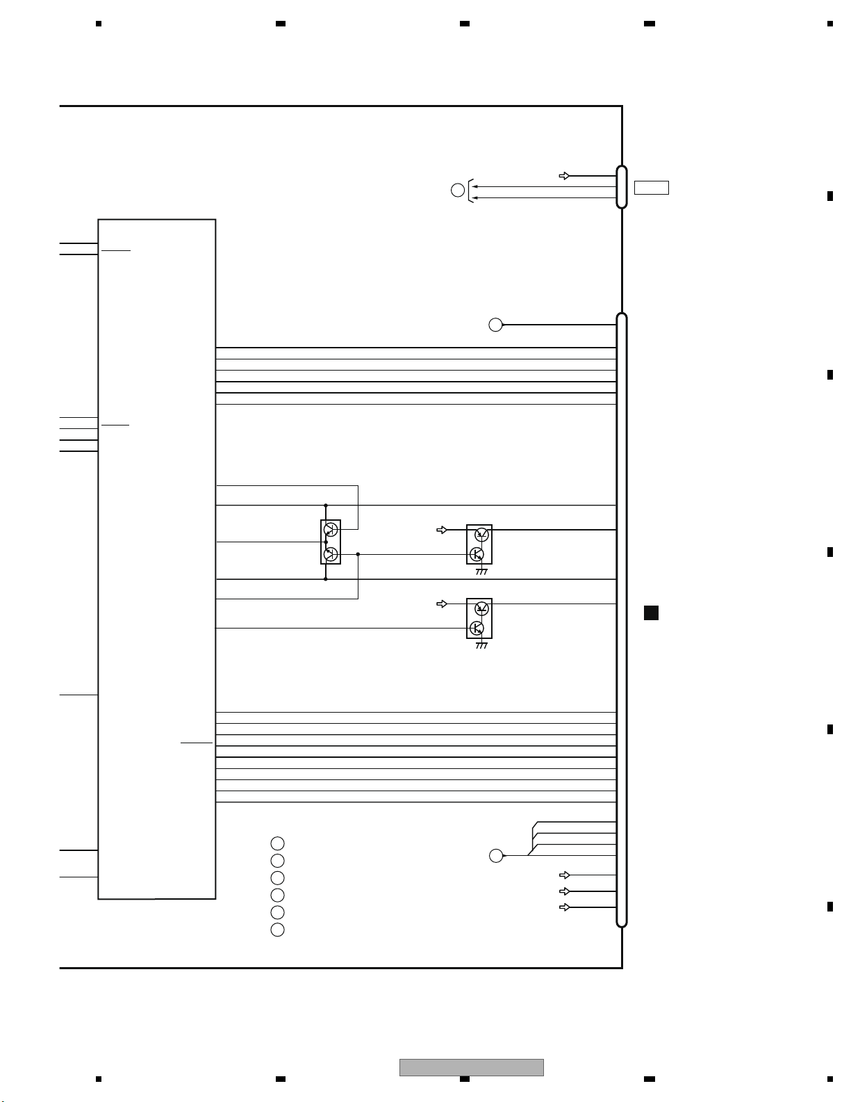
5 678
56
7
8
C
D
F
A
B
E
I
G
H
TO 1/2
TO 1/2
SYSPW
43
DDCCLK
DDCERR
USBFLG
92
45
46
65
USBCNT
VD5
114
113
VD8
MOTPWR2
66
HIOUTCLK
BUP_1
SYSTEM uCOM
PE5796A8
IC602(2/2)
JA571
USB_D-
USB_D+
D-
D+
KDT0
KDT1
B_PWM
REMIN
G_PWM
R_PWM
33
64
175
174
7
79
38
439LEDR
30
37
31
32
36
439LEDG
439LEDB
439KDT0
439KDT1
439REM
CN301
Q302
VDD33 39
42
ADVY
PLYV
Q303
41
ADVX
Q301
VDD33 40
PLXV
25
43
23
24
GtoS
GRST
PWGR
StoG
2
1
4
3
MBLPW
BLSYNC
TEMPSEN
DIMMER
5
BLERR
171
170
172
151
150
155
152
PNLADY
PNLADCRT
PNLVD
PNLADX
PNLYV
PNLXV
PWGR
97
99
173
81
139
83
166
98
TXMON
RXMON
MONIRST
TEMPSEN
DIMMER
MFLPW
BLSYNC
BLERR1
48
ILMB
27
PWRVI
50
l
6
PWRBL
8
l
18
19
20
21
ANAB
ANAR
CSYNC
ANAG
ANB
ANR
CSYNC
ANG
MONVBS
15
1
3
2
USB5V
USB5
TO 1/2
USB IF
CN5001
D
135
:AVH-3400DVD/XUEW5
:AVH-P3400DVD/XUUW5
:AVH-P3450DVD/XURC
:AVH-P3450DVD/XURD
:AVH-P3450DVD/XURI
:AVH-P3490DVD/XUID
A
B
C
D
E
F
AVH-3400DVD/XUEW5
23
Page 24
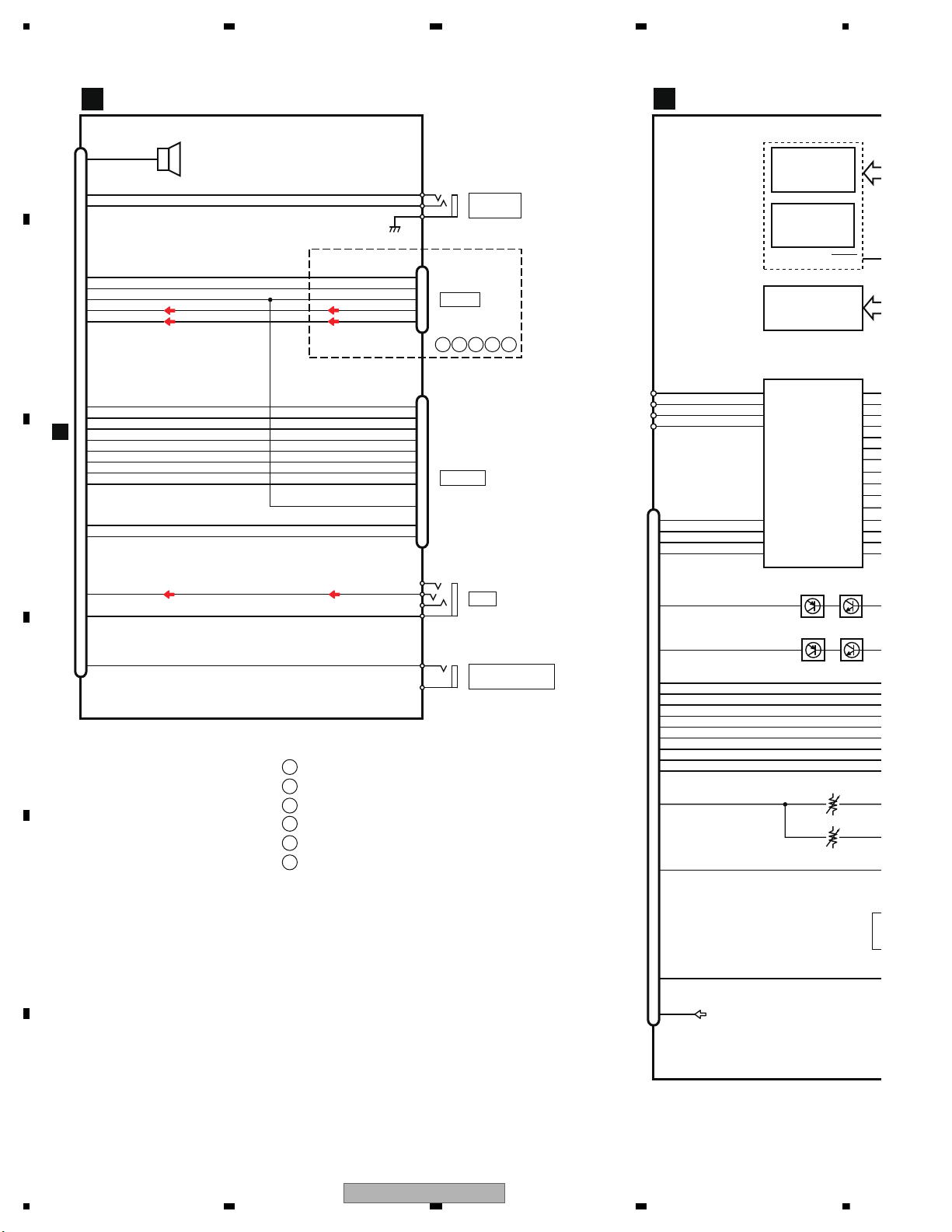
1234
1234
C
D
F
A
B
E
BCDEF
RESET
12
VCC5
PU (DP11)
SDRAM
IC1480
24
17
VO4+WHITE
14
VO2+
MOTOR DRIVER
IC1251
BA5839FP
OPINSL
23
OPOUTSL
27
OPIN3+
7
OPOUT1
2
OPIN2+
5
OPIN1+
22
LDIN
21
CNT
9
MUTE
1
T+
12
VO1+
2
F-
11
VO1-
3
F+
13
VO2-
4
T-
6
TEMP
10
F+H/G+H
16
B
17
A
18
C
19
D
20
FE1
21
FE2
11
E+G/E+F
13
78LD
14
65LD
9
VCC
CN1101
DVD CORE UNIT
C
VR1101
FLASH ROM (16M x 2)
IC1401
CWW5043
IC1402
CWW5044
LECRGM
18
VO4-GREEN
LECRGP
15
VO3+BLK
SPDLM
16
VO3-RED
SPDLP
6
OPIN1-
4
OPOUT2
25
OPOUT3
1
VR
23
RF
8
Vref
22
IMON
VR1102
Q1102Q1104
Q1101Q1103
T
1
JA2505
39
BEEP
38
WIRED
37
WIREDAD
34
BUS+
5
33
BUS-
8
32
ASENBO
11
14
BUSL-
7
13
BUSL+
BUS+
BUS-
ASENBO
BUSL-
BUSL+
CN2501
IF PCB
WIRED
REMOTE
JA2504
BZ2501
2
3
1
BACK CAMERA
INPUT
JA2502
2
1
JA2503
2
4
3
1
B
CN451
A
IP BUS
25
CN2502
31
NAVI_TO_SYS
24
30
SYS_TO_NAVI
21
29
GUIDEON
20
28
TVON
4
26
CSYNC
3
24
ANB
2
22
ANG
1
20
ANR
9
ASENBO
14
12
ONSEI- ONSEI-
13
11
ONSEI+
9
AUXL
5
AUXV
3
BCAMIN BCAMIN
BCAMGND
NAVI_TO_SYS
SYS_TO_NAVI
GUIDEON
TVON
CSYNC
ANB
ANG
ANR
ONSEI+
NAVI I/F
AUX
:AVH-3400DVD/XUEW5
:AVH-P3400DVD/XUUW5
:AVH-P3450DVD/XURC
:AVH-P3450DVD/XURD
:AVH-P3450DVD/XURI
:AVH-P3490DVD/XUID
1
GND
AUXL
AUXR
VIDEO
WIRED
GND
WIREDAD
BUZZER
3
OPIN2-
26
OPIN3-
A
B
C
D
E
F
M12L64164A-5TG2M
24
AVH-3400DVD/XUEW5
Page 25
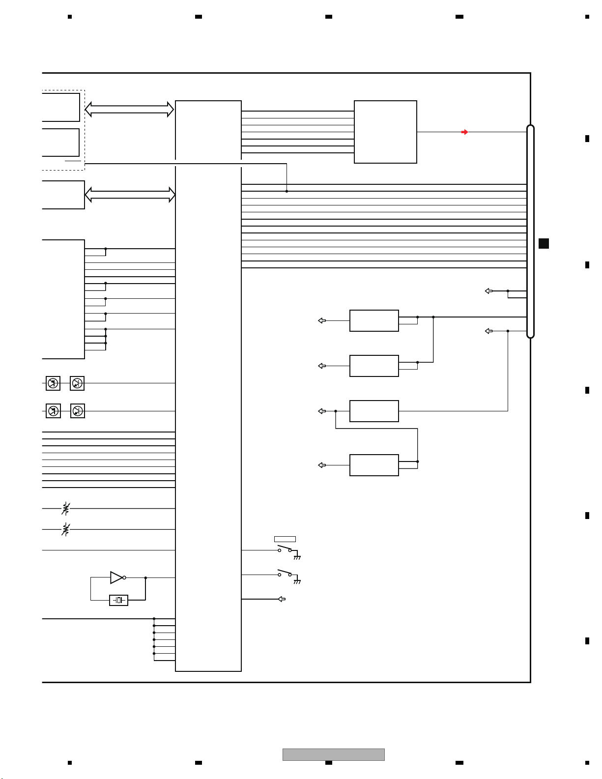
5 678
56
7
8
C
D
F
A
B
E
RESET
12
VD8
CN701
A
IC1480
24
IC1251
OPINSL
23
OPOUTSL
27
OPIN3+
7
OPOUT1
2
OPIN2+
5
OPIN1+
22
LDIN
21
CNT
9
MUTE
ANALOG LOUT
151
SYSTEM uCOM
IC1501
MN2DS0018MA
ADOUT
150
LRCK
14
AMUTE
23
XRESET
22
30
29
28
IRQPWR
21
HSTCMD
20
SLVSTS
19
STANBY
18
COMPOSITE
12
D-
9
D+
8
IECOUT
6
SCL
4
SDA
3
RESET
VD8
24
VD5
VCC5
2
CN1952
VR1101
7
ADAC
IC1801
PCM1753DBQ
VCC5 REG.
IC1002
VOUT
VIN
5
4
ON/OFF
3
S-1133B50-U5
VCC5_AU
VCC5-AU REG.
IC1003
VOUT
VIN
5
1
ON/OFF
3
S-1200B50-M5
VCC33
VCC33 REG.
IC1004
Vout
Vin
3
1
NJM2855DL1-33
VCC12
VCC12 REG.
IC1953
VOUT
VIN
1
6
ON/OFF
4
S-1135D12-A6
VOUTL
2
DATA
3
LRCK
149
SRCK
1
BCK
148
DACCK
16
SCK
57
SDODAC
13
MD
58
SCKDAC
14
MC
56
LTDAC
75
EXTRG1
70
NRES
48
IRQPWR
53
CMDCOMN
54
STSCOMN
191
STANDBY
138
COMPOSITE
144
LOUT
146
ROUT
152
IECOUT
47
I2C_SCL
46
I2C_SDA
65
HOME
61
CP_Reset
15
ML
67
CRGDRV
62
LDIN
63
CONT1
64
CONT2
6
OPIN1-
127
FD
4
OPOUT2
126
TD
25
OPOUT3
66
MD
1
VR
110
VHALF
122
TEMP
112
F+H_G+H
100
VIN3RF
99
VIN4RF
98
VIN2RF
97
VIN1RF
115
VIN7
116
VIN8
96
RFINP
109
VREFH
113
VIN5
114
VIN6
117
VIN3
118
VIN4
119
VIN2
120
VIN1
50
USB_CLOCK
105
CDMPD
VR1102
103
DVDMPD
111
E+G_E+F
106
LPCO2
104
LPCO1
Q1102
S1
55
12EJ
121
VDSENS
S3
Q1104
Q1101Q1103
42
TC7SZU04FU
IC1951
X1950
48MHz
HOME
3
OPIN2-
26
OPIN3-
VD8
AVH-3400DVD/XUEW5
25
Page 26
1234
1234
C
D
F
A
B
E
CN5001
X5801
9.597MHz
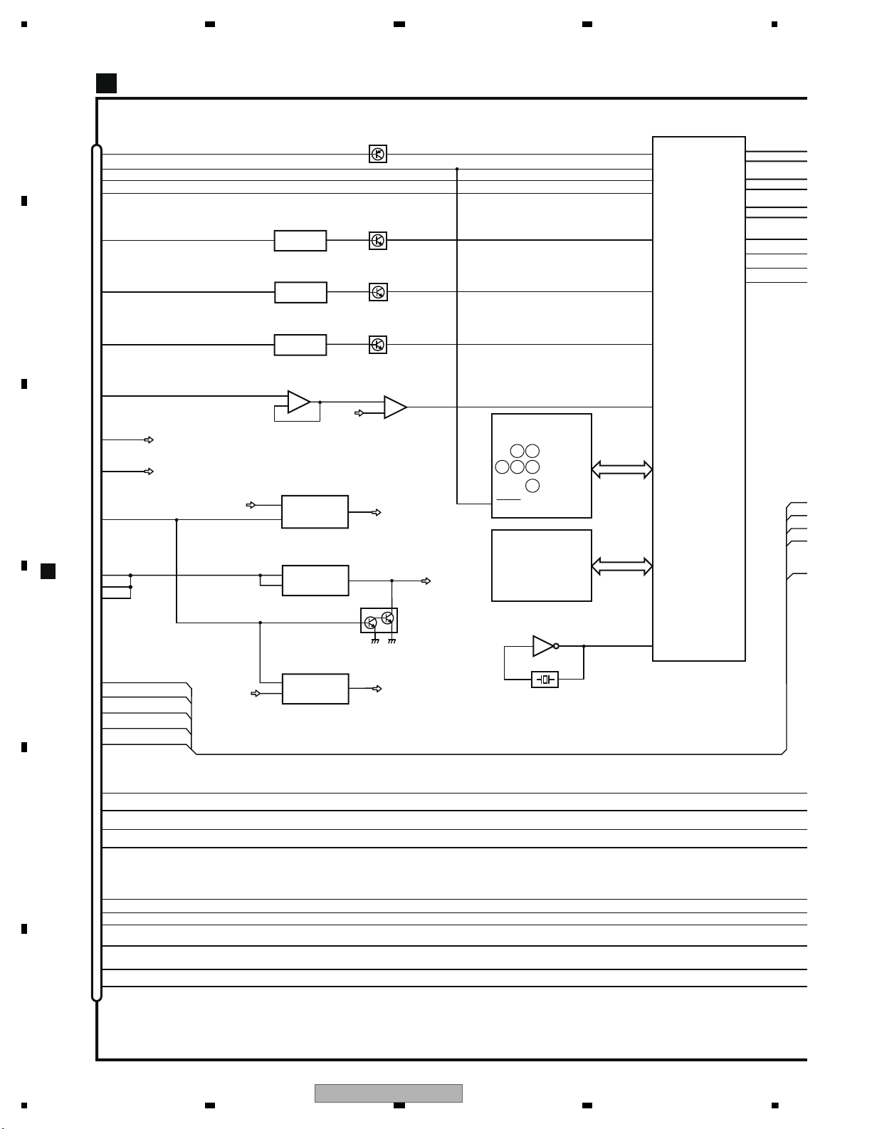
LCDOR [0-5]
LCDOG [0-5]
LCDOB [0-5]
LCD0C0
52
93
LCD0C1
92
GPIO9
87
LCD0CLK
88
MBL
AV0INB
GERDA-L
IC5802
MN103SH13
4
2
MONVBS
133
72
73
IC5803
TC7SHU04FUS1
LCDICLK
A
B
DE
:CXX4206
C :CXX4344
F
64M FLASH
IC5401
SERVICE UNIT (MONITOR)
36
PWRBL
ILMB
12
10
9
PLXV
CN301
11
I
43
45
DIM
TEM
135
Q5602
IC5801
S-24C04CI-K8U
28
27
26
GRST
GtoS
StoG
NRST
GPIO11
GPIO10
PLYV
ADVX
ADVY
8
PWGR
VIN
VOUT
1
IC5203
S-1200B55-M5
RGBVI
ON/OFF
PWRBL
RGBVI
5
3
BLC
48
47
49
46
BLERR
MBLPW
DIMMER
TEMPSEN
BLSYNC
50
D
IC5606
BH7673G
AMP(RED)
AV2IN
VD0VSY
31
ANAR
CSYNC
32
24
Q5605
-
+
4
1
3
RGBVI
IC5601
TC75S57FU
63
43
-
+
4
1
3
EEPROM
RESET
12
DIMPLS
TEMP1
BLCLK
VIN VOUT
4
1
IC5603
BH7673G
AMP(GREEN)
AV0INA
30
ANAG
Q5603
50
VIN VOUT
4
1
IC5604
BH7673G
AMP(BLUE)
AV1IN
33
ANAB
Q5604
57
VIN VOUT
4
1
IC5605
BU7485G
CSYNC
VCC34
Q5201
STBY
VOUT
1
IC5202
S-1135D12-A6
GD12V
PWRVI
GD1.2V REG.
4
BLE
20
19
439KDT0
21
439KDT1
439REM
14
13
15
439LEDB
439LEDG
439LEDR
VIN
3
VIN
VOUT
6
IC5201
S-1172B34-E6
VCC3.4V REG.
1
ON/OFF
3
3
2
1
BLERR1
A
VCC34
26
AVH-3400DVD/XUEW5
Page 27
5 678
56
7
8
C
D
F
A
B
E
PWRBL
LR[0-5]
LG[0-5]
LB[0-5]
|
18
23
|
25
30
|
32
37
13
14
39
16
CN5701
CN5301
VSYNC
93
HSYNC
92
SHUT
87
DCLK
88
MBLPW
LCD PANEL
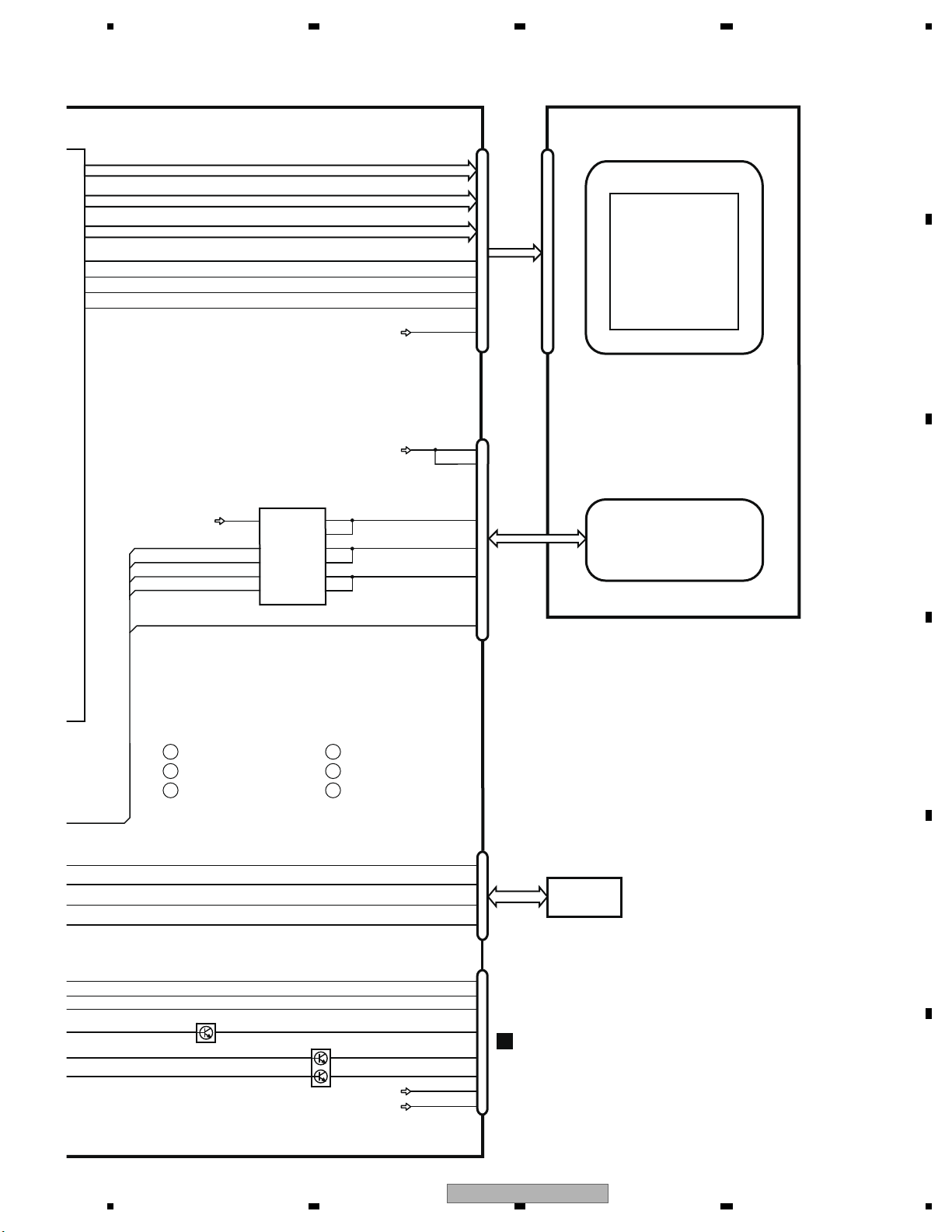
LCD
LCD BACKLIGHT
VCC
BLPWR
CN5101
VCC34
DIMPLS
TEMP1
SW
SYNC
ISEN1
IC5301
OZ527IRN
18
2
16
9
ENA
6
9
7
4
|
5
8
LCD BACKLIGHT DRIVER
8
ISEN2
LINE4
LINE2
LINE3
3
2
PWM
14
BLCLK
TEMPSEN
TOUCH
PLXV
PLYV
ADVX
ADVY
PANEL
PWRBL
STATUS
13
BLERR1
ISEN3
7
5
ISEN4
ISEN5
4
3
ISEN6
3
2
1
4
KDT0
KDT1
REM
8
3
10
Q5502
6
Q5501
5
4
VCC34
7
ILMB
2
LEDB1
LEDG1
LEDR1
CN3001
E
CN5501
:AVH-3400DVD/XUEW5
:AVH-P3400DVD/XUUW5
:AVH-P3450DVD/XURC
:AVH-P3450DVD/XURD
:AVH-P3450DVD/XURI
:AVH-P3490DVD/XUID
A
B
C
D
E
F
AVH-3400DVD/XUEW5
27
Page 28
1234
1234
C
D
F
A
B
E
CN431
A
CN5501
D
MOTV
1
2
6
14
OUT2
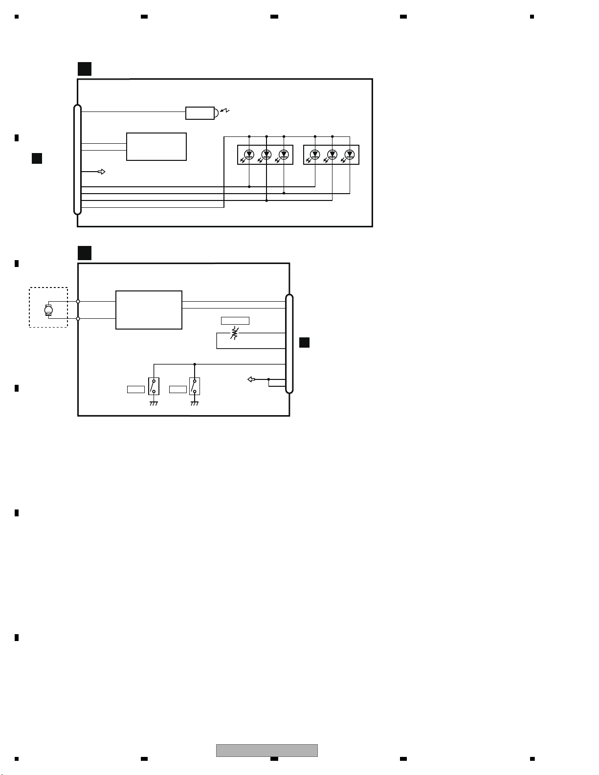
MOTOR DRIVER
IC101
BA6288FS
FIN
11
RIN
MOT1
MOT0GN
3
OUT1
PL
5
6
POS
7
VDD
H/O
8
10
CN101
10
REM 2
8
KDT0
7
VCC34
6
LEDB1
5
LEDG1
4
LEDR1
2
ILMB
CN3001
3
KDT1
M
MOTOR UNIT
EXA4003
PCB UNIT(SERVICE)
F
SERVICE UNIT (KEYBOARD)
E
DRIVE MECHA
VR101
S101
D3001 D3002
HOME
S102
HOME
POSITION
OUT
U3001
REMOTE CONTROL
SENSOR
KEY MATRIX
28
AVH-3400DVD/XUEW5
Page 29
5 678
56
7
8
C
D
F
A
B
E
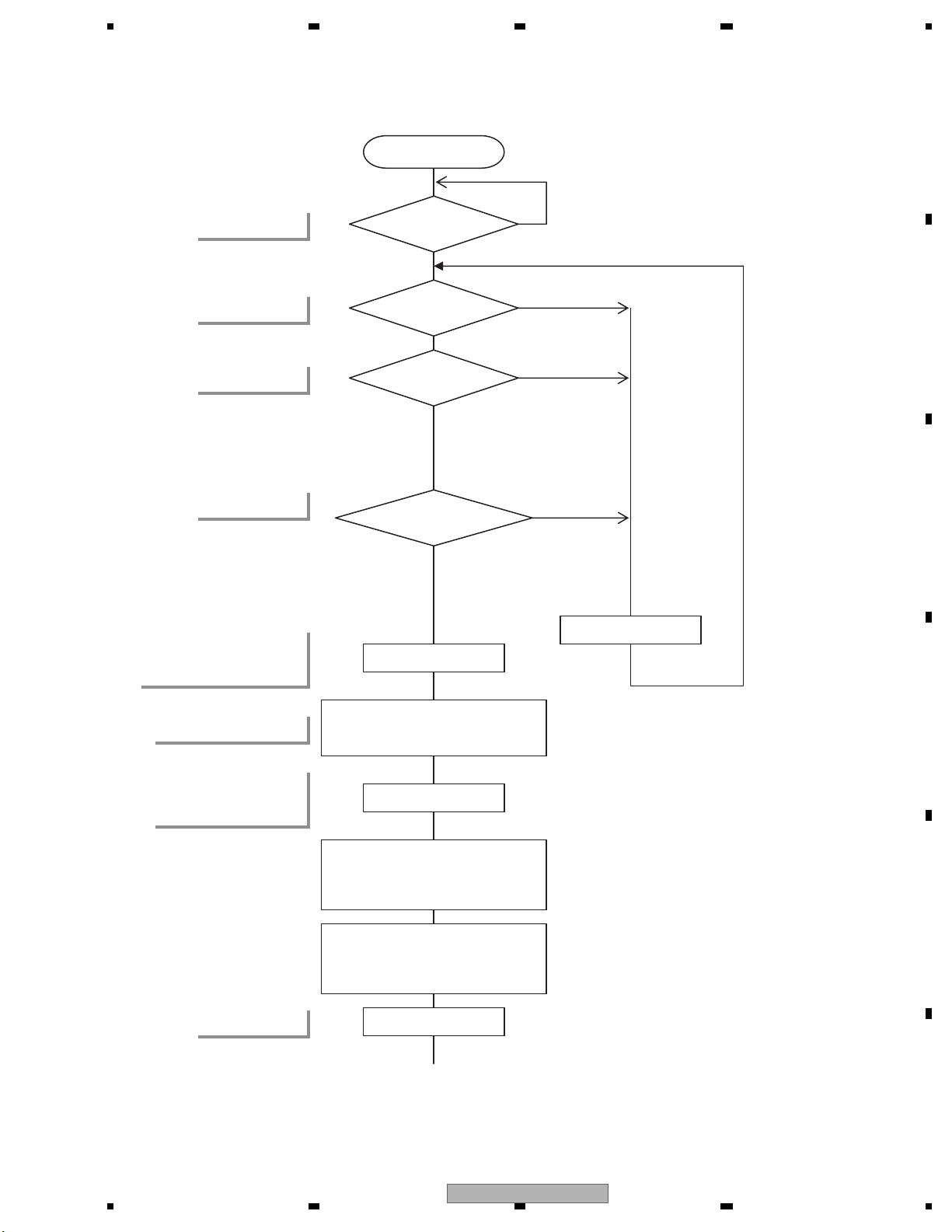
SYSPW←H
Source keys operate
Source ON
↓
Starts
Communication
with Display microcomputer
Vdd=3.3V?
BSENS=L?
ASENS=L?
ASENBO←H
VD5, 8←H
Y
Y
Y
Vdd : pin 15
BSENS : pin 82
ASENS : pin 80
ASENBO : pin 35
(UC Only)
VD5 : pin 113
DDCCLK : pin 92
DDCCLK←Clock Out
(Frequency of 413.9 kHz)
STANBY : pin 20
STANBY=H?
Standby
Y
VD8 : pin 114
RESET
SYSPW : pin 43
5. DIAGNOSIS
5.1 OPERATIONAL FLOWCHART
AVH-3400DVD/XUEW5
29
Page 30
1234
1234
C
D
F
A
B
E
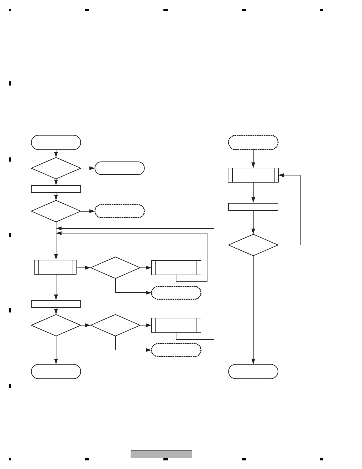
5.2 INSPECTION METHOD OF PICKUP UNIT
START
Is it OK?
Ckeck parts
other than PICK UP
PICK UP
cleaned?
Perform lens
cleaning
LD current check
Yes
No
Check1
Check2
Disc to be used
CD-DA : TCD-782
DVD-Video : TDV-582(GGV1025)
Exact judgment cannot be performed if the disk to be used has a crack and dirt.
Be careful of handling of a disk enough.
Execution method
Refer to the following page for the details of the check 1 and the check 2.
Finished
PU Lighting?
Please perform the
usual diagnosis.
No
Is it OK?
PICK UP
cleaned?
Perform lens
cleaning
Error rate check
Replace the
CRG chassis
Yes
Yes
Yes Yes
Yes
Yes
No
No No
No
No
Replace the
CRG chassis
Replace the
CRG chassis
RF level check
Check2
Error rate check
Is it OK?
RF level check
Replace the
CRG chassis
30
AVH-3400DVD/XUEW5
Page 31
5 678
56
7
8
C
D
F
A
B
E
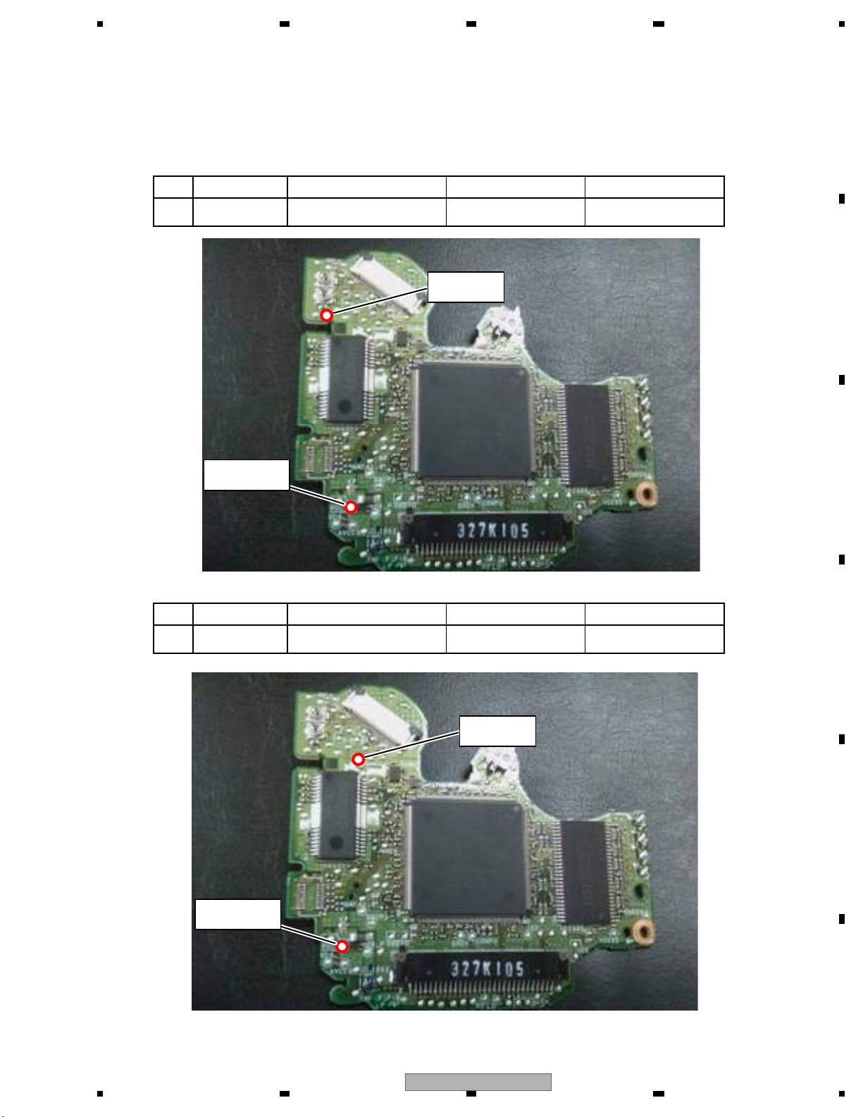
Check1 : LD current check
<Check>
Status: [Foucs closed] of TEST MODE
Notes: Please pay attention to the laser diode damage by static electricity.
Check Point
DVDLD1 - VCC5_PU
No.
1
Disc
GGV1025
Remarks: LD current
10 - 65 (mA)
Threshold
120 - 780 (mV)
CDLD1 - VCC5_PU2 TCD-782 10 - 60 (mA)150 - 900 (mV)
Check PointNo. Disc Remarks: LD currentThreshold
DVDLD1
VCC5_PU
CDLD1
VCC5_PU
AVH-3400DVD/XUEW5
31
Page 32
1234
1234
C
D
F
A
B
E
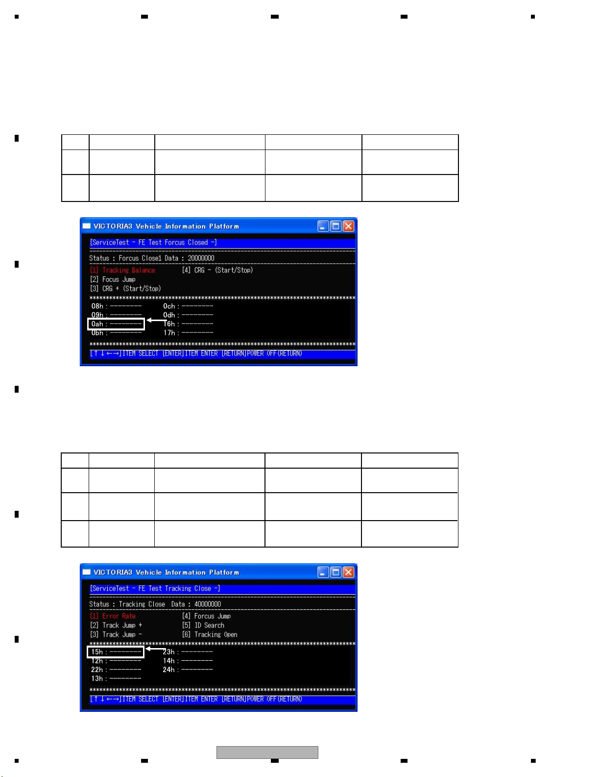
Check : RF level
<Check>
ASMAX value shows the value of RF level.
Status: [Foucs closed] of TEST MODE
Check Point
8 digits value of
ASMAX on display
No.
1
Disc
GGV1025
Remarks
Threshold
more than
0000 0B00
2 TCD-782
more than
0000 0E00
Check2 : Error rate check
<Check>
Status: [Tracking Closed] of TEST MODE
ID:40000
1
GGV1025
less than
1.000E-3
2
GGV1025
3 TCD-782
ID:200000
less than
1.000E-3
ID:HOME Position
less than
2.500E-3
8 digits value of
ASMAX on display
Check Point
No.
Disc
Remarks
Threshold
32
AVH-3400DVD/XUEW5
Page 33
5 678
56
7
8
C
D
F
A
B
E
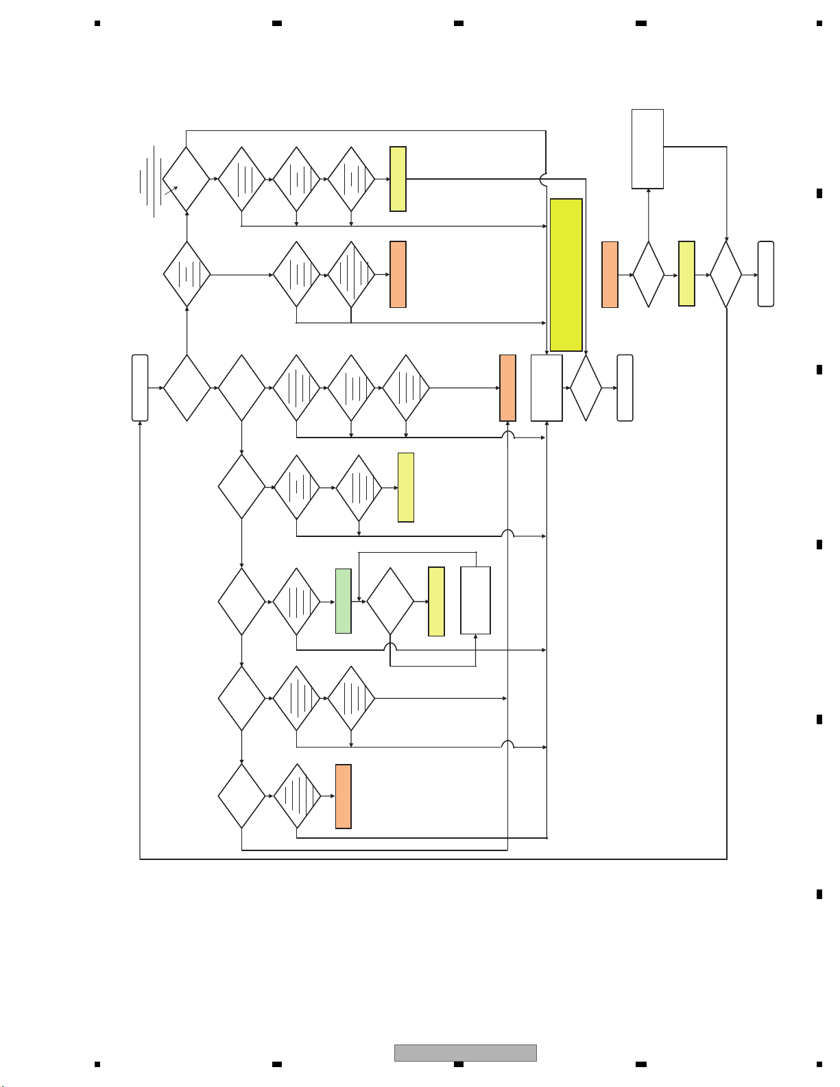
Is the image
in error?
Go to FE related
repair process.
Is VD8,
VCC5 power
supply voltage OK?
Execute
check 7.
Is AVCC5
voltage OK?
Execute
check 8.
Standby
OK?
Execute
check 1.
Is VDD5
(VCC33, VCC12)
power supply voltage OK?
Execute check 2.
Can the
playback
start?
Is SDRAM
IF OK?
Execute
check 6.
Is DACCLK
normal?
Execute
check 9.
Is the audio
circuit OK?
Execute
check 10.
Is the video
circuit OK?
Execute
check 11.
Repair the
defective part.
*1)Note
Normal?
NO
YES
YES
YES
Is AVCC5
voltage OK?
Execute
check 8.
Reset OK?
Execute
check 3.
Is VSENS
OK?
Execute
check 4.
YES
YES
YES
YES
YES
YES
YES
Go to FE
section check.
YES
YES
NO
NO
NO
Go to FE
section check.
NO
Replace the unit.
YES
YES
Normal?
YES
Go to FE
section check.
Is 27 MHz
OK?
Execute
check 5.
NO
YESYES
START
END
END
Is FE section
normal?
Replace the unit.
YES
Go to FE
section check.
NO
NO
NO
Does the
operation
take time?
Is the
life of flash
memory OK?
Conduct check
item 12.
YES
YES
NO
NO
Is the sound
in error?
Is the
USB play
in error?
Is the iPod play
in error?
Is 48 MHz
OK?
Execute
check 13.
Is the USB
circuit OK?
Execute
check 14.
Is the iPod
circuit OK?
Execute
check 14.
Go to the
product check.
The product
is normal?(iPod
attestation IC)
YES
YES
Product repair
YES
NO
NO
NO
NO
YES
NO
YES
Replace the unit.
YES
Replace the unit.
YES
NO
NO
*1) With service, even when exchange of a flash ROM
is required, please replace core unit .
(Since the key etc. are not written in in case of the
flash simple substance)
LS2 BACK END section flow
NO
NO
NO
NO
NO
5.3 DIAGNOSIS FLOWCHART
AVH-3400DVD/XUEW5
33
Page 34
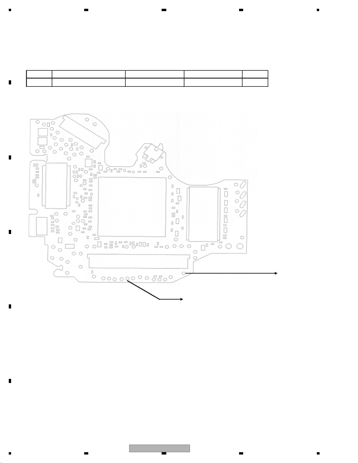
1234
1234
C
D
F
A
B
E
Check 1: Standby OK?
<Check> Check the voltage at the “STANBY” test point while the power is on.
Use the “DGND1” test point at the reference.
No. Check point Module No. Specification value Unit
1 STANBY - DGND1 ALL
V
Side A
Fig 1.1: STANBY check point
GNDD1
STANBY
VCC33 - 0.6 V or more
34
AVH-3400DVD/XUEW5
Page 35
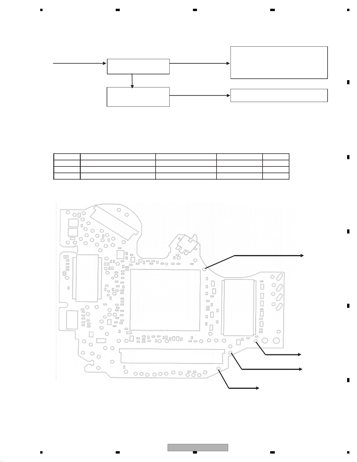
5 678
56
7
8
C
D
F
A
B
E
Check 2: Is VDD5 (VCC33, VCC12) power supply voltage OK?
IC1401 FLASH power supply (Data)
VDD5 VCC33 (= 3.3V )
IC1004
3.3 V output regulator
IC1953
1.2 V output Regulator
VCC12 (= 1.2V )
IC1402 FLASH power supply (Program)
IC1480 SDRAM power supply
IC1501 DV5 power supply
IC1501 DV5 power supply
Fig 2.1: Power supply configuration
<Check> Check the voltage at the “VDD5_1, VCC33_1 and VCC12_1” test point while the power is on.
Use the “DGND1” test point at the reference.
No. Check point Module No. Specification value Unit
1
2
3
VDD5_1 - DGND1
VCC33_1 - DGND1
VCC12_1 - DGND1
ALL 5.0 ± 0.4 V
ALL 3.3 ± 0.033 V
ALL 1.2 ± 0.015 V
Side A
Fig 2.2: VDD5, VCC33, VCC12 voltage check points
VCC12
VCC33
VD5-1
DGND1
AVH-3400DVD/XUEW5
35
Page 36
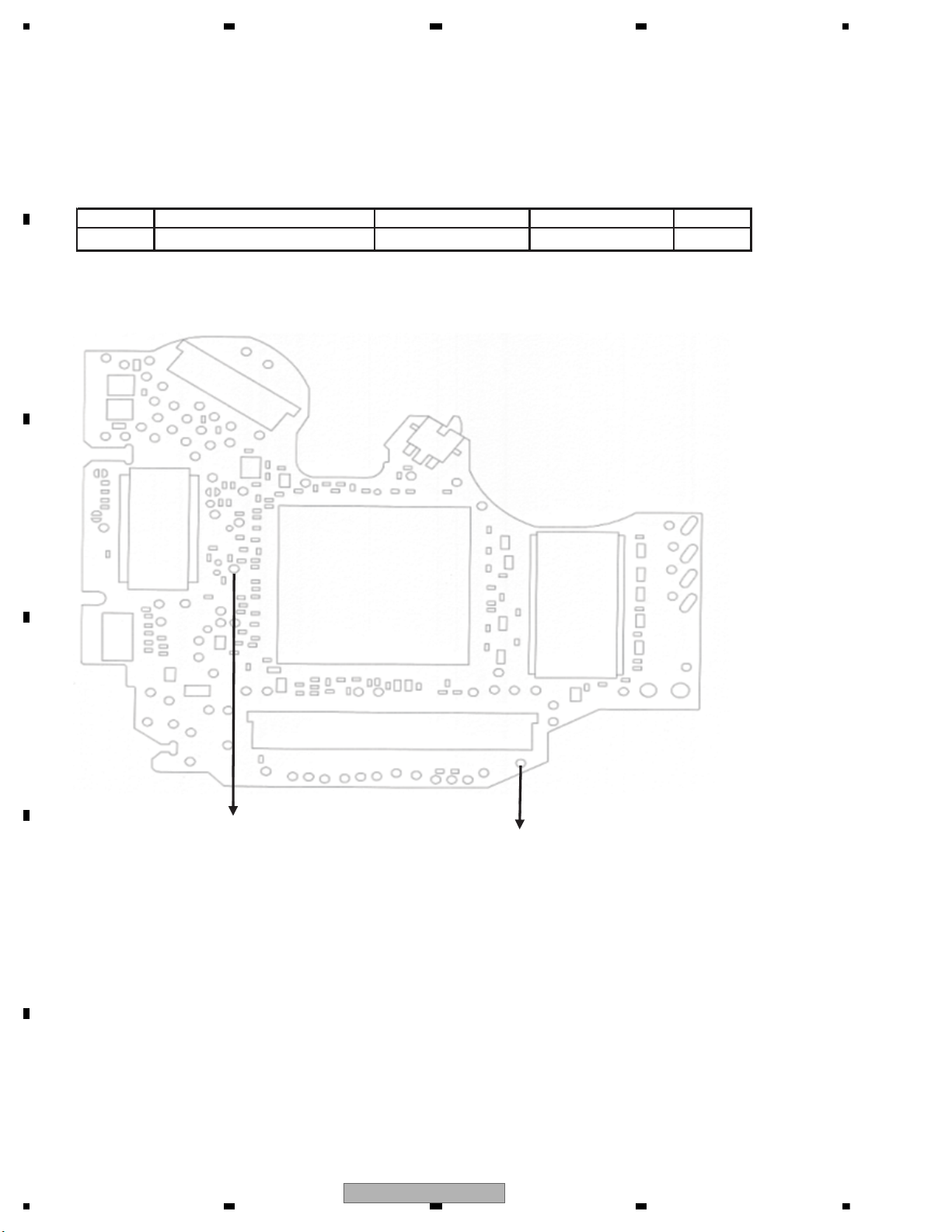
1234
1234
C
D
F
A
B
E
Check 3: Reset OK?
<Check> Check the voltage at the “XRES” test point while the power is on.
Use the “DGND1” test point at the reference.
No. Check point Module No. Specification value Unit
1 NRES - DGND1 ALL VCC33 × 0.7 or more V
Side A
Fig 3.1: RESET check point
NRES
DGND1
36
AVH-3400DVD/XUEW5
Page 37
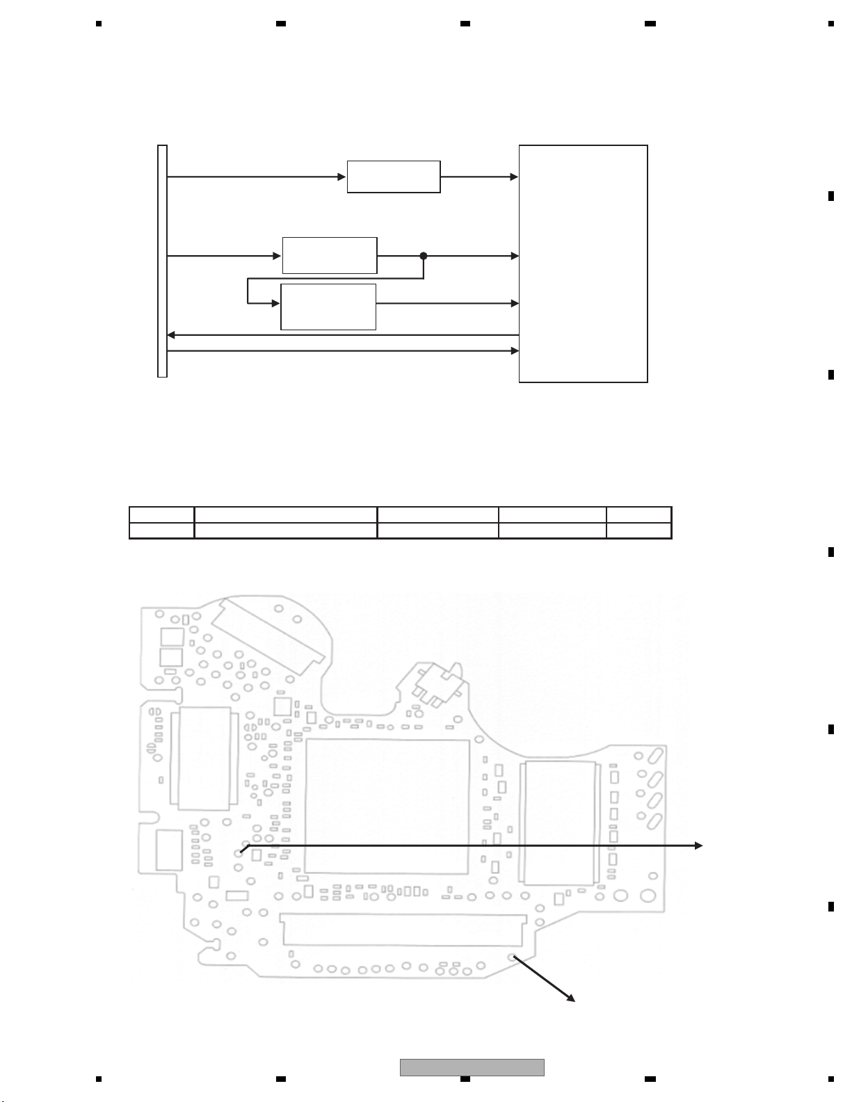
5 678
56
7
8
C
D
F
A
B
E
Check 4: Is VSENS OK?
CN1952
HOST I/F
IC1501
VD8
VDD5 VCC33
STANBY
NRES
IC1004
Regulator
IC1953
1.2 V output
Regulator
R1004
R1007
VCC12
VSENS
DV5
Fig 4.1: Power supply configuration and VSENS
<Check> Check the voltage at the “VSENS” test point while the power is on.
Use the “DGND1” test point at the reference.
No. Check point Module No. Specification value Unit
1 VSENS - DGND1 ALL 0.95 - 1.07 V
VD8 = 8.0 ± 0.4 V
Side A
VSENS
Fig 4.2: VSENS check point
AVH-3400DVD/XUEW5
DGND1
37
Page 38
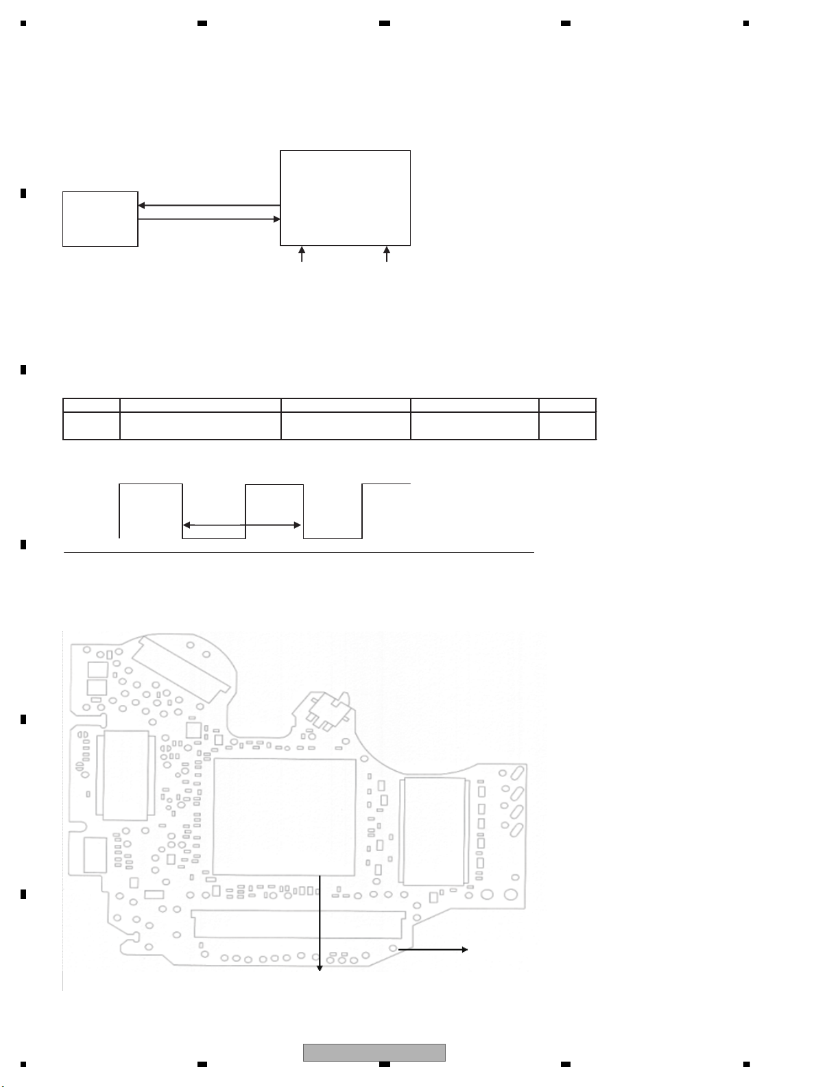
1234
1234
C
D
F
A
B
E
Check 5: 27 MHz Normal?
<Outline> Each clock is created inside the IC1501 using the 27 MHz master crystal oscillator (X1501).
OSCO
OSCI
Fig 5.1: Clock configuration
<Check method> Turn the power on, and check with DGND being the reference.
In case of NG, check the applicable line, periphery of IC1501,
soldering of the peripheral components and defective components.
No. Check point Module No. Specification value Unit
2 IC1501 156pin - DGND1 ALL
27 MHz ± 50 ppm
ppm
GND
Fig 5.2: Clock specification value
Side A
Fig 5.3: 27 MHz check point
IC1501
DVD-LSI
X1501
27 MHz
crystal
VCC33 VCC12
Specification
value
IC1501 156pin
DGND1
38
AVH-3400DVD/XUEW5
Page 39
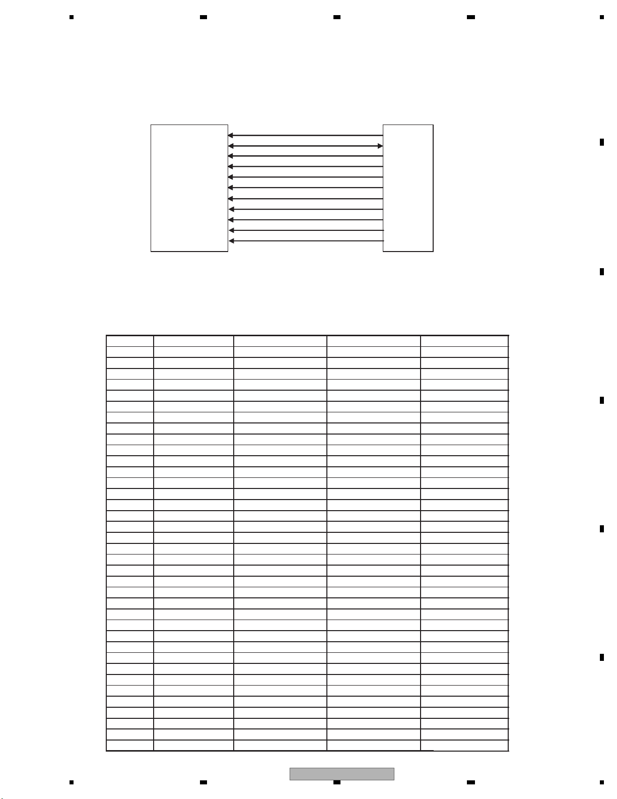
5 678
56
7
8
C
D
F
A
B
E
Check 6: Is SDRAM I/F OK?
<Outline> In order to secure the MPEG stream data as the buffer,
the capacity of communication I/F SDRAM between the LSI and the memory is 64Mbit.
Be careful as XCSM, XWE, XCAS and XRAS of IC1480 are called differently in IC1501,
namely NCSM, NWE, NCAS, NRAS.
IC1480
SDRAM
MA0 - 11
MDQ0 - 15
MCK
IC1501
DV5
XWE(NWE)
XCAS(NCAS)
XRAS(NRAS)
XCSM(NCSM)
DQM0
DQM1
BA0
BA1
Fig 6.1: SDRAM I/F
<Check> Check the conductivity at “check point 1” and “check point 2” without power.
In case of NG, check the soldering and defective components throughout the
“output t input” of the applicable section.
No. Signal name Check point 1 Check point 2 Specification value
1 MA0 IC1480 23pin IC1501 201pin 56 ohm ± 5%
2 MA1 IC1480 24pin IC1501 203pin 56 ohm ± 5%
3 MA2 IC1480 25pin IC1501 207pin 56 ohm ± 5%
4 MA3 IC1480 26pin IC1501 209pin 56 ohm ± 5%
5 MA4 IC1480 29pin IC1501 208pin 56 ohm ± 5%
6 MA5 IC1480 30pin IC1501 206pin 56 ohm ± 5%
7 MA6 IC1480 31pin IC1501 202pin 56 ohm ± 5%
8 MA7 IC1480 32pin IC1501 200pin 56 ohm ± 5%
9 MA8 IC1480 33pin IC1501 198pin 56 ohm ± 5%
10 MA9 IC1480 34pin IC1501 194pin 56 ohm ± 5%
11 MA10 IC1480 22pin IC1501 199pin 56 ohm ± 5%
12 MA11 IC1480 35pin IC1501 192pin 56 ohm ± 5%
13 MDQ0 IC1480 2pin IC1501 160pin 56 ohm ± 5%
14 MDQ1 IC1480 4pin IC1501 162pin 56 ohm ± 5%
15 MDQ2 IC1480 5pin IC1501 164pin 56 ohm ± 5%
16 MDQ3 IC1480 7pin IC1501 168pin 56 ohm ± 5%
17 MDQ4 IC1480 8pin IC1501 170pin 56 ohm ± 5%
18 MDQ5 IC1480 10pin IC1501 172pin 56 ohm ± 5%
19 MDQ6 IC1480 11pin IC1501 176pin 56 ohm ± 5%
20 MDQ7 IC1480 13pin IC1501 178pin 56 ohm ± 5%
21 MDQ8 IC1480 42pin IC1501 177pin 56 ohm ± 5%
22 MDQ9 IC1480 44pin IC1501 175pin 56 ohm ± 5%
23 MDQ10 IC1480 45pin IC1501 171pin 56 ohm ± 5%
24 MDQ11 IC1480 47pin IC1501 169pin 56 ohm ± 5%
25 MDQ12 IC1480 48pin IC1501 167pin 56 ohm ± 5%
26 MDQ13 IC1480 50pin IC1501 163pin 56 ohm ± 5%
27 MDQ14 IC1480 51pin IC1501 161pin 56 ohm ± 5%
28 MDQ15 IC1480 53pin IC1501 159pin 56 ohm ± 5%
29 MCK IC1480 38pin IC1501 183pin 47 ohm ± 5%
30 XWE IC1480 16pin IC1501 181pin 56 ohm ± 5%
31 XCAS IC1480 17pin IC1501 188pin 56 ohm ± 5%
32 XRAS IC1480 18pin IC1501 189pin 56 ohm ± 5%
33 XCSM IC1480 19pin IC1501 190pin 56 ohm ± 5%
34 DQM0 IC1480 15pin IC1501 179pin 56 ohm ± 5%
35 DQM1 IC1480 39pin IC1501 180pin 56 ohm ± 5%
36 BA0 IC1480 20pin IC1501 193pin 56 ohm ± 5%
37 BA1
IC1480 21pin IC1501 197pin
56 ohm ± 5%
AVH-3400DVD/XUEW5
39
Page 40
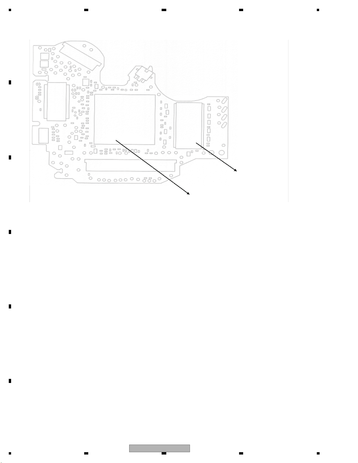
1234
1234
C
D
F
A
B
E
Side A
Fig 6.2: SDRAM I/F check point
Check point 2 (IC1501)
Check point 1 (IC1480)
40
AVH-3400DVD/XUEW5
Page 41
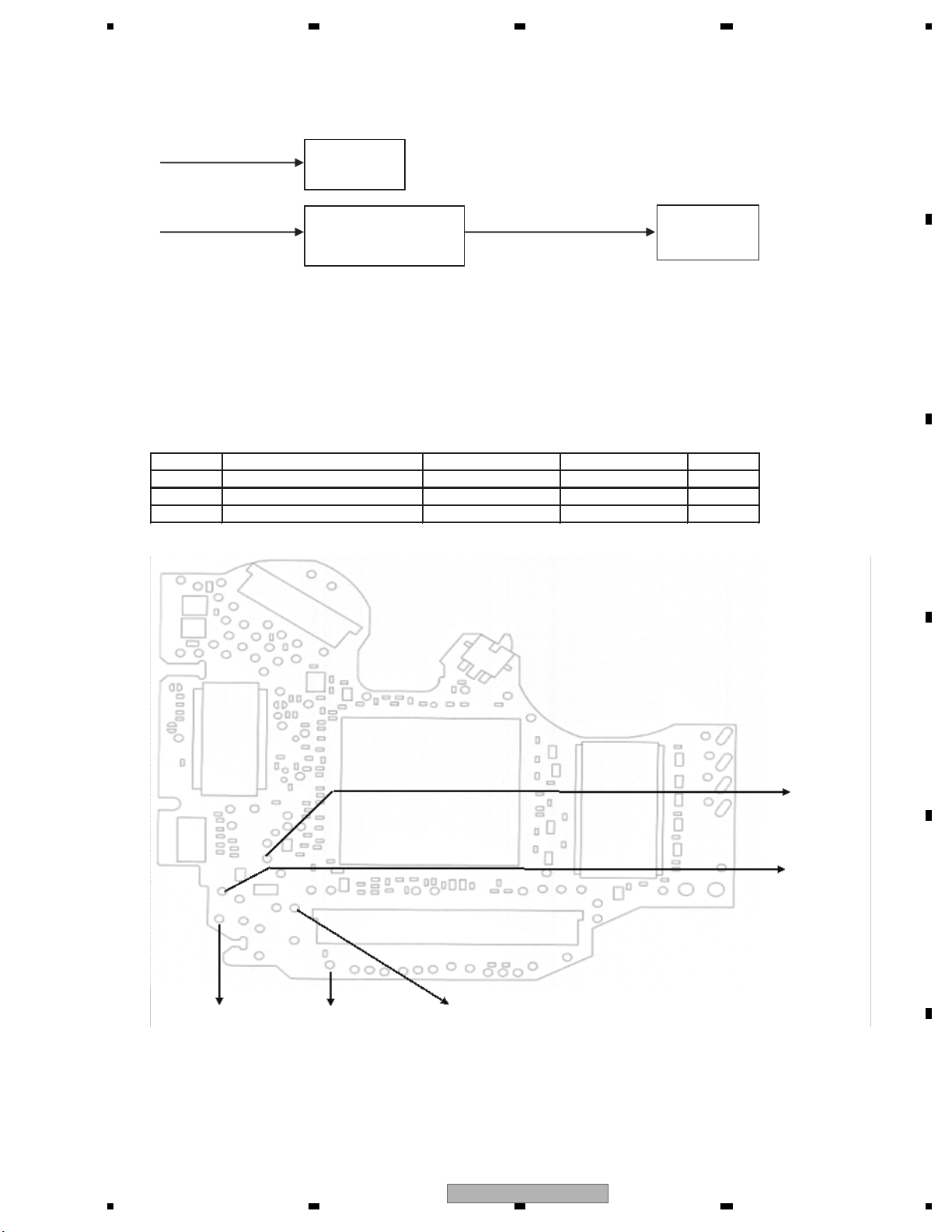
5 678
56
7
8
C
D
F
A
B
E
Check 7: Is VD8, VCC5 power supply voltage OK?
VD8_1
F.E. driver
system
VD8_2
REG IC
for VCC 5 V.
VCC5 (= 5.0 V )
Power supply
for PU
Fig 7.1: Power supply configuration
<Check> Check the voltage at the “VD8_P, VD8_A and VCC5_1” test point while the power is on.
Use the “PGND1 and AGND1” test point at the reference.
No. Check point Module No. Specification value Unit
VD8_P - PGND1
1
VD8_A - AGND1
2
VCC5_1 - AGND1
3
ALL 8.0 ± 0.4 V
ALL 8.0 ± 0.4 V
ALL 5.0 ± 0.05 V
Side A
VD8_A
VD8_P
Fig 7.2: VD8, VCC5 voltage check points
AGND1
VCC5_1
PGND1
AVH-3400DVD/XUEW5
41
Page 42
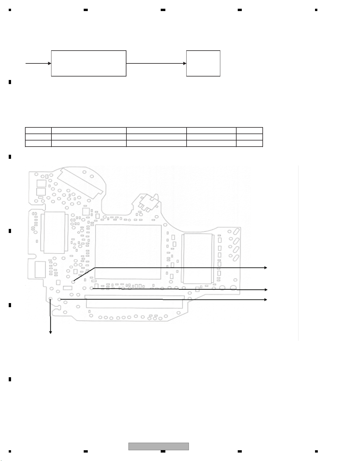
1234
1234
C
D
F
A
B
E
Check 8: Is AVCC5 voltage OK?
VD8
AVCC5 (= 5.0 V )
Fig 8.1: Power supply configuration
<Check> Playback DVD-REF-A1 TITLE 1 and check the voltage at the stylus.
Check with PGND_3 and GNDAU1 being the reference.
No. Check point Module No. Specification value Unit
1
VD8_A - PGND_3
ALL 8.0 ± 0.4 V
2
AVCC5 - GNDAU1
ALL 5.0 ± 0.05 V
Side A
Fig 8.2: VD8, AVCC5 voltage check points
IC1801
Audio-DAC
IC1003
REG IC
for AVCC 5 V.
PGND3
GNDAU1
AVCC5
VD8_A
42
AVH-3400DVD/XUEW5
Page 43
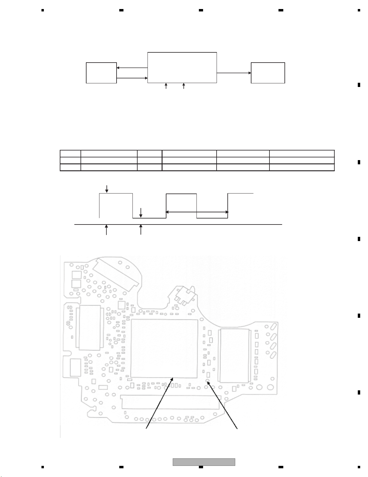
5 678
56
7
8
C
D
F
A
B
E
Check 9: Is DACCLK normal?
<Outline> DACCLK for Audio-DAC is created by IC1501 using the 27 MHz master crystal oscillator (X1501).
X1501
27MHz
crystal
IC1501
DVD-LSI
DACCLK
IC1801
Audio-DAC
VCC33
VCC12
Fig 9.1: Clock configuration
<Check method>
DVD: DVD-REF-A1 TITLE 1
CD: Playback a normal CDDA.
Common to all DVD-V compatible modules.
Check with DGND being the reference.
In case of NG, check the applicable line, the periphery of IC1501, soldering of the peripheral components and
defective components.
No.
Check point 1 (stylus)
Media Specification value 1 Specification value 2 Specification value 3
1 DACCK DVD 2.0 V - VCC33V DGND - 0.8 V 36.8640 MHz ± 300 ppm
2 DACCK CD 2.0 V - VCC33V DGND - 0.8 V 33.8688 MHz ± 300 ppm
Specification
value 1
Specification
value 2
Specification
value 3
GND
Fig 9.2: Clock specification value
Side A
Check point 2 (IC1501 148 pin)
Fig 9.3: DACCLK check point
DGND4
AVH-3400DVD/XUEW5
43
Page 44
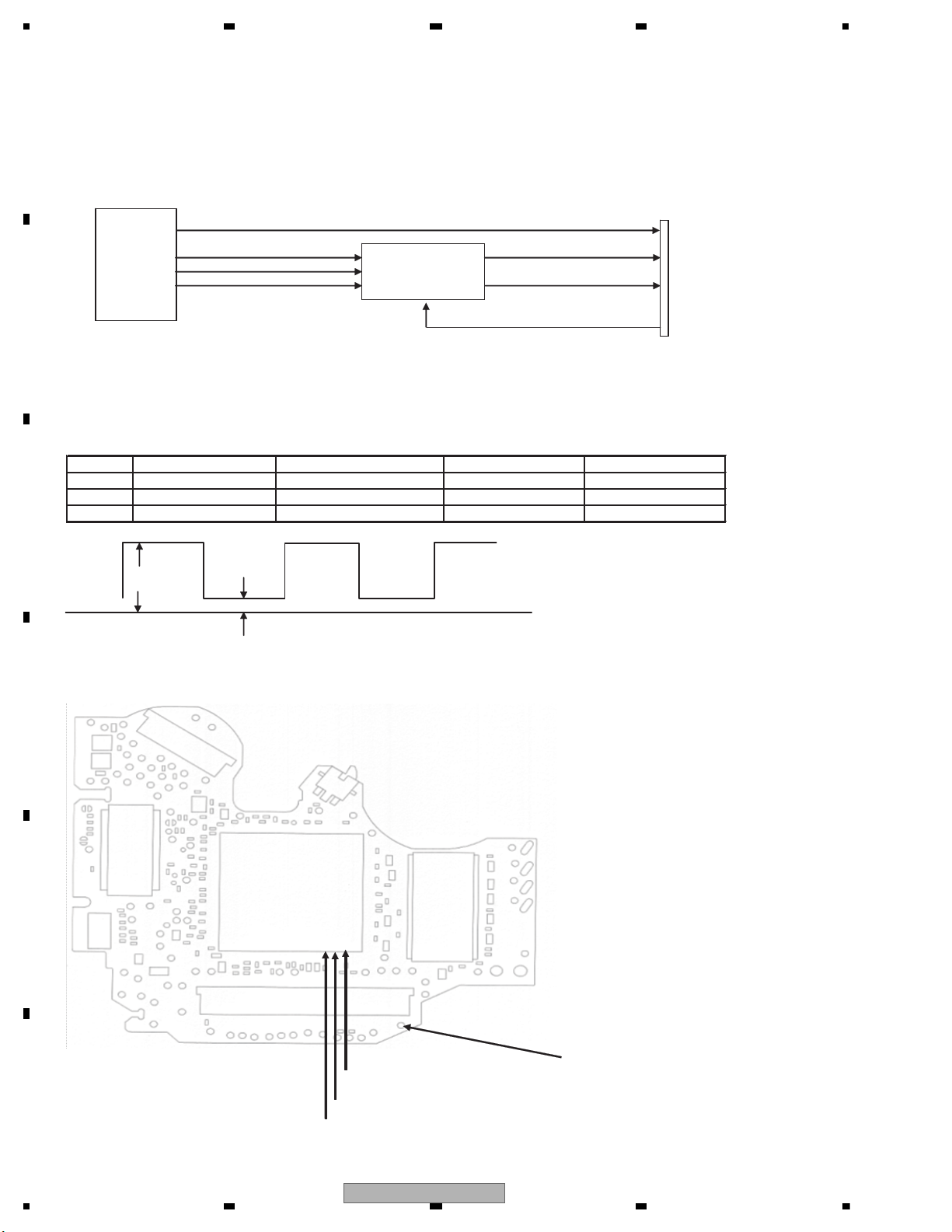
1234
1234
C
D
F
A
B
E
Check 10: Is the audio circuit OK?
<Outline> The serial 3 lines digital output + DACCLK, output from DVD-LSI (IC1501), are converted to analog audio
signal at Audio-DAC (IC1801) and are output from the HOST I/F (CN1952).
Simultaneously, the analog MUTE signal is also output from DVD-LSI (IC1501) via the HOST I/F.
The digital audio signal (IECOUT), output from DVD-LSI (IC1501).
CN1952
HOST I/F
IECOUT
LRCK LO
ADOUT
SRCK RO
GNDAU
Fig 10.1: Audio circuit
<Check method> Playback DVD-REF-A1 TITLE 2 CHAPTER 1 (48 k/16 bit 1 kHz 0 dB),
and check with DGND1 being the reference.
In case of NG, check the applicable line, periphery of major components as described in the above drawing,
soldering of the peripheral components and defective components.
No. Check point 1 (stylus) Specification value 1 Specification value 2 Reference waveform
1 ADOUT VCC33V - 0.6 V or higher 0.4 V or lower Waveform 1
2 SRCK VCC33V - 0.6 V or higher 0.4 V or lower Waveform 2
3 LRCK VCC33V - 0.6 V or higher 0.4 V or lower Waveform 3
GND
Fig 10.2: Serial 3 lines specification value
Side A
Fig 10.3: Serial 3 lines check points
IC1801
Audio-DAC
IC1501
DVD-LSI
Specification
value 1
Specification
value 2
149pin SRCK signal
150pin LRCK signal
151pin ADOUT signal
DGND1
44
AVH-3400DVD/XUEW5
Page 45
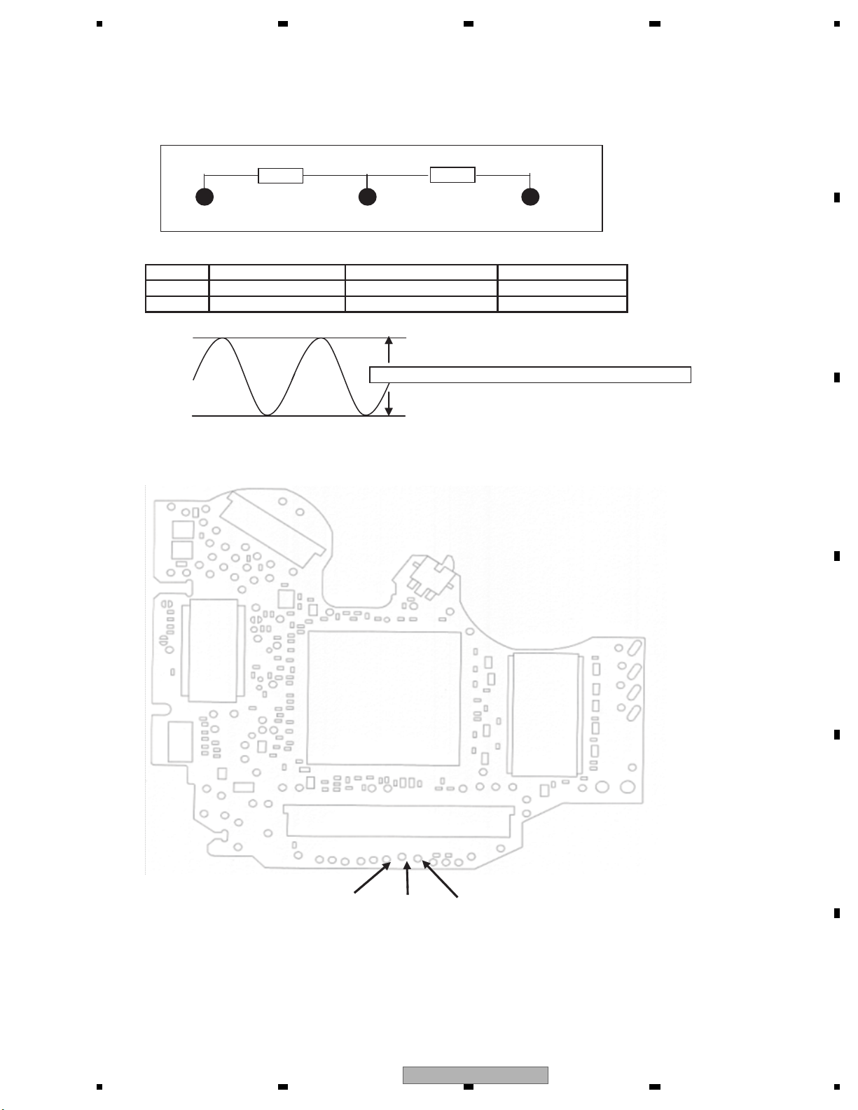
5 678
56
7
8
C
D
F
A
B
E
The following checks shall be conducted using the following measurement circuits with GNDAU1 being the reference.
47 kohm
47 kohm
LO ROGNDAU1
No. Check point 1 (stylus)
4 LO 1400 ± 150 mV Waveform 4
5 RO 1400 ± 150 mV Waveform 4
Specification value (rms)
Reference waveform
Specification value is the root-mean-square value (rms).
Fig 10.4: Analog audio out (LO, RO) specification value.
Side A
GNDAU3
Fig 10.5: Analog audio out check point
LORO
AVH-3400DVD/XUEW5
45
Page 46
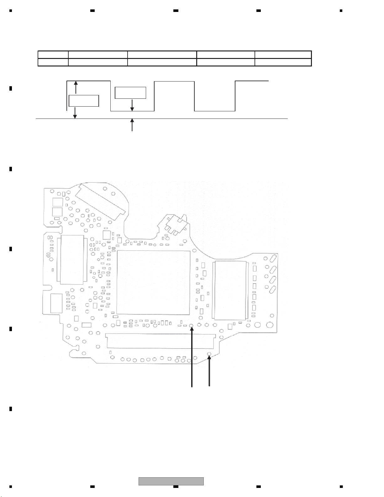
1234
1234
C
D
F
A
B
E
Check with DGND1 being the reference.
No. Check point 1 (stylus) Specification value 1 Specification value 2 Reference waveform
6 IEC VCC33V - 0.6 V or higher 0.4 V or lower Waveform 5
10.6: Digital audio signal (IECOUT) specification value
Side A
Fig 10.7: Digital audio signal (IECOUT) check point
IEC
DGND1
Specification
value 1
Specification
value 2
46
AVH-3400DVD/XUEW5
Page 47
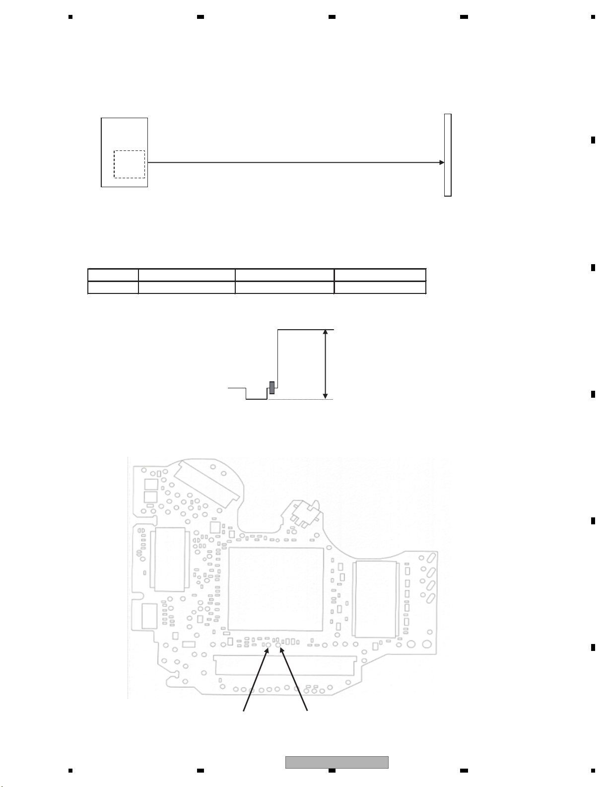
5 678
56
7
8
C
D
F
A
B
E
Check 11: Is the video circuit OK?
<Outline> Composite signal and component signal are output from DVD-LSI (IC1501), and are output from the
HOST I/F (CN1952) via a buffer circuit.
CN1952
HOST I/F
IC1501
DVD_LSI
Video
DAC
section
Composite COMPOSITE
Fig 11.1: Video circuit
<Checking method> Playback DVD-REF-A1 TITLE2 CHAPTER5 (WHITE 100%), and monitor COMPOSITE signal with
an oscilloscope with GNDV (stylus) being the reference. Set the trigger mode to “TV trigger” and
the trigger line to “150 line”.
No. Check point 1 (stylus) Specification value Reference waveform
1 COMPOSITE 1000 mVpp ± 5% Waveform 6
In case of NG, check the applicable line, the periphery of the major components in the drawing above, soldering of the
peripheral components and defective components.
PEAK
COMPOSITE signal Reference
value
Color burst
Pedestal level
BOTTOM
Horizontal sync signal
Side A
Fig 11.2: Waveform for the case of composite white 100% output
GNDV2
COMPOSITE
Fig 11.3: VIDEO signal check point
AVH-3400DVD/XUEW5
47
Page 48

1234
1234
C
D
F
A
B
E
Check 12:How to judge whether the flash memory has reached its life or not.
If the reaction to user operation is slow or operation is slow in general, there is a possibility that the flash memory
has reached its life.
Make judgment regarding the flash memory life by looking at the display of the LD power on time mode.
1. Let the LD energizing time displayed.
(Refer to the LD power on time mode for the method of displaying the LD energizing time.)
2. If the second digit from the left of the energizing time display is showing E,
such as “ E ”, it means that the flash memory has reached its life.
Example:
0E000BB8
48
AVH-3400DVD/XUEW5
Page 49
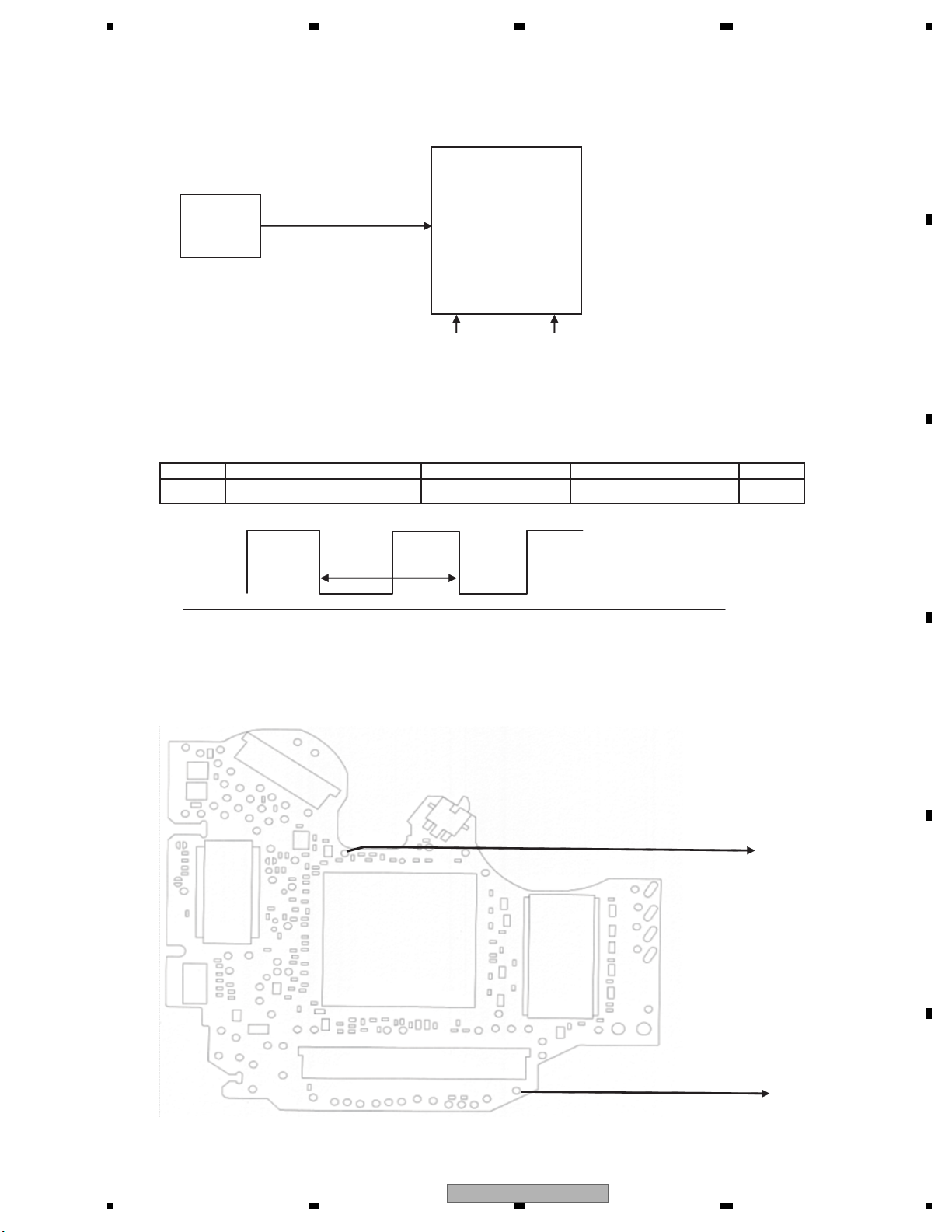
5 678
56
7
8
C
D
F
A
B
E
Check 13: 48 MHz Normal?
<Outline> CLOCK of a USB circuit is made using the 48 MHz master crystal oscillator (X1950).
IC1501
DVD-LSI
X1950
48MHz
crystal
Fig 13.1: Clock configuration
USB_CLOCK
VCC33 VCC12
<Check method> Turn the power on, and check with DGND1 being the reference.
In case of NG, check the applicable line, periphery of IC1501,
soldering of the peripheral components and defective components.
No. Check point Module No. Specification value Unit
2
IC1501 50pin - DGND1
Specification
value
ALL
48 MHz ± 200 ppm
ppm
GND
Side A
Fig 13.2: Clock specification value
48 MHz
Fig 13.3: 48 MHz check point
AVH-3400DVD/XUEW5
DGND1
49
Page 50
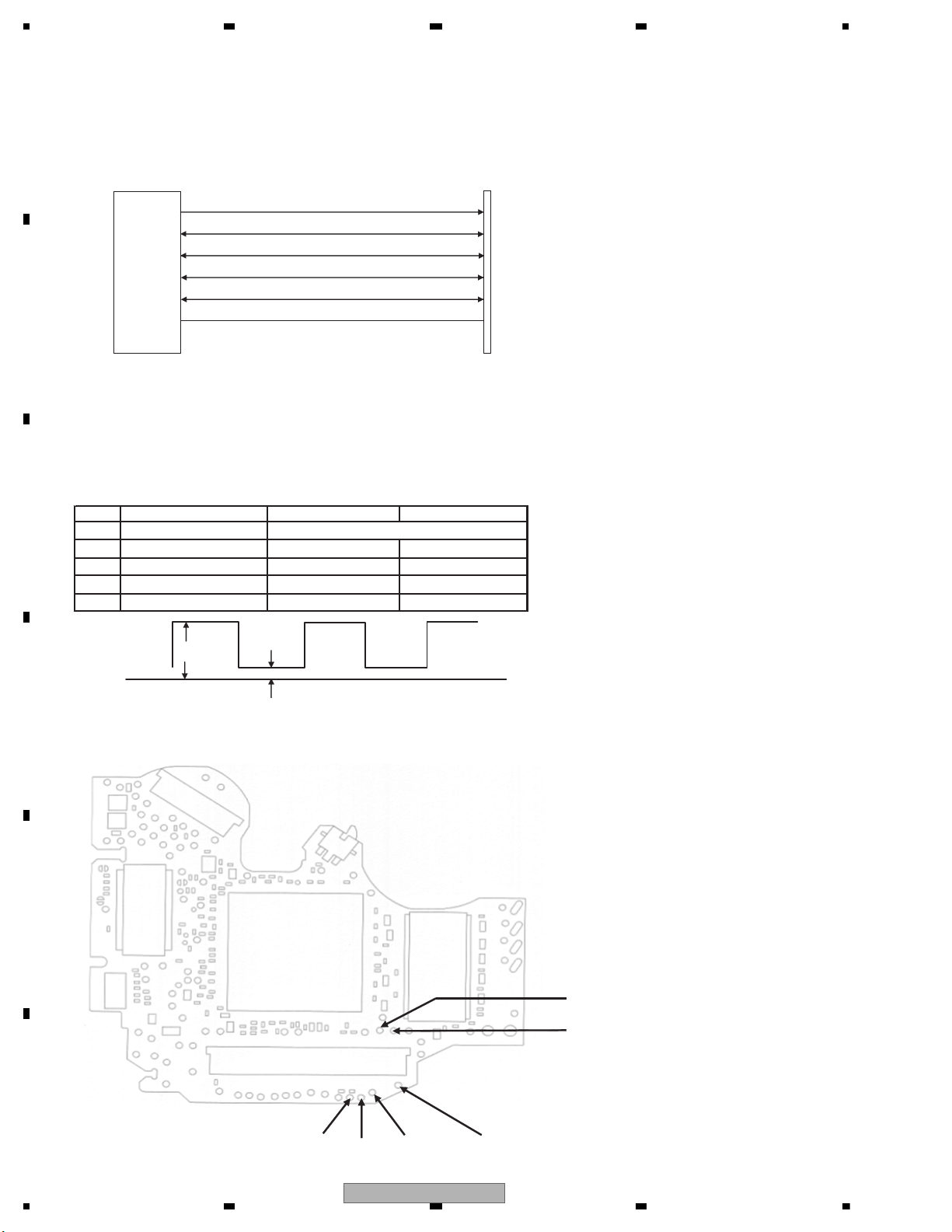
1234
1234
C
D
F
A
B
E
Check 14: Is USB Circuit OK?
<Outline>
The data is transmitted through D+, D- and SDA of HOST I/F while playing USB/IPOD.
USB memory uses only D+ and D-, but IPOD uses SDA (DATA) and SCL (CLOCK) in addition to D+ and D-.
CN1952
HOST I/F
Fig. 14-1: USB Circuit
<Check Method>
1. USB Memory: Play a song from USB memory and check D+ and D- with the DGND1 standards.
2. iPod: Connect iPod and check CP_RESET, SDATA and SCLOCK with the DGND1 standards until the Pioneer log
appears. When iPod Touch or iPhone is connected, the logo is not displayed but only a check mark is displayed.
Play a song from iPod and check D+/D- with the DGND1 standards.
When it does not conform to the standards, check appropriate line, main parts shown in the above figure,soldering of
peripheral parts and malfunctions in parts.
No. Checking spot (stylus) Standard value 2
1 CP_RESET
2
SDATA
VCC33*0.7 or more VCC33*0.2 or less
*Until the pioneer log appears after connecting the iPod
3 SCLOCK VCC33*0.7 or more VCC33*0.2 or less
*Until the pioneer log appears after connecting the iPod
4 D+ VCC33*0.7 or more VCC33*0.3 or less
5 D- VCC33*0.7 or more VCC33*0.3 or less
Fig.14.2: USB Circuit Communication Wave
Side A
VCC33*0.7 or more
IC1501
DVD-LSI
D-
D+
I2C_SCL
I2C_SDA
CP_RESET
Standard
value 1
Standard
value 2
DGND
SCLOCK
SDATA
D-
CP_RESET
D+
DGND1
Standard value 1
50
AVH-3400DVD/XUEW5
Page 51
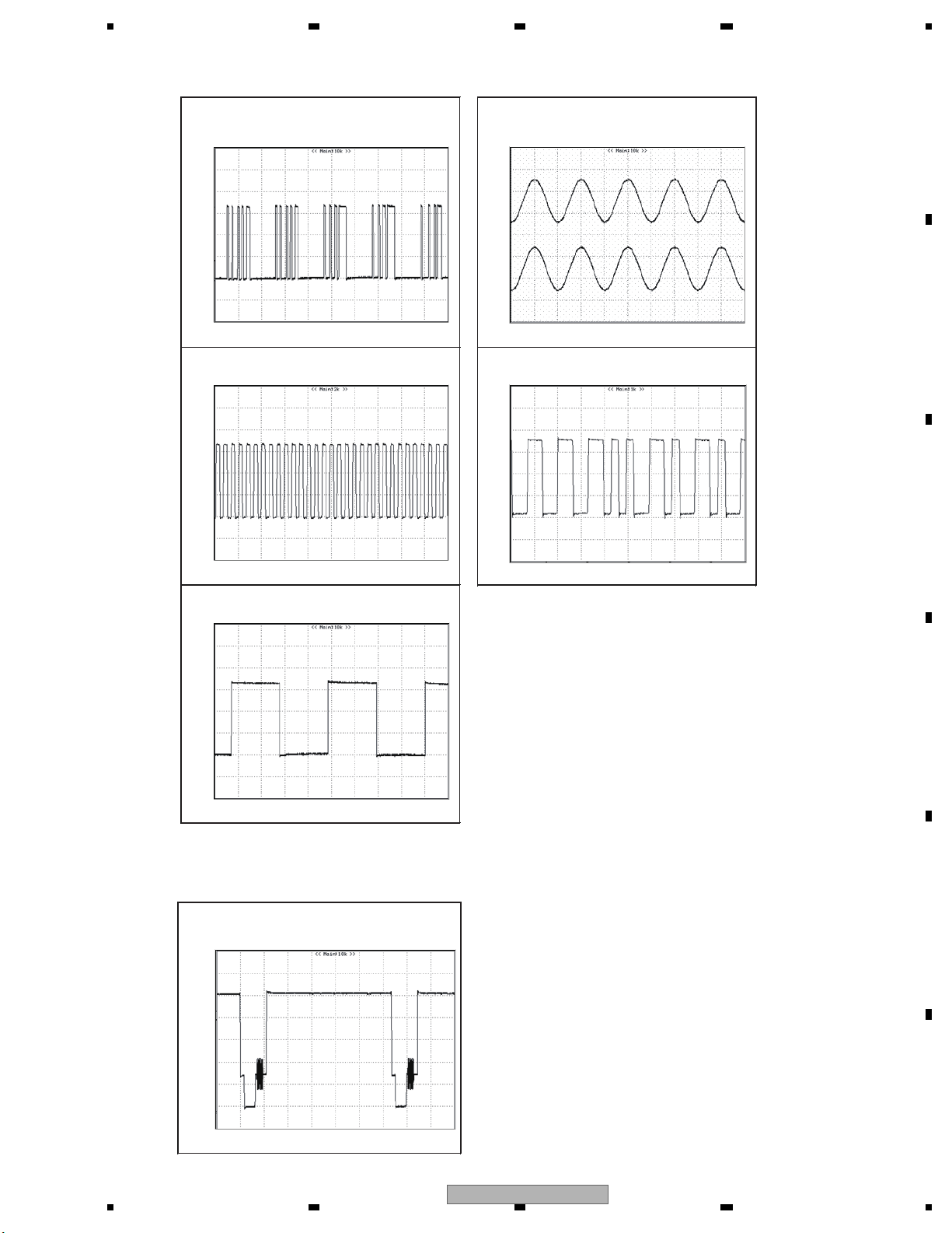
5 678
56
7
8
C
D
F
A
B
E
AUDIO
CH1 : LO
CH1 : ADOUT3
Reference voltage:DGND2 1 V/div. 5 μsec/div
CH2 : RO
Reference voltage:GNDAU2 2 V/div. 500 μsec/div
Gt
Gt
Waveform 1
CH1 : SRCK
Reference voltage:DGND2 1 V/div. 1 μsec/div
Gt
Waveform 2
CH1 : LRCK
Reference voltage:DGND2 1 V/div. 5 μsec/div
Gt
Waveform 4
CH1 : IECOUT
Reference voltage:DGND2 1 V/div. 500 nsec/div
Gt
Waveform 5
Gt
Waveform 3
VIDEO
[WHITE 100IRE]
CH1 : COMPO
Reference voltage:GNDV1 200 mV/div. 10 μsec/div
GNDV
Waveform 6
AVH-3400DVD/XUEW5
51
Page 52
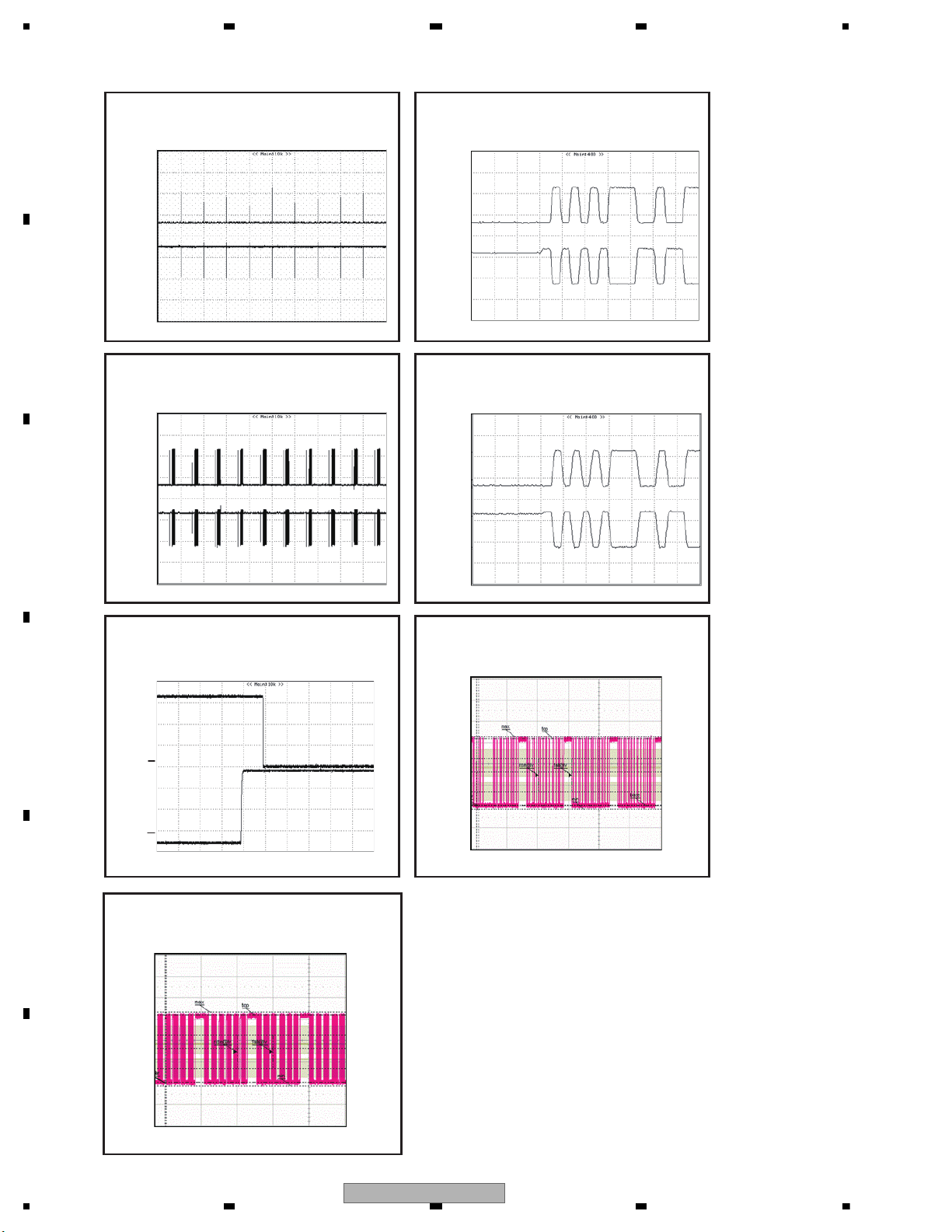
1234
1234
C
D
F
A
B
E
USB memory
USB memory
D+/D- communication waveform
D+/D- communication waveform
It checks with an oscilloscope.
It checks with an oscilloscope.
Reference voltage : DGND 1 ms/div 2 V/div
Reference voltage : DGND
200 ns/div 2 V/div
Waveform 7
Waveform 8
IPOD IPOD
D+/D- communication waveform D+/D- communication waveform
It checks with an oscilloscope. It checks with an oscilloscope.
Reference voltage : DGND
1 ms/div 2 V/div
Reference voltage : DGND 200 ns/div 2 V/div
Waveform 9
Waveform 10
IPOD
IPOD
IPOD
CP_RESET signal
SDA signal
SCL signal
A relation with NRES, At the time of RESET release
(It checks with an oscilloscope. )
It checks by LECORY.
It checks by LECORY.
Reference voltage : DGND
20 ms/div 1 V/div
Reference voltage : DGND 2 ms/div 1 V/div
Reference voltage : DGND 500 μs/div 1 V/div
Waveform 11
Waveform 12
Waveform 13
DGND
D-
D+
DGND
D+
DGND
DGND
D-
D+
DGND
DGND
D-
DGND
DGND
D-
D+
CP_RESET
DGND
NRES
DGND
DGND
SDA
SCL
DGND
USB, IPOD
52
AVH-3400DVD/XUEW5
Page 53
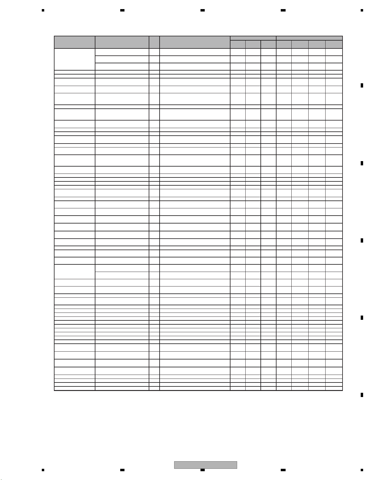
5 678
56
7
8
C
D
F
A
B
E
Error status
OSD *1
UART
*2
Meaning
Disc
USB
(MSC)
USB
(iPod)
ACC
Off/On
Source
Off/On
Eject/
With no device
Play Key
Media Error
UNPLAYABLE DISC
00h
A disc containing the unplayable format only
X- -XX X -
INCOMPATIBLE DEVICE
00h
USB device that doesn't correspond
-XXXX X -
UNPLAYABLE FILE
00h
USB device of format alone that cannot be reproduced
-X-X X X -
Open
(No display)
10h
Door open error
X
--* * * *
Read Error
ERROR-02-99
20h
Transfer start error
X
--
XXXX
Focus Error(Focus Error in
mechanism set up)
ERROR-02-90
21h
Focus error
X--XXXX
Surface Error
ERROR-02-9E
22h
Focus error during set up
(A focus has never been achieved with that disc.)
X- - - - X -
Address not found
(Invalid Track)
ERROR-02-80
23h
Address not found.
X--XXXX
Spindle Lock
ERROR-02-91
24h
Spindle lock NG(the disc cannot rotate)
X
--
XXXX
Carriage HOME
ERROR-02-92
25h
Carriage home NG
(The pick up tries to return to carriage home,
but it cannot go back and stopped.)
X--XXXX
ID/SUBCODE Read Error
ERROR-02-94 26h
ID/SUBCODE Read Error (ID/SUBCODE cannot
be read due to scratch or stain.)
X--XXXX
AV CHIP decode Error
ERROR-02-9A
2Ah
AV CHIP decode NG(AV chip cannot be decoded.)
X
X
X
XXXX
AV CHIP Recovery NG
ERROR-02-9B
2Bh
AV CHIP recovery NG
X
X
-
XXXX
Error of PLAY BACK
Mode Status
ERROR-02-9C
2Ch
Playback state error
(An error due to software bug.)
XX-XXXX
Disc Data Error
ERROR-02-9D
2Dh
Disc Data NG
X
-
-
XXXX
Temp Error(In Case of
High Temperature)
THERMAL PROTECTION IN MOTION
30h
High temperature(Playback is stopped because the pick
up temperature is 89 C or higher.)
X--X---
No Disc
(including Disc loading
and ejecting)
(No display)
40h
Disc has not been inserted.
(Including Load in process or Eject in process.)
X- - * * * *
Loading_Mecha Error
(No display)
50h
Loading mechanism error
(The disc cannot be clamped.)
X X *11 X *11 X - X *12 -
Communication fault attesting iPod
ERROR-02-60
60h
Communication fault attesting iPod
X *13
-
XX
-
X *14
-
iPod authentication data is abnormal
ERROR-02-61
61h
iPod authentication data is abnormal
X *13
-
XX
-
X *14
-
iPod attestation retrying failure
ERROR-02-62
62h
iPod attestation retrying failure
X *13
-
XX
-
X *14
-
iPod attestation time out
ERROR-02-63
63h
iPod attestation time out
X *13
-
XX
-
X *14
Error when iPod is connected/
It is generated STALL by the USB
communication
ERROR-02-64
64h
Error when iPod is connected/
It is generated STALL by the USB communication
--XX - X -
Error setting iPod
ERROR-02-65
65h
Error setting iPod
--
XX
-
X
-
Demand timeout when
initial is communicated
ERROR-02-66
66h
Demand timeout when
initial is communicated
--XX - X -
Protocol version
non-correspondence
ERROR-02-67
67h
Protocol version non-correspondence
(It is necessary to Version Up the iPod by iTunes.)
--XX - X -
Timeout when protocol
version is judged
ERROR-02-68
68h
Timeout when protocol
version is judged
--XX - X -
No songs error
(No display)
69h
iPod does not have music.
(It is necessary to put music into iPod by iTunes)
--XX - X -
iPod control forwarding/
Intarapta forwarding error
ERROR-02-6A
6Ah
iPod control forwarding / Intarapta forwarding error
--XX - X -
Demand timeout
iPod's reproducing
ERROR-02-6B
6Bh
Demand timeout iPod's reproducing
--XX - X -
Remote switch error
ERROR-02-6C
6Ch
Remote switch error
--
XX
-
X
Remote switch demand
timeout
ERROR-02-6D
6Dh
Remote switch demand timeout
--XX - X -
Demand timeout to an
iPodApl(Pandora)
ERROR-02-6E
6Eh
Demand timeout to an iPodApl(Pandora)
--XX - X -
DRM Error
PROTECTED DISC
70h
DRM error (All music cannot be played back due
to DRM.)
X- -XX X -
NO ACCESSIBLE DATA AVAILABLE
70h
-X-X X X -
Region code Error
DIFFERENT REGION DISC
90h
Region code NG (Unable to be played back due
to incorrect mechanism region.)
X- -XX X -
CPRM*7 Key Error *8
UNPLAYABLE DISC
93h
Key Error for playback
X- -X - X -
REQUEST Error
ERROR-02-A0 A0h
REQUEST_error
X
--
XXXX
Failure in issuing read
command (chip dependent)
ERROR-02-A1 A1h
Failure in issuing the read command
X--XXXX
Adjustment of L0 is NG.
ERROR-02-A2 A2h
L0 adjustment is NG.
X
--
XXXX
Adjustment of L1 is NG.
ERROR-02-A3 A3h
L1 adjustment is NG.
X
--
XXXX
LD system NG
ERROR-02-A4 A4h
LD system NG
X
--
XXXX
Gain adjustment system NG.
ERROR-02-A5 A5h
Gain adjustment system NG.
X
--
XXXX
Gain determining system NG.
ERROR-02-A6 A6h
Gain determining system NG.
X
--
XXXX
Servo initial setting related items NG.
ERROR-02-A7 A7h
Servo initial setting related items NG.
X
--
XXXX
Disc is not clamped yet.
ERROR-02-A8
A8h
Disc is not clamped yet.
X
-
-
XXXX
Tracking system NG.
ERROR-02-A9
A9h
Tracking system NG
X
-
-
XXXX
Media setting system NG.
ERROR-02-AA
AAh
Media setting system NG
X
-
-
XXXX
Focus Error
ERROR-02-AB ABh
JUMP over layers NG
X
-
-
XXXX
Error of PLAY BACK
Mode Status
ERROR-02-B0
B0h
Navigation command error
X--XXXX
Error of PLAY BACK
Mode Status
ERROR-02-B1
B1h
Retry over
X--XXXX
DivX DRM Inofrmation
Update Error *10
ERROR-02-C1
C1h
DivX DRM inofrmation update error
X- -X -
--
Error when MCS is connected/
It is generated STALL by the USB
communication
ERROR-02-D0
D0h
Error when MCS is connected / It is generated
STALL by the USB communication
-X- - - X -
CBW and CSW forwarding error
ERROR-02-D1
D1h
CBW and CSW forwarding error
-
X
-- -
X
-
Audio class band securing failure
ERROR-02-D8
D8h
Audio class band securing failure
-
-
XX
-
X
-
Audio class FS setting failure
ERROR-02-D9
D9h
Audio class FS setting failure
-
-
XX
-
X
-
Undefined Error
ERROR-FF-FF FFh
Undefined error
X
--
XXXX
Method of resetGeneration source
DRM error (All music cannot be played back due
to DRM.)
X : Cancel the error by operation. - : Error is not cancelled by operation. * : No setting
*1 A content displayed on OSD. As for the items having multiple display patterns, the upper row is for the Japanese version Full GUI, and the lower
row is for the Touch Panel model and Full GUI (English version).
*2 A parameter of UART command, such as “receipt error notice”, that the DVD mechanism transmits.
*7 CPRM(Content Protection for Recordable Media) : A copyright protection technique for digital contents used for re-writable DVD or memory card.
*8 DVD-VR model only.
*10 This occurs when the DRM information update notice is sent from the DVD mecha but no DRM information update response is returned.
*11 Although it is USB source, it notifies as an error of DISC source.
*12 Although it is USB source, iIt cancels only by Disc eject.
*13 Although it is DISC source, it notifies as an error of USB source.
*14 Although it is DISC source, It cancels only without Device.
5.4 ERROR CODE LIST
AVH-3400DVD/XUEW5
53
Page 54

1234
1234
C
D
F
A
B
E
External storage device (USB)
Message Cause Action
Unplayable
File
This type of file
cannot be played
on this unit.
Select a file that
can be played.
There are no
songs.
Transfer the audio
files to the USB
portable audio
player/USB memory and connect.
Security for the
connected USB
memory is enabled.
Follow the USB
memory instructions to disable security.
Format Read Sometimes there
is a delay between the start of
playback and
when you start to
hear any sound.
Wait until the message disappears
and you hear
sound.
Skipped The connected
USB portable
audio player/
USB memory
contains WMA
files that are protected by
Windows Media™DRM 9/10.
Play an audio file
not embedded with
Windows Media
DRM 9/10.
Message Cause Action
Protect All the files on
the connected
USB portable
audio player/
USB memory are
protected by
Windows Media
DRM 9/10.
Transfer audio files
not protected by
Windows Media
DRM 9/10 to the
USB portable
audio player/USB
memory and connect.
Incompatible
USB
The USB device
connected to is
not supported by
this unit.
Connect a USB
portable audio
player or USB
memory that is
USB Mass Storage
Class compliant.
The USB device
is not formatted
with FAT16 or
FAT32.
The connected
USB device should
be formatted with
FAT16 or FAT32.
Check USB The USB connec-
tor or USB cable
has shortcircuited.
Check that the
USB connector or
USB cable is not
caught in something or damaged.
The connected
USB portable
audio player/
USB memory
consumes more
than maximum
allowable current.
Disconnect the
USB portable
audio player/USB
memory and do
not use it. Turn the
ignition switch to
OFF, then to ACC
or ON and then
connect a compliant USB portable
audio player/USB
memory.
Error-02-9X/-DXCommunication
failed.
Perform one of the
following operations.
–Turn the ignition
switch OFF and
back ON.
–Disconnect the
USB portable
audio player/USB
memory.
–Change to a different source.
Then, return to the
USB portable
audio player/USB
memory.
54
AVH-3400DVD/XUEW5
Page 55
5 678
56
7
8
C
D
F
A
B
E
Message Cause Action
Rental expired.
The inserted external storage device contains
expired DivX
VOD content.
Select a file that
can be played.
Video resolution not supported
The inserted external storage device contains a
high definition
DivX/MPEG-1/
MPEG-2/MPEG-4
file.
Select a file that
can be played.
It is not possible to write it
in the flash.
This unit’s flash
memory used as
the temporary
storage area is
full.
Select a file that
can be played.
Your device is
not authorized to play
this DivX protected video.
This unit’s DivX
registration code
has not been
authorized by the
DivX VOD contents provider.
Register this unit
to the DivX VOD
contents provider.
Format Read Sometimes there
is a delay between the start of
playback and
when you start to
hear any sound.
Wait until the message disappears
and you hear
sound.
Video frame
rate not supported
DivX file’s frame
rate is more than
30 fps.
Select a file that
can be played.
Audio Format
not supported
This type of file is
not supported on
this unit.
Select a file that
can be played.
iPod
Message Cause Action
Format Read Sometimes there
is a delay between the start of
playback and
when you start to
hear any sound.
Wait until the message disappears
and you hear
sound.
Message Cause Action
Error-02-6X/9X/-DX
Communication
failed.
Disconnect the
cable from the
iPod. Once the
iPod’s main menu
is displayed, reconnect the iPod and
reset it.
iPod failure. Disconnect the
cable from the
iPod. Once the
iPod’s main menu
is displayed, reconnect the iPod and
reset it.
Error-02-67 The iPod firm-
ware version is
old.
Update the iPod
version.
Stop There are no
songs.
Transfer songs to
the iPod.
There are no
songs in the current list.
Select a list that
contains songs.
Not Found No related
songs.
Transfer songs to
the iPod.
AVH-3400DVD/XUEW5
55
Page 56
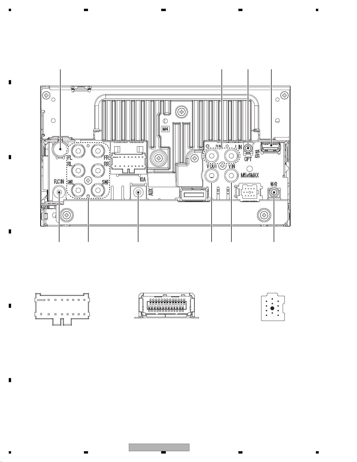
1234
1234
C
D
F
A
B
E
5.5 CONNECTOR FUNCTION DESCRIPTION
AUDIO
INPUT
ANTENNA IN
OPTICAL
OUTPUT
USB IF
VIDEO
INPUT
REAR
MONITOR
VIDEO
OUTPUT
FRONT
REAR
SUBWOOFER
PRE-OUT
11
10
9
8
7
6
5
4
3
2
1
IP-BUS INPUT
(Except
AVH-3400DVD
/XUEW5)
(Except
AVH-3400DVD/XUEW5)
1. BUS+
2. BUSG
3. BUSLG
4. NC
5. BUS-
6. BUSRG
7. BUSL+
8. ASENBO
9. BUSR+
10. BUSR-
11. BUSL-
REARVIEW
CAMERA IN
AUX INPUT WIRED REMOTE
CONTROL
NAVI INTERFACE
1
2
25
26
1. FR-
2. RR-
3. FR+
4. RR+
5. FL-
6. RL-
7. FL+
8. RL+
13579111315
246810121416
9. P. BRAKE
10. MUTE
11. B.REM
12. ILM
13. BGSENS
14. ACC
15. GND
16. B.UP
POWER SUPPLY
1 : ANR
2 : ANG
3 : ANB
4 : CSYNC
5 : GNDSIG
6 : NC
7 : NC
8 : NC
9 : ASENBO
10 : NC
11 : NC
12 : NC
13 : ONSEI+
14 : ONSEI 15 : NC
16 : NC
17 : NC
18 : NC
19 : GNDD
20 : TVON
21 : GUIDE ON
22 : NC
23 : NC
24 : SYS_TO_NAVI
25 : NAVI_TO SYS
26 : GNDD
A
A
B
B
C
C
56
AVH-3400DVD/XUEW5
Page 57
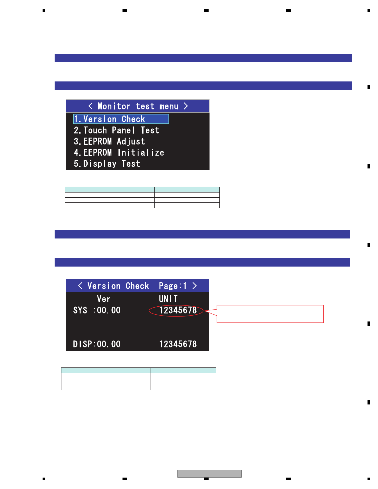
5 678
56
7
8
C
D
F
A
B
E
[Method for Mode IN]
Turn on BUP and ACC while pressing REVERSE and EJECT.
Use Remote Control with 10 keys for other AVH models.
[Display specifications]
[Method for Mode IN]
Choose "Version Check" among the monitor test mode menu screen.
[Display specifications]
[Operation specification]
Operational description Remote controller key
Selection cursor up movement 2
Selection cursor down movement 8
Menu enter 5
1. Version Check
[Operation specification]
Operational description Remote controller key
Return to test mode mene 1
Page up
9
Page down
7
When 8 digits of read number is strange,
displayed with red.
6. SERVICE MODE
6.1 MONITOR TEST MODE
AVH-3400DVD/XUEW5
57
Page 58
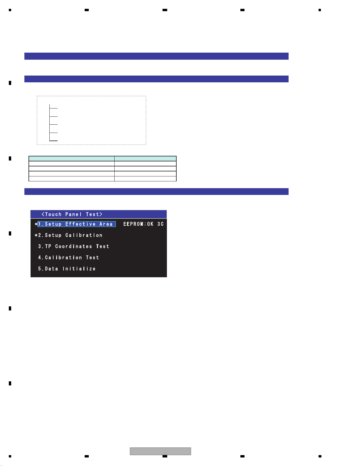
1234
1234
C
D
F
A
B
E
[How to activate the touch panel test mode]
Choose "Touch Panel Test" among the monitor test mode menu screen.
[Menu types in the mode]
The calibration test mode consists of the following menus.
Top menu
[Description of the top menu]
[Display specification]
Conditions for lighting of the adjustment complete mark “ * ”.
Outermost circumference inspection :
In case the outermost circumference inspection has been completed normally.
Calibration inspection :
In case the calibration has been completed normally.
Conditions for the adjustment complete mark “ * ” to go out.
Outermost circumference inspection :
In case the outermost circumference inspection has never been performed.
In case the EEPROM initialization has been performed.
In case the adjustment value has been initialized.
Calibration inspection :
In case the calibration inspection has never been performed.
In case the EEPROM initialization has been performed.
In case the adjustment value has been initialized.
Data initialization
Outermost circumference inspection
Calibration inspection
Coordinate inspection
Calibration verification
[Operation specification]
Operational description Remote controller key
Selection cursor up movement 2
Selection cursor down movement 8
Return to test mode mene 1
Menu enter 5
2. Touch Panel Test
58
AVH-3400DVD/XUEW5
Page 59
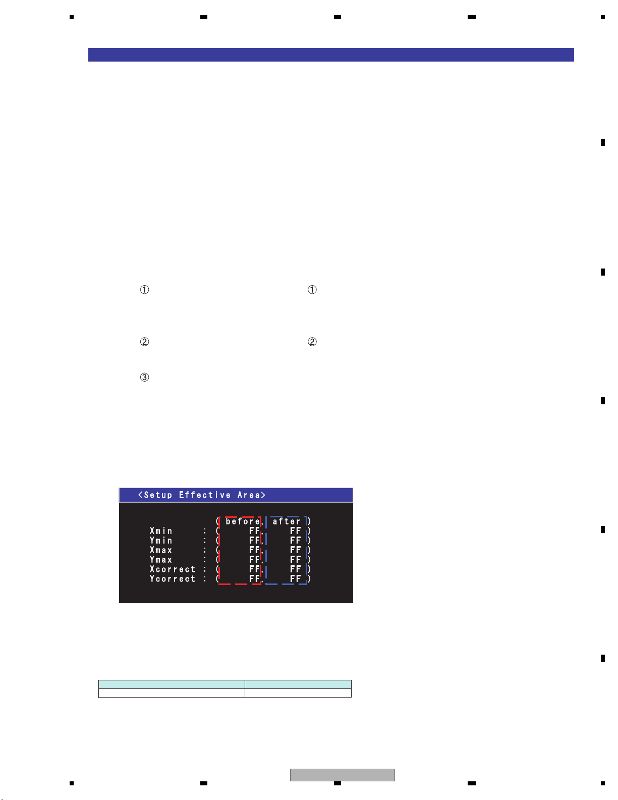
5 678
56
7
8
C
D
F
A
B
E
[Outermost circumference inspection]
[Outline]
Outermost circumference value of X and Y is obtained by tracing the outermost circumference of
the touch panel screen.
When exiting the menu screen by pressing 5 key, the captured value is stored in the EEPROM.
Furthermore, when storing the value, checking is made as to whether the value is within the range or not.
When the value is within the range.
Write the following value and adjustment information to the EEPROM, then “OK” is displayed.
1. The outermost value of X and Y(min/max) : 4 byte
2. The reference value for A/D correction of X,Y : 2 byte
3. Adjustment information(Adjustment OK) : 1 byte
When the value is within the range.
Write the following adjustment information to the EEPROM, then “NG” is displayed.
1. Adjustment information(Adjustment NG) : 1 byte
The initial value and the setting value allowable range are as follows.
<Before initial value> <After initial value>
Outermost value Outermost value
Xmin : 39h Xmin : 78h
Ymin : 3Eh Ymin : 78h
Xmax : F7h Xmax : B4h
Ymax : EFh Ymax : B4h
A/D correction value A/D correction value
X : 33h X : 00h
Y : 38h Y : 00h
Setting value allowable range
X direction Minimum value : 00h to 80h
Maximum value : 9Eh to FFh
Maximum value - Minimum value : more then 73h
Y direction Minimum value : 00h to 83h
Maximum value : 9Ah to FFh
Maximum value - Minimum value : more then 6Bh
[Display specifications]
Outermost circumference inspection in process
X/Y information of [MIN] and [MAX] of the outermost circumference are displayed.
[BEFOR] indicates the value stored in the EEPROM.
[AFTER] indicates MIN/MAX of the A/D value currently captured.
[Operation specification]
Operational description Remote controller key
Return to top mene 5
AVH-3400DVD/XUEW5
59
Page 60
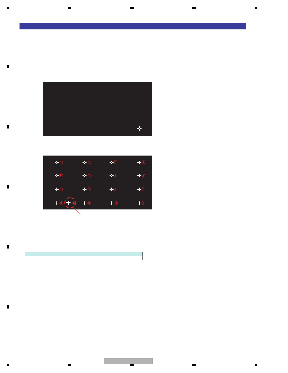
1234
1234
C
D
F
A
B
E
[16 points adjustment]
[Outline]
When correctly touched, the cursor will disappear, and the next cursor will appear. Calibration is conducted
by repeating this process 16 times.
When the 17th point has been finally touched, setting information for the 16 points and the normal ending
information, total of 17 byte data, are written into the EEPROM, and the screen returns to the TOP menu.
[Display specifications]
16 points adjustment in process
Order of display of the locations to be pressed.
This point is intended to end the
calibration inspection, and therefore, the
corrected value of this point is not obtained.
[Operation specification]
Operational description Remote controller key
Return to top mene 5
60
AVH-3400DVD/XUEW5
Page 61
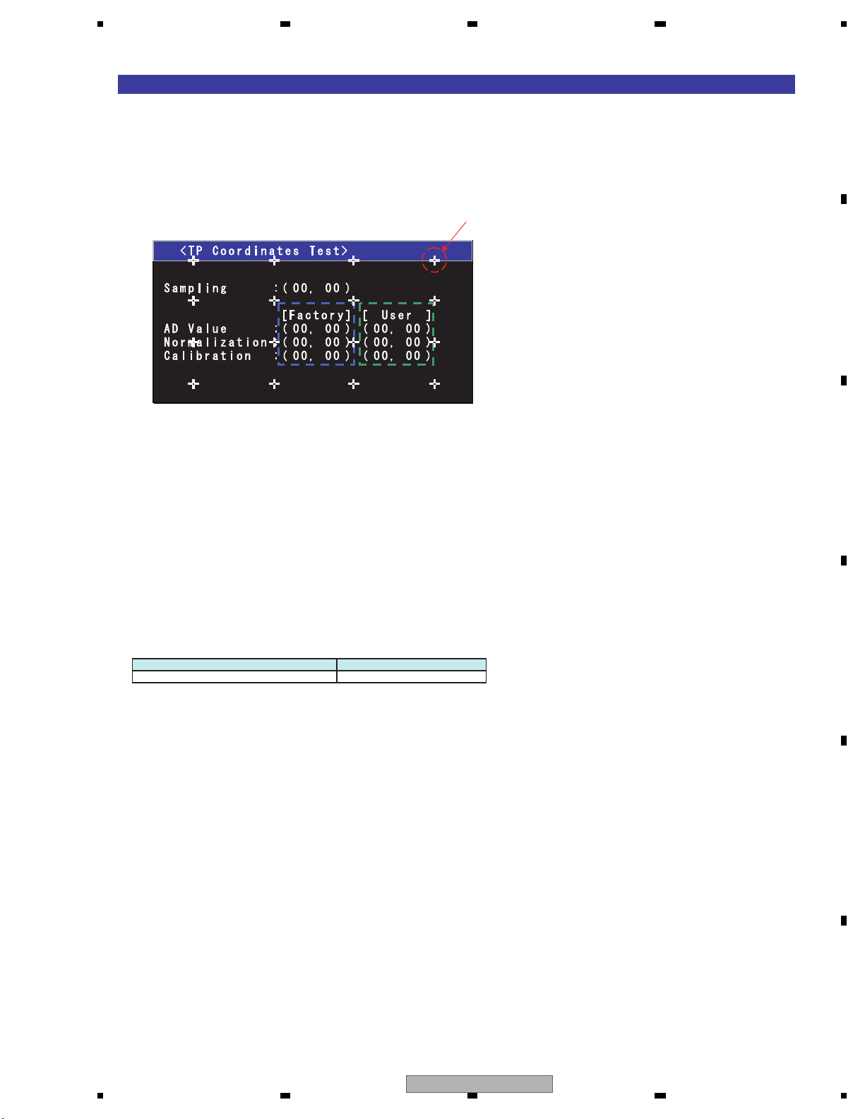
5 678
56
7
8
C
D
F
A
B
E
[Coordinate inspection]
[Outline]
The coordinate before correction and after correction at the time of pressing the touch panel are displayed for
coordinate verification.
Furthermore, the red "+" cursor can be moved by the key operaiont mentioned bellow, and the coordinate of
the cursor center is displayed.
[Display specifications]
Fixed display
[Operation specification]
Operational description Remote controller key
Return to top mene 1
Each displayed coordinate is as follows.
The values under [Factory] are the corrected values in the Factory region and the values under [User] are
the corrected values in the User region.
• Sampling : A/D value (X direction, Y direction) of the pressed point is displayed.
• AD Value : The coordinate (X direction, Y direction) of the A/D value of the pressed point corrected by
the reference value for A/D correction is displayed.
• Normalization : The coordinate (X direction, Y direction) after normalizing the A/D corrected coordinate
within the effective range is displayed. (0~255)
• Calibration : The coordinate (X direction, Y direction) which is the result of adding the correction
by calibration to the normalized coordinate is displayed.
16 calibration points "+" are displayed in white.
AVH-3400DVD/XUEW5
61
Page 62
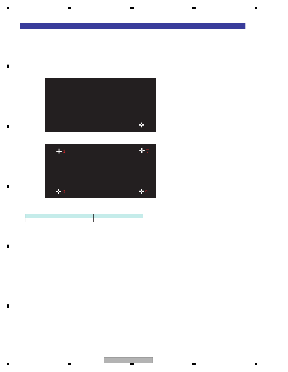
1234
1234
C
D
F
A
B
E
[Calibration verification]
[Outline]
Touch the cursor “+” displayed on the screen. The correct touch will delete the cursor and another cursor
will be displayed. The incorrect touch will make the characters of cursor turn red.
Repeat this for 4 points, and “OK” is displayed upon the last press of 4th point.
[Display specifications]
The pushing order
confirming
[Operation specification]
Operational description Remote controller key
Return to top mene 1
62
AVH-3400DVD/XUEW5
Page 63
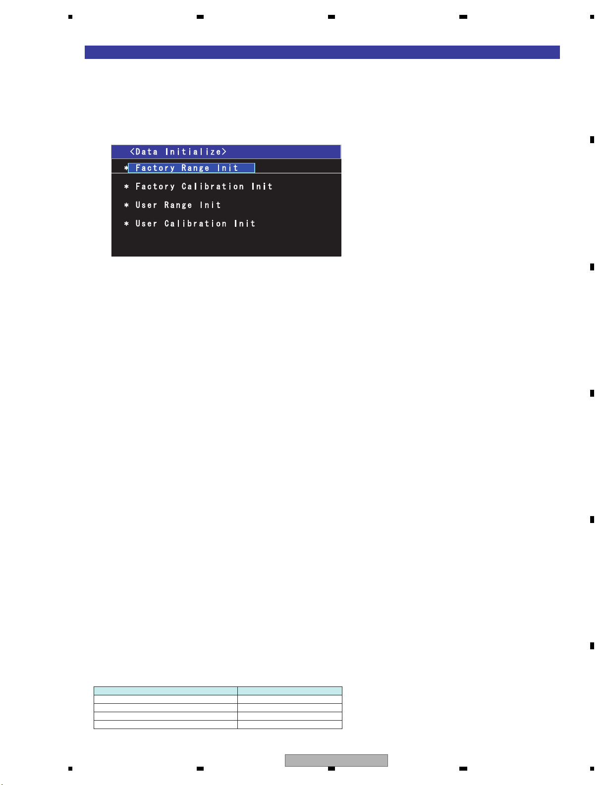
5 678
56
7
8
C
D
F
A
B
E
[Data initialization]
[Outline]
Result of outermost circumference inspection and of calibration inspection (corrected value) are returned to
their initial values.
As for the initialized items, the initial values are written into the EEPROM and the adjustment information
is cleared.
[Display specifications]
Conditions for the adjustment completion mark (*) to be lighted up.
Outermost circumference inspection
When the outermost circumference inspection of the calibration for line has been completed normally.
Calibration inspection
When the calibration inspection of the calibration for line has been completed normally.
User outermost circumference inspection
When the user outermost circumference inspection of the calibration for line has been completed normally.
User calibration inspection
When the user calibration inspection of the calibration for line has been completed normally.
Conditions for the adjustment completion mark (*) to go out.
Outermost circumference inspection
When the above mentioned lighting conditions are not applicable.
When the adjusted value has been initialized (Data initialize).
When the EEPROM has been initialized.
Calibration inspection
When the above mentioned lighting conditions are not applicable.
When the adjusted value has been initialized (Data initialize).
When the EEPROM has been initialized.
User outermost circumference inspection
When the above mentioned lighting conditions are not applicable.
In case the outermost circumference inspection of the calibration for line or the 16-point adjustment is normally
terminated after normal termination of the outermost circumference inspection for user calibration.
When the adjusted value has been initialized (Data initialize).
When the EEPROM has been initialized.
User calibration inspection
When the above mentioned lighting conditions are not applicable.
In case the outermost circumference inspection of the calibration for line or the 16-point adjustment is normally
terminated after normal termination of the outermost circumference inspection for user calibration.
When the adjusted value has been initialized (Data initialize).
When the EEPROM has been initialized.
[Operation specification]
Operational description Remote controller key
Selection cursor up movement 2
Selection cursor down movement 8
Menu enter 5
Return to test mode mene 1
AVH-3400DVD/XUEW5
63
Page 64
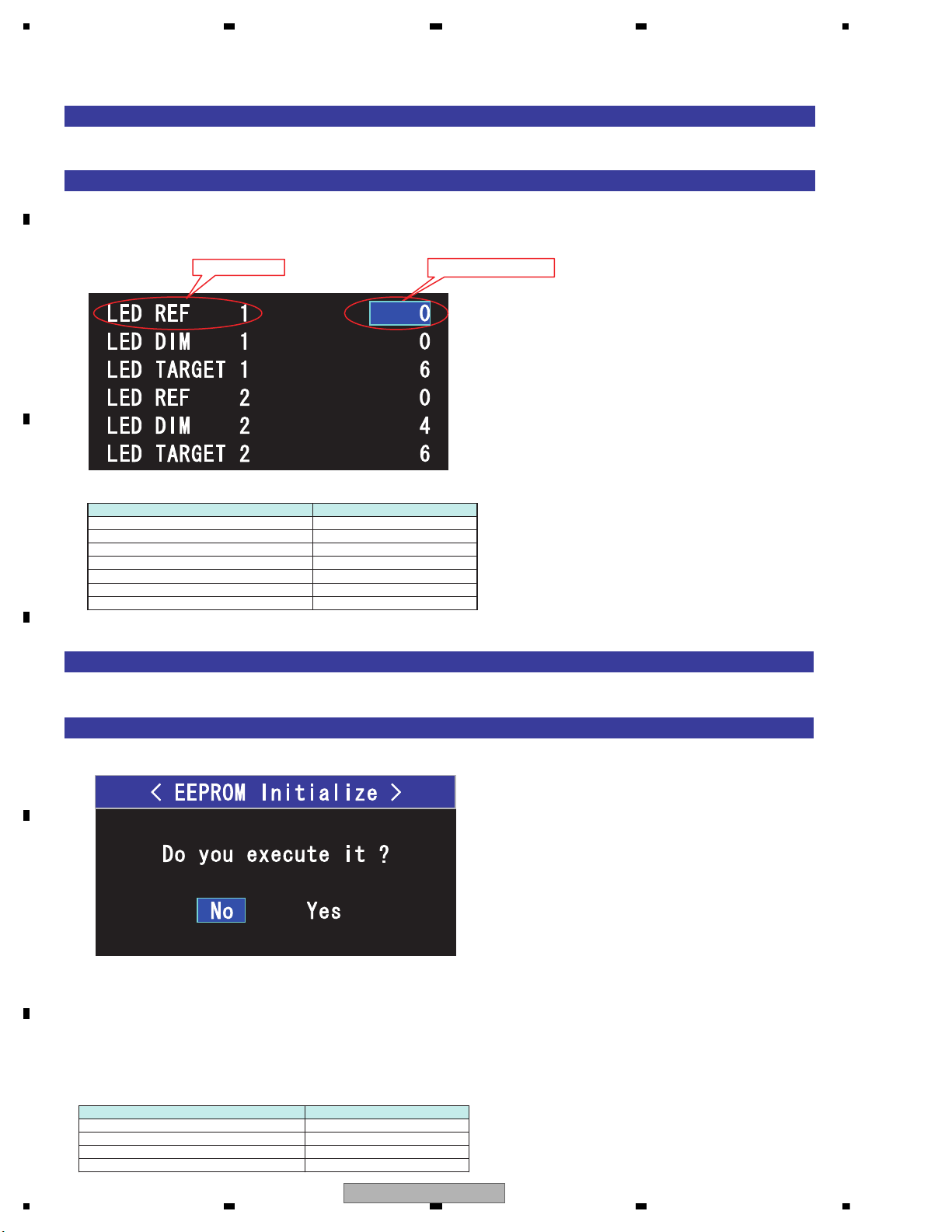
1234
1234
C
D
F
A
B
E
[Method for Mode IN]
Choose "EEPROM Adjust" among the monitor test mode menu screen.
[Display specifications]
3. EEPROM Adjust
example)
Adjustment value
Setting item
[Operation specification]
Operational description Remote controller key
Selection cursor up movement 2
Selection cursor down movement 8
Item content value up 6
Item content value down 4
Next menu page 9
Former menu page 7
Return to test mode mene 1
[Method for Mode IN]
Choose "EEPROM Initialize" among the monitor test mode menu screen.
[Display specifications]
Default of a cursor is the location of "No".
Choose "YES" and decide, initialize a setting value.
*) Don't turn off power while initializing.
When normally ends, "success" is displayed.
When will not end in four seconds, judged to be abnormal, "failure" is displayed.
[Operation specification]
Operational description Remote controller key
Selection cursor left movement 4
Selection cursor right movement 6
Return to test mode mene 1
Menu enter 5
4. EEPROM Initialize
The setting items and the adjusted values are displayed on each page.
*The adjusted value section indicates initial values stored in EEPROM.
*If writing a value fails, the indication will not change.
64
AVH-3400DVD/XUEW5
Page 65
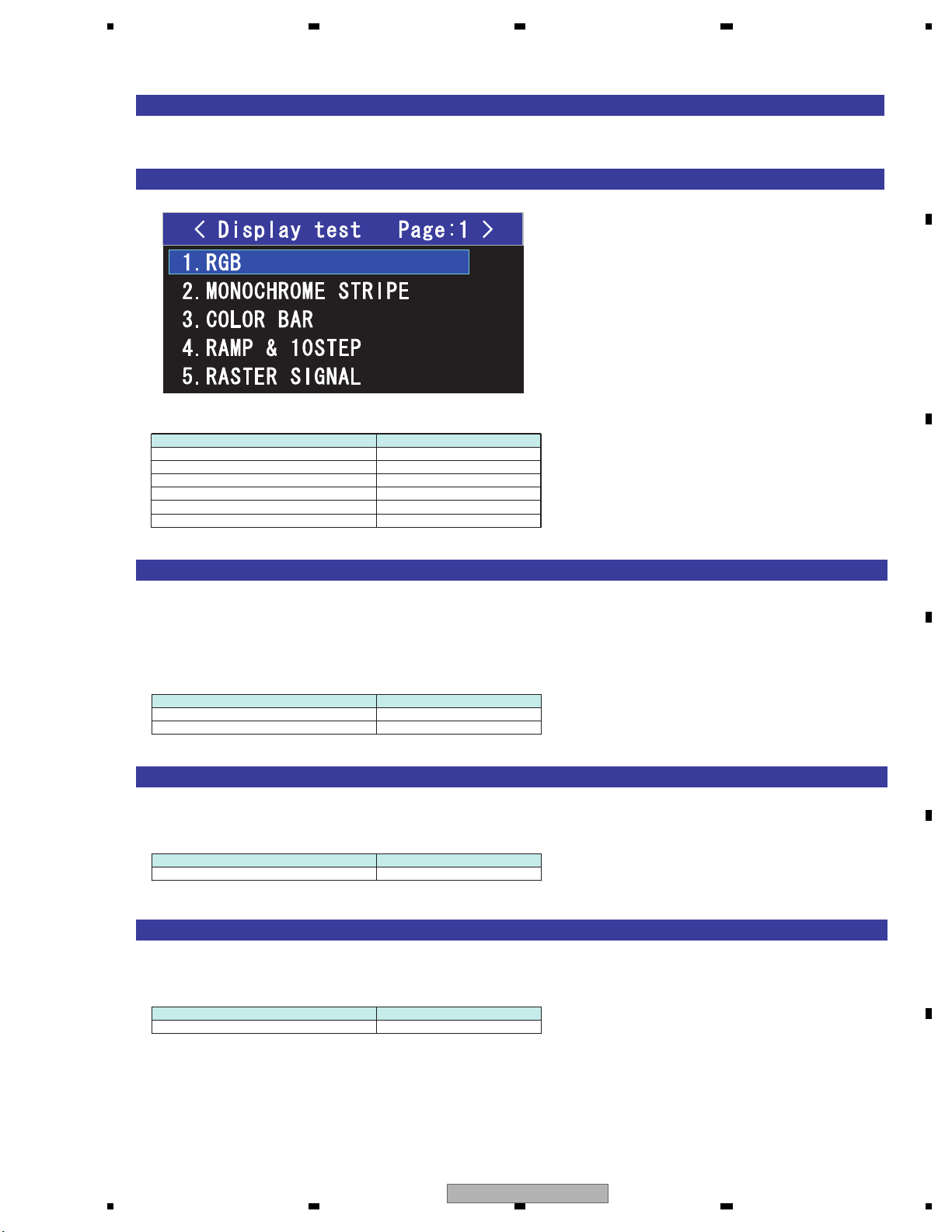
5 678
56
7
8
C
D
F
A
B
E
[Method for Mode IN]
Choose "Display Test" among the monitor test mode menu screen.
[Display specifications]
5. Display Test
[Operation specification]
Operational description Remote controller key
Selection cursor up movement 2
Selection cursor down movement 8
Page up 9
Page down 7
Menu enter 5
Return to test mode mene 1
[RGB]
RGB is plotted in the following pattern:
R100% -> R50% -> G100% -> G50% -> B100% -> B50% -> BLACK -> GRAY -> WHITE -> GREEN and MAGENTA
dot signal
(The display of the screen will be changed in 1 second.)
[Operation specification]
Operational description Remote controller key
Stop/Restart 5
Return to test mode mene 1
[MONOCHROME STRIPE]
Display of monochrome stripe signal (1dot Width)
[Operation specification]
Operational description Remote controller key
Return to test mode mene 1
[COLOR BAR]
Display of color bar signal
[Operation specification]
Operational description Remote controller key
Return to test mode mene 1
AVH-3400DVD/XUEW5
65
Page 66
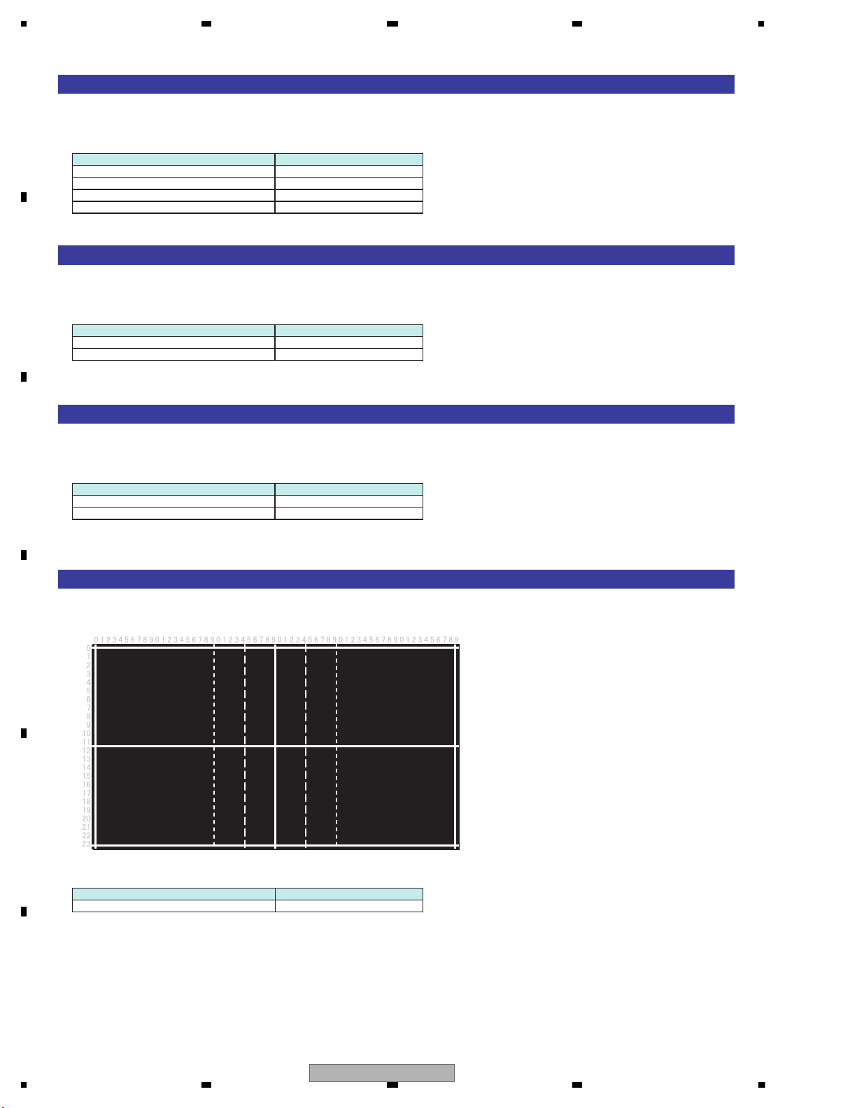
1234
1234
C
D
F
A
B
E
[RAMP & 10STEP]
Display of step signal and signal for alpha blend check
[Operation specification]
Operational description Remote controller key
alpha blend rate up 2
alpha blend rate down 8
Next signal 5
Return to test mode mene 1
[RASTER SIGNAL]
Display of signal for step confirmation
[Operation specification]
Operational description Remote controller key
Next signal 5
Return to test mode mene 1
[CONTRAST]
Display of Black/White signal
[Operation specification]
Operational description Remote controller key
Next signal 5
Return to test mode mene 1
[CENTER MARKER]
Display of signal for screen central location setting.
[Operation specification]
Operational description Remote controller key
Return to test mode mene 1
66
AVH-3400DVD/XUEW5
Page 67
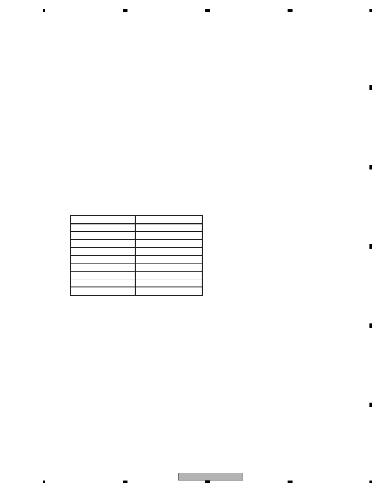
5 678
56
7
8
C
D
F
A
B
E
The service test mode is used to check functions in fault diagnosis by a serviceman in case of any defect found in the
DVD mecha.
This mode is enabled only when the test mode is activated. At this time, no normal operation is executed.
1. Outline
The service test mode is used to check functions in fault diagnosis by a serviceman in case of any defect found in the
DVD mecha. No general user goes into this mode.
The mode is implemented mainly to check the FE part. It is originally the test mode at the FE part implemented in the
PC communication, which is modified to allow implementation in the HOST communication.
The command for the test mode received in the HOST communication is interpreted by the application part, converted
to the PC communication command and transferred to the OS.
The OS transfers this command to the PC task as if it received the command in the PC communication.
The execution result is noticed to the application part by an e-mail instead of the PC communication.
The application part then transmits the result in the HOST communication to display OSD.
2. Conditions for operation
(1) This service test mode is enabled only when the test mode is activated. At this time, no normal operation is executed.
3. To enter the test mode.
(1) [MUTE] key + [FORWARD] key -> Turn on BUP and ACC.
(2) DVD SOURCE -> ON
(3) Execute the test mode using each key.
Display on function flow
Operation Key
+
MUTE
SRC
REAR SRC
AUDIO
MENU
SUB TITLE
EJECT
TOP MENU
(1)
(2)
(3)
(4)
(5)
(6)
(7)
(8)
EJECT
6.2 DVD TEST MODE
AVH-3400DVD/XUEW5
67
Page 68
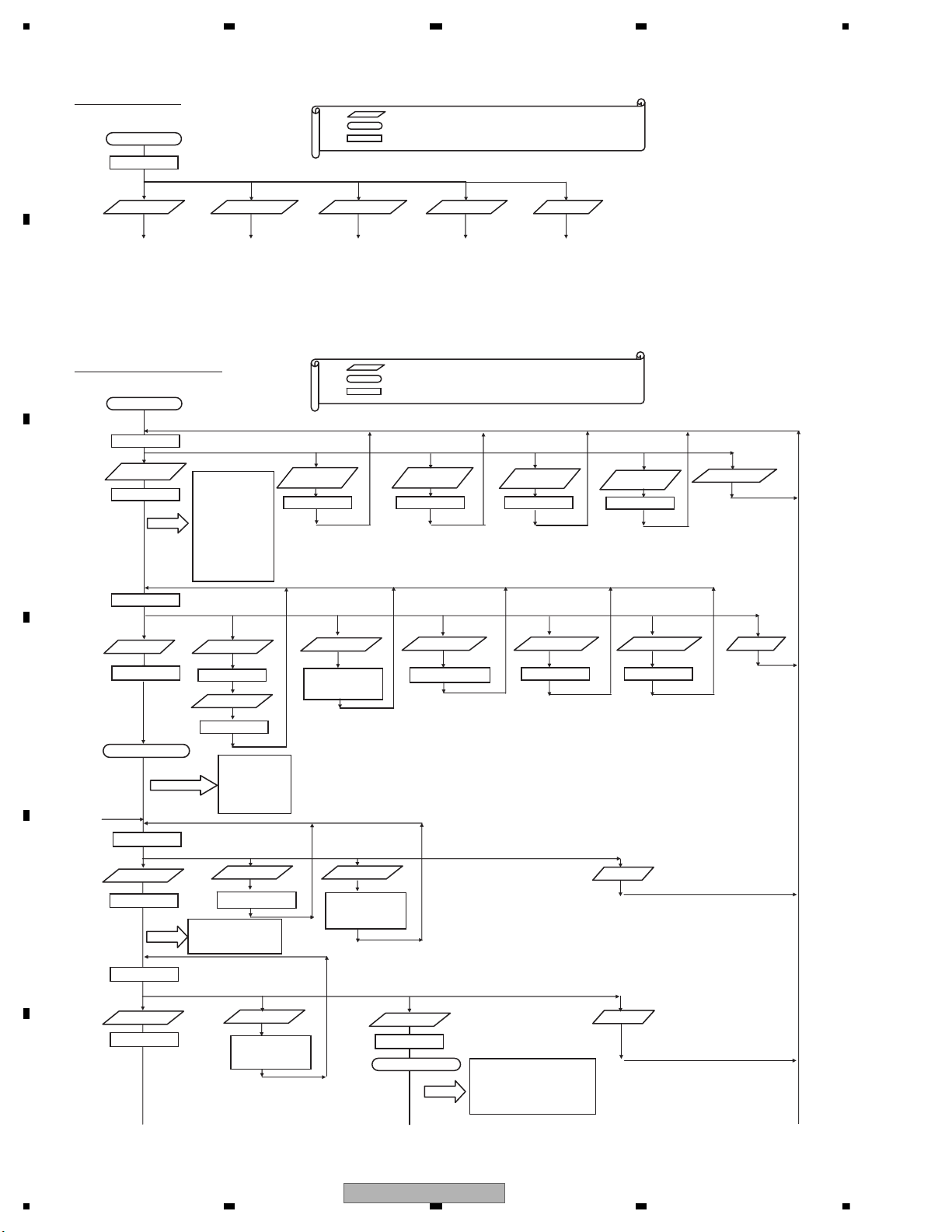
1234
1234
C
D
F
A
B
E
Image of the test mode.
[Note] Higher level 4 characters only. Lower level 4 characters are spaces.
(1) (2) (3) (4) (5)
[Note] In order to move on to another test after selecting a test (FE/EDC1/EDC2), it is necessary to restart the DVD mechanism in the test mode.
Image of the front end test mode.
(1)
(2) (3) (4) (5)
EJECT
(1) (2)
(3),(4)
(5)
(6)
(7) (8)
S curve
measurement
(2)
[Note] If no action is taken for approximately 10 seconds after LD-ON, it will become LO-OFF automatically.
If F close is selected during LD-OFF, it will become an error.
During focus search (S character measurement mode), too, safety regulation applies if LD_OFF is not selected
within 10 seconds. Therefore, even if focus search is selected after LD-ON, it will become LD-OFF after 9 seconds.
In order to F close after focus search (S character measurement mode), set to Power_OFF first then power on again
before F close.
FE test mode
Disc type DVD1
layer
FE offset coefficient
TE offset coefficient
AS offset coefficient
ENV offset coefficient
TG offset coefficient
DBAL coefficient
VIN1 offset cancel value
VIN2 offset cancel value
VIN3 offset cancel value
VIN4 offset cancel value
VIN5 offset cancel value
VIN6 offset cancel value
VIN7 offset cancel value
VIN8 offset cancel value
VIN9 offset cancel value
Power on
F close
F search
1A00 0000
Focus close state
FEMAX level
FEMIN level
ASMAX level
ENVMAX level
FE normalization coefficient
Spindle gain coefficient
TEMAX level indication
TEMIN level indication
CRG+/-
Activates while the key
is being pressed.
1B00 0000 : CRG+
1C00 0000 : CRG-
LD-ON/OFF
When LO-ON : 1100 0000
When LD-OFF : 1000 0000
Power_OFF
Disc type DVD2
layer
Disc type CD
0000 0000
0100 0000 0200 0000
EJECT
Disc type CD-RW
0300 0000
F search STOP
1100 0000
0FFF 0000
1FFF 0000
CRG_HOME
1D00 0000
0X00 0000
Start of the test mode.
TEST
FE test selection EDC1 test selection
EDC2 test selection
Hereafter, to FE test
mode image.
LD power on time
mode selection
Legend:
… Key operation
CRG_OUTSIDER
1E00 0000
Hereafter, to EDC1
test mode image.
Hereafter, to EDC2
test mode image.
Hereafter, to LD power on
time mode image.
Hereafter, to simple
FE test mode.
Simple FE
test mode
… Operation state
… The content displayed on the DVD mechanism (video only)
8 characters data is sent to the product side (HOST) by UART communication.
1X00 0000
(2)
(1)
(2)
(3),(4)
(8)
(1) (3),(4)
(5)
(8)
Tracking balance
TBAL coefficient (layer 0)
TBAL coefficient (layer 1)
TE normalization coefficient (layer 0)
TE normalization coefficient (layer 1)
Off track adjustment result
Focus Jump
When L0 layer : 2000 0000
When L1 layer : 2100 0000
CRG+/-
It operates while the key
is being pressed.
2B00 0000 : CRG+
2C00 0000 : CRG-
Power_OFF
Power_OFF
It operates while the key
is being pressed.
3B00 0000 : CRG+
3C00 0000 : CRG-
2x00 0000
2FFF 0000
3000 0000
3FFF 0000
FBAL coefficient (layer 0)
FBAL coefficient (layer 1)
Focus gain coefficient (layer 0)
Focus gain coefficient (layer 1)
Tracking gain coefficient (layer 0)
Tracking gain coefficient (layer 1)
AS normalization adjustment value (layer 0)
RF level value
3FFF 0000
Tracking close state
Tracking close
CRG+/-
A
B
C
Legend:
… Key operation
… Operation state
… The content displayed on the DVD mechanism (video only)
8 characters data is sent to the product side (HOST) by UART communication.
68
AVH-3400DVD/XUEW5
Page 69
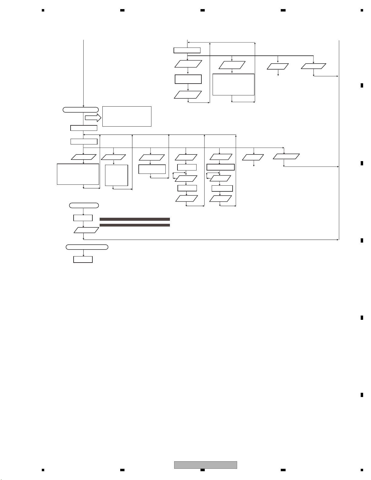
5 678
56
7
8
C
D
F
A
B
E
A
Tracking close state
4000 0000
4x00 0000
(1) (2) (5) (6) (3),(4) (7) (8)
Error rate
measurement
Error rate
Focus gain coefficient (layer 0)
Focus gain coefficient (layer 1)
Tracking gain coefficient (layer 0)
Tracking gain coefficient (layer 1)
AS normalization adjustment value (layer 0)
AS normalization adjustment value (layer 1)
Error occurrence
Error display
(8)
Power_OFF
FBAL coefficient (layer 0)
FBAL coefficient (layer 1)
Focus gain coefficient (layer 0)
Focus gain coefficient (layer 1)
Tracking gain coefficient (layer 0)
Tracking gain coefficient (layer 1)
AS normalization adjustment value (layer 0)
Playback speed
switching
L0 layer DVD X CAV,CD X 2CLV :4000 0000
L0 layer DVD X 1CLV,CD X 1CLV :4200 0000
L1 layer DVD X CAV :4100 0000
L1 layer DVD X 1CLV :4300 0000
L0 layer DVD X 1.3 - 1.6CAV, CD X 4CLV :4000 0000
L0 layer DVD X 1CLV :4200 0000
L1 layer DVD X 1.3 - 1.6CAV :4100 0000
L1 layer DVD X 1CLV :4300 0000
DVDX1.3 -
1.6CAV
CDX4CLV:
4x00 0000
V
V
Change
Focus Jump
When L0 layer : 4x00 0000
When L1 layer : 4x00 0000
B
5000 0000
(1) (2) (7) (8)
RF level value
indication start
RF level is informed
every 500msec.
(1)
RF level value
indication end
ID Search
4A00 0000
(1)-(4)
ID
designation
ID display
(5) (5)
Search
start
The number for designation of the track number shall be selected from the track numbers previously prepared.
Switch to cyclic by (3). Fix by (4).
For CD: Tracks 1, 4, 10, 11 and 32
For DVD: Tracks 1, 4, 10, 11, 32, 64 and 100
Change the method for ID address designation.
Designation of digit by command (1) and (2). UP/DOWN of numbers by command (3) and (4). Fix by command (5).
Error rate
measurement
Error rate
Focus gain coefficient (layer 0)
Focus gain coefficient (layer 1)
Tracking gain coefficient (layer 0)
Tracking gain coefficient (layer 1)
AS normalization adjustment value (layer 0)
AS normalization adjustment value (layer 1)
T.Jump+/-
Jump+ : 4B00 0000
Jump- : 4C00 0000
(3)
Track number
designation
Track number
indication
Jump
start
T.OPEN
To (2)
The higher 2 digits of the designated ID are the value showing the test state.
The lower 6 digits show the ID.
Example) If 300000 is desired to be designated as the ID, designated ID: 4A03 0000.
T.OPEN
To (2)
Power_OFF
Power_OFF
C
Error occurrence at Power_OFF
Error display
[Note] If an error occurs at Power_OFF, reset cannot be made. In such a case, it is necessary to turn the power off and start the test mode once again.
AVH-3400DVD/XUEW5
69
Page 70
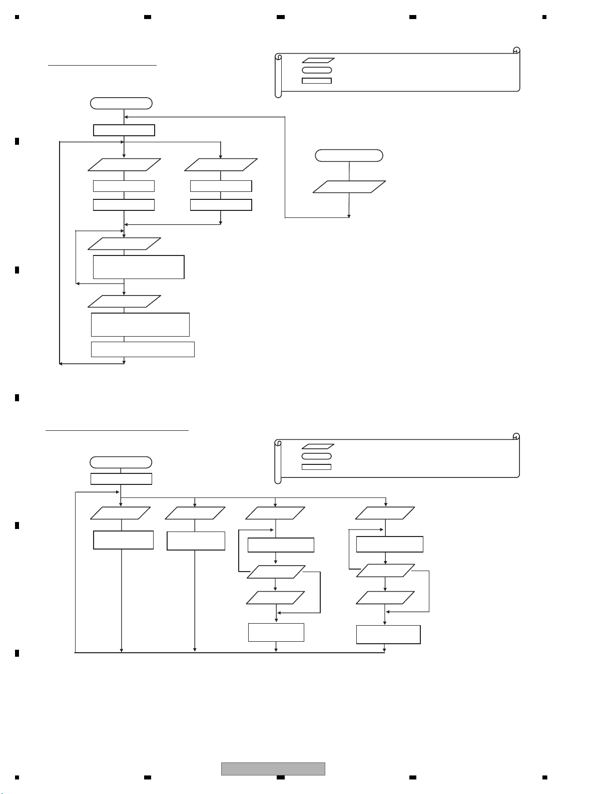
1234
1234
C
D
F
A
B
E
Legend:
… Key operation
… Operational state
… The content displayed on the DVD mechanism (video only)
8 characters data is sent to the product side (HOST) by UART communication.
EDC. Image of the test mode
[Note] Image is the same for both EDC1 and EDC2.
(1) (2)
[Note] Eject can be effected any time during the
EDC test mode.
Eject
After completion of EJECT operation
(5)
[Note] The display is updated at 0.5 seconds interval until 0/1 layer is selected or Eject is effected.
Image of the LD power on time mode.
[Method of setting time designation]
Designate the digit by command (1) and (2). UP/DOWN of numbers by command (3) and (4).
Fix by command (5). Cancel by command (8).
[Note] If the power on time is 999999 hours or more, it is always reported as 999999 hours.
[Note] If the power on time is “*E** ****”, the value may not be correct due to the life of the flash memory.
(1)-(4)
EDC1/2 test mode
0000 0000
Layer 0 selection
Layer 1 selection
ID designation
EDC1/2 start
0000 0000 0100 0000
1003 0000
1103 0000
Layer 1:11** ****
[Note] ** **** is the ID designation value
EJECT operation
Test mode Eject
**** ****
LD power on time mode
0000 0000
CD LD power on
time indication
DVD LD power on
time indication
CD LD power on
time setting
10** ****
[Note] ** **** is the CD LD
power on time.
20** ****
[Note] ** **** is the DVD LD
power on time.
Setting time
designation
30** ****
[Note] ** **** is the setting time.
Setting time
registration
DVD LD power on
time setting
Setting time
designation
40** ****
[Note] ** **** is the setting time.
Setting time
registration
(1)
(2)
(5)
(6)
(1)-(4)
(1)-(4)
(5)
(5)
(8)
(8)
10** ****
[Note] ** **** is the CD LD
power on time.
20** ****
[Note] ** **** is the DVD LD
power on time.
Layer 0:10** ****
[Note] ** **** is the present ID designation value
[Note] **** **** is the present ID designation value
Layer 1:21** ****
Layer 0:20** ****
Legend:
… Key operation
… Operational state
… The content displayed on the DVD mechanism (video only)
8 characters data is sent to the product side (HOST) by UART communication.
70
AVH-3400DVD/XUEW5
Page 71
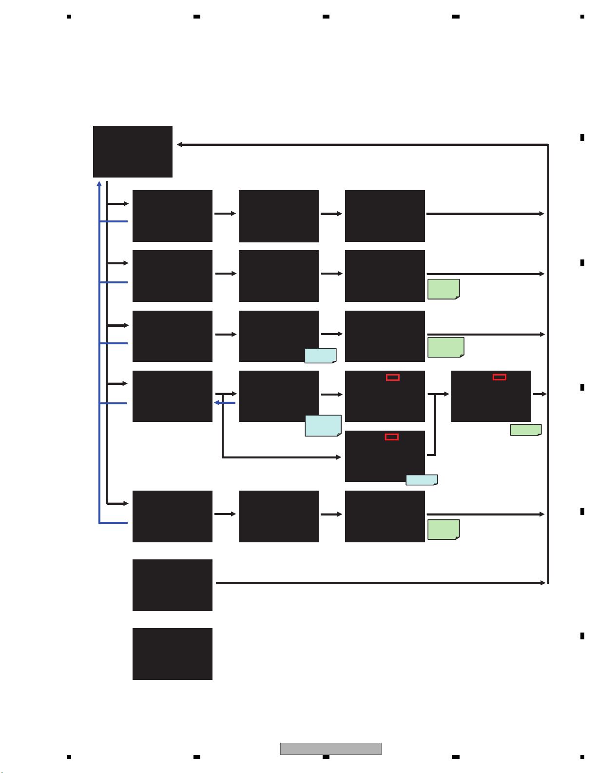
5 678
56
7
8
C
D
F
A
B
E
Simple test mode
The selection of the figure of each screen can be selected by "Key command for the test".
<Flow chart>
TEST MODE
1: LD ON
2: ASMAX
3: Skew Adjustment
4: Error Rate
5: CRG Move Outer
6: Eject
Please Input Number
1 select
5 Return
2 select
5 Return
select
3 select
5 Return
select
4 select
5 Return
5 select
5 Return
select
select
select
LD ON LD ON LD ON
1: DVD Single Layer 1: Power OFF
2: DVD Dual Layer
3: CD
4: CD-RW
5: Return
Please Input Number Now Running Please Input Number
ASMAX ASMAX ASMAX
1: DVD Single Layer 1: Power OFF
2: DVD Dual Layer
3: CD
4: CD-RW
5: Return ASMAX Level : 000000
Please Input Number Now Running Please Input Number
Skew Adjustment Skew Adjustment Skew Adjustment
1: DVD Single Layer 1: Power OFF
5: Return RF Level : 000000
Please Input Number Now Running Please Input Number
Error Rate Error Rate Error Rate - Inner Error Rate - Inner
1: DVD Single Layer 1: Inner Measurement 1: Power OFF
3: CD 3: Middle Measurement
5: Return 5: Return Error Rate : 000000
Please Input Number Please Input Number Now Running Please Input Number
CRG Move Outer CRG Move Outer CRG Move Outer
1: DVD Single Layer 1: Power OFF
2: DVD Dual Layer
3: CD
4: CD-RW
5: Return
Please Input Number Now Running Please Input Number
select
select
select
DVD
select
5 Return
select
CD select
select
2: Outer Measurement
Search ID
0x00100000
Search ID
inner :
0x00040000
outer :
0x00200000
CRG Move
Completion
LD ON
Completion
ASMAX
value set
value set
RF Level
select
Error Rate - CD
Now Running
*1
*1
Search CRG
home position
select
select
ASMAX
Level display
select
RF Level
display
Update 500 msec.
Error Rate
set
select
CRG moves
to the most
outer
*1 : The position in which
select was done is
displayed.
Error Rate -CD
DVD Inner
DVD Outer
DVD Middle
CD CD
*1
Error Rate
display
select
<Error>
ERROR
1: Power OFF
Code : 00000000
Please Input Number
select
<Error : Power OFF>
ERROR
Code : 00000000
Please Reset
AVH-3400DVD/XUEW5
71
Page 72
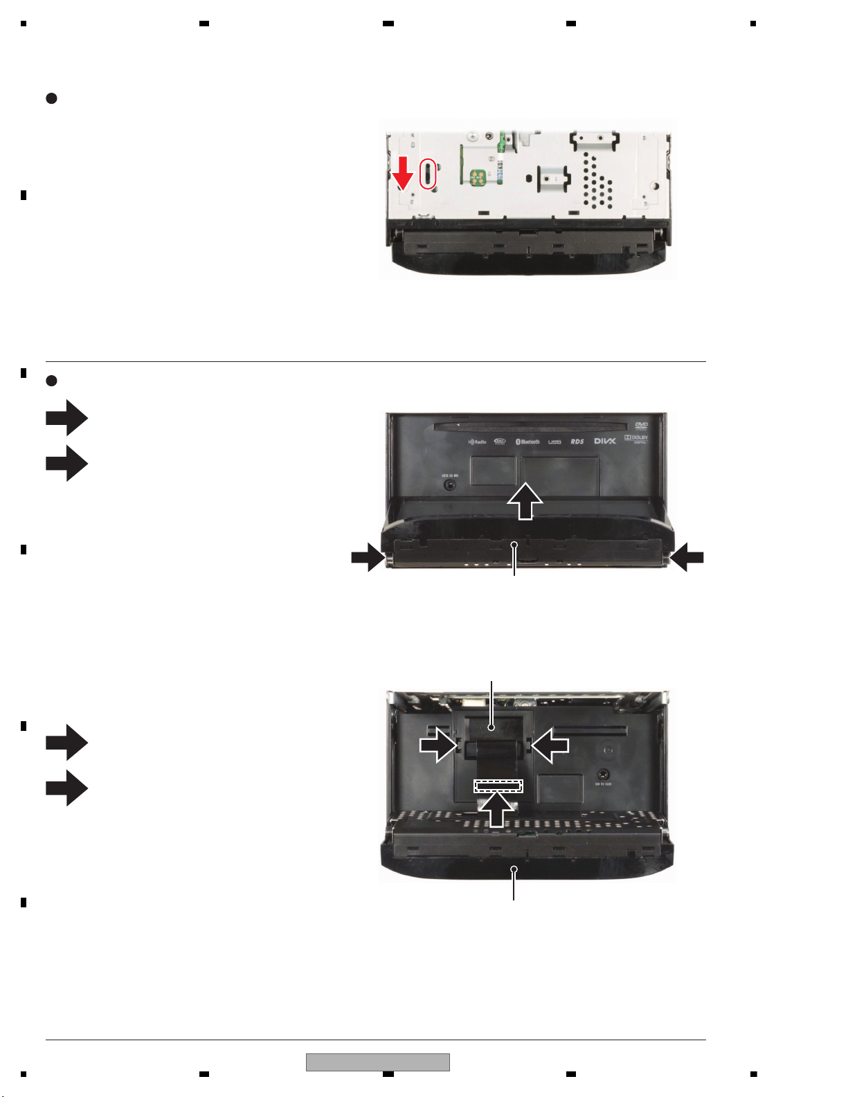
1234
1234
C
D
F
A
B
E
7. DISASSEMBLY
1
2
3
4
1 1
3
3
2
Fig.1
Fig.2
Cover
Insert a tip of screwdriver whose diameter is
approximately 2mm into the slit at the bottom surface
of the product and slide the flame part to the direction
indicated by an arrow.
- Method for opening the flap manually (Fig.1)
- Removing the Monitor Assy (Fig.2)
Monitor Assy
Monitor Assy
Remove the two screws.
Pull out the Monitor Assy in the direction
indicated by an arrow.
Push the two tabs and then remove the Cover.
Disconnect the Connector and then remove
the Monitor Assy.
4
72
AVH-3400DVD/XUEW5
Page 73
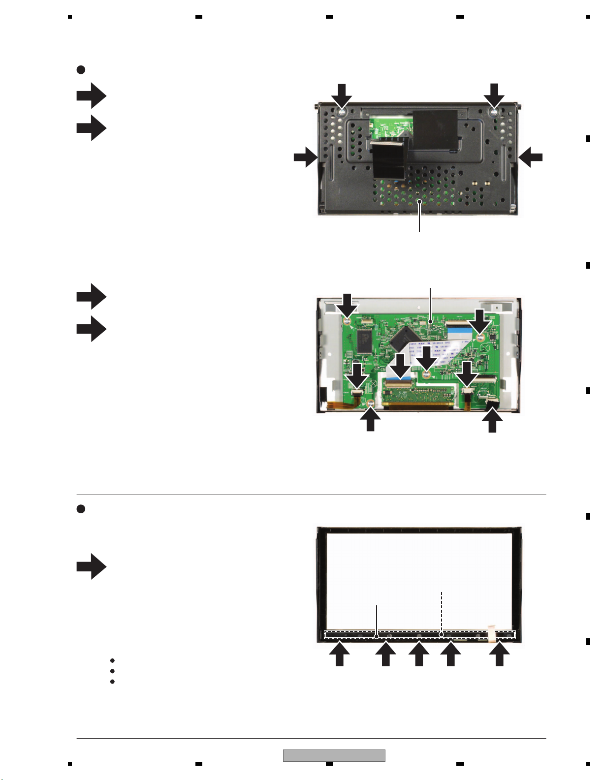
5 678
56
7
8
C
D
F
A
B
E
3
4
1
2
1
1 1
1 1 1 1 1
Case Unit
Holder
Service Unit (Keyboard)
Remove the two screws.
Remove the two screws and then
remove the Case Unit.
3
3
4
3
4
4
3
4
- Removing the Service Unit (Monitor) (Fig.3)
- Removing the Service Unit (Keyboard) (Fig.4)
Service Unit (Monitor)
2
2
Disconnect the four connectors.
Remove the four screws and then remove
the Service Unit (Monitor).
Remove the Grille Assy, LCD and the Touch
Panel.
Release the five latches and then remove
the Holder.
Remove the Service Unit (Keyboard).
After the Service Unit (Keyboard) is replaced,
check the following items.
Check whether all LED's light up
Check the operation of all switches
Check the operation of light receiving part
of the remote controller
Fig.3
Fig.4
AVH-3400DVD/XUEW5
73
Page 74
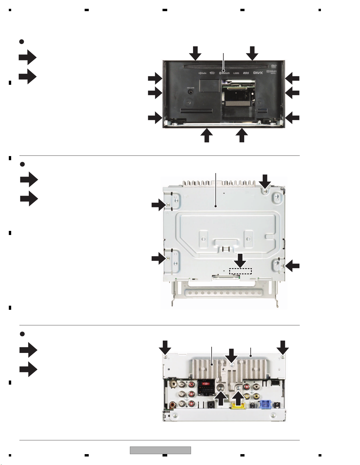
1234
1234
C
D
F
A
B
E
1
2
1
2
3
1
1
1
1 1
1 1
2 2
2 2
2 2
1
1 1
2
2
Fig.5
Fig.6
Fig.7
Remove the four screws.
Release the six latches and then
remove the Panel Assy.
DVD Mechanism Module
- Removing the DVD Mechanism Module (Fig.6)
1
2
Remove the four screws.
Disconnect the connector and then remove the
DVD Mechanism Module.
- Removing the Panel Assy (Fig.5)
Panel Assy
2
1
Remove the three screws and then remove the
Heat Sink.
Remove the two screws and then remove the
Holder.
- Removing the Heat Sink and the Holder (Fig.7)
Holder
Heat Sink
74
AVH-3400DVD/XUEW5
Page 75
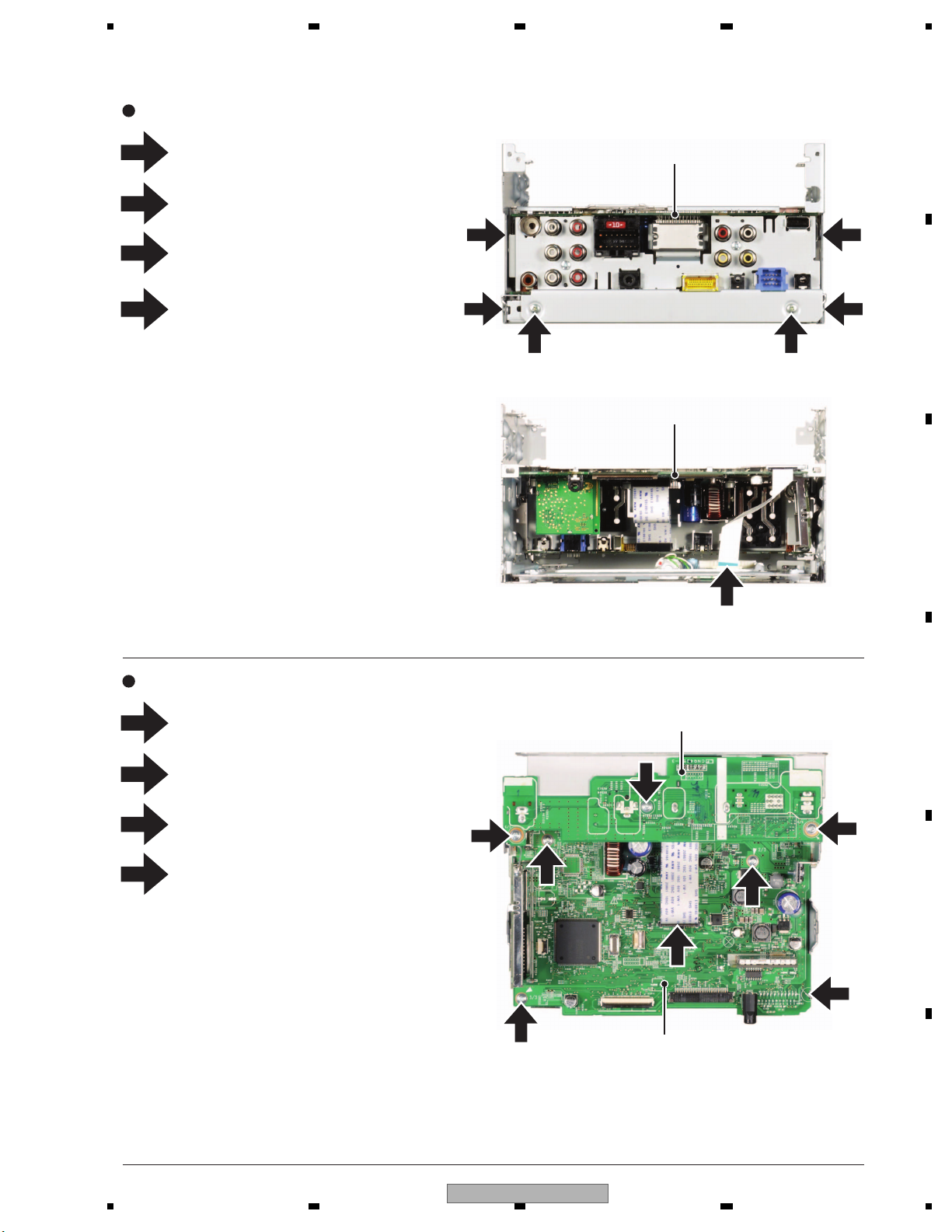
5 678
56
7
8
C
D
F
A
B
E
1
2
3
4
2
1
1
1
2
Fig.8
Fig.9
2
2
3
2
4
4
4
4
- Removing the Mother PCB/IF PCB Section (Fig.8)
1
2
3
4
- Removing the Mother PCB and the IF PCB (Fig.9)
Mother PCB/IF PCB Section
Mother PCB/IF PCB Section
Mother PCB
IF PCB
Remove the two screws.
Remove the two screws.
Loosen the four screws
Disconnect the connector and then remove
the Mother PCB/IF PCB Section.
Disconnect the connector.
Remove the three screws and then remove
the IF PCB.
Straighten the tab.
Remove the three screws and then remove
the Mother PCB.
3 3
(x 2)
(x 2)
AVH-3400DVD/XUEW5
75
Page 76
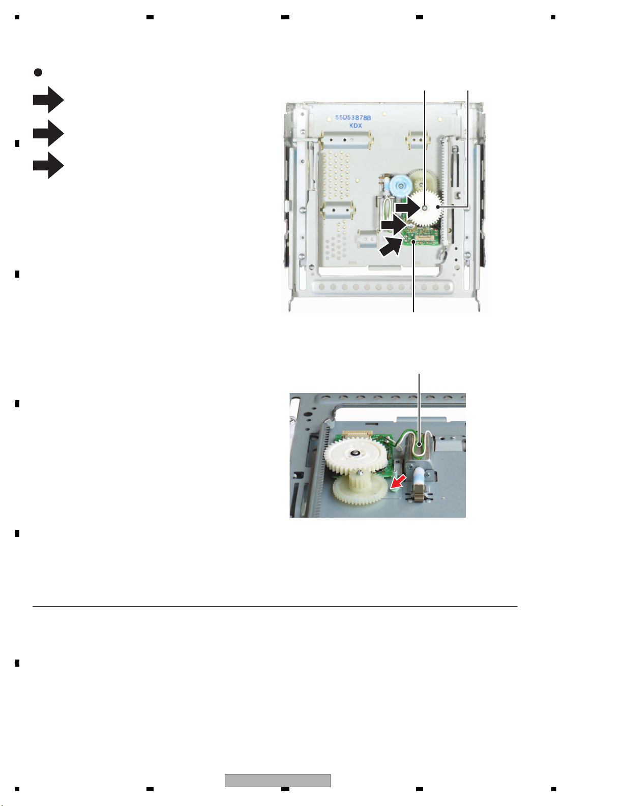
1234
1234
C
D
F
A
B
E
1
2
3
3
2
1
PCB Unit (Service)
Motor Unit
Gear
Fig.10
- Removing the PCB Unit (Service) (Fig.10)
Remove the two solders and then remove
the two cords.
Remove the Washer and then remove the Gear.
Remove the screw and then remove the
PCB Unit (Service).
While withdrawing a Motor Unit to the direction
indicated by an arrow and tighten the screw to
fix it. If you tighten the screw after withdrawing
it to the opposite direction of the arrow, the
pitch between Worm Gear and Worm Wheel
opens up and the gear jumps due to drop of
package and abnormal sound may be
generated.
Precautions on attachment of Motor Unit.
Washer
76
AVH-3400DVD/XUEW5
Page 77
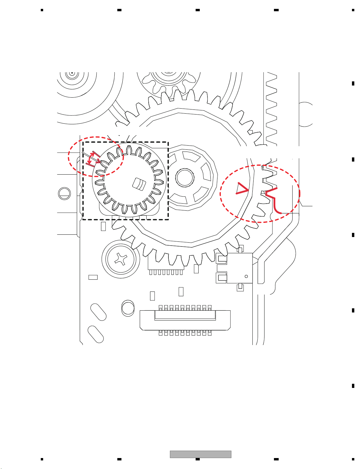
5 678
56
7
8
C
D
F
A
B
E
The cutting lack of the Gear (ENV1635) is put between signs of the PCB.
The point of the Frame (ENC2001) is set to
the position of the mark of the Gear (ENV1630).
AVH-3400DVD/XUEW5
77
Page 78

1234
1234
C
D
F
A
B
E
8. EACH SETTING AND ADJUSTMENT
This product uses 5 V and 3.3 V as standard voltages.
The electrical potential that is the reference for signals, is not GND, but VREF (approximately 2.2 V) and VHALF
(approximately 1.65 V) .
During product adjustments, if the reference voltage is mistakenly taken as GND, and a grounding contact is made,
not only would it be impossible to measure the accurate electrical potential, but also the servo motor
would malfunction, resulting in the application of a strong impact on the pick up.
The following precautionary measures should be strictly adhered to, in order to avoid such problems.
The reference voltage and GND should not be confused when using the minus probe of a measurement device.
When an oscilloscope is being used special care should be taken to make sure that the reference voltage is not
connected to the probe of ch1 (on the minus side), while the probe of ch2 (on the minus side), is connected to GND.
Further, since the body frame of most measurement devices have the same electrical potential as the minus side of
the probe, the body frame of the measurement device should be set to floating ground.
If the reference voltage is connected to GND by mistake, turn the regulator OFF immediately, or turn the power OFF.
Remove the filters and wires used for measurements only after the regulator has been turned OFF.
After the power supply is turned on, regulator ON the following adjustment and measurement are promptly done.
Whenever the product is in the test mode, the software will not take any protective action. For this reason, special
care should be taken to make sure that no mechanical or electrical shock could be applied to the product when
taking measurements in the test mode.
Whenever the EJECT key is pressed to eject the disk, no other keys, other than the EJECT key, should be pressed
until the disk eject action has been completed.
Press the EJECT key only after the disk has stopped completely.
If the product hangs up turn the power OFF immediately.
Don't touch the volume for laser power adjustment other than the time of POWER adjustment.
(Laser diode may be damaged.)
8.1 DVD ADJUSTMENT
78
AVH-3400DVD/XUEW5
Page 79
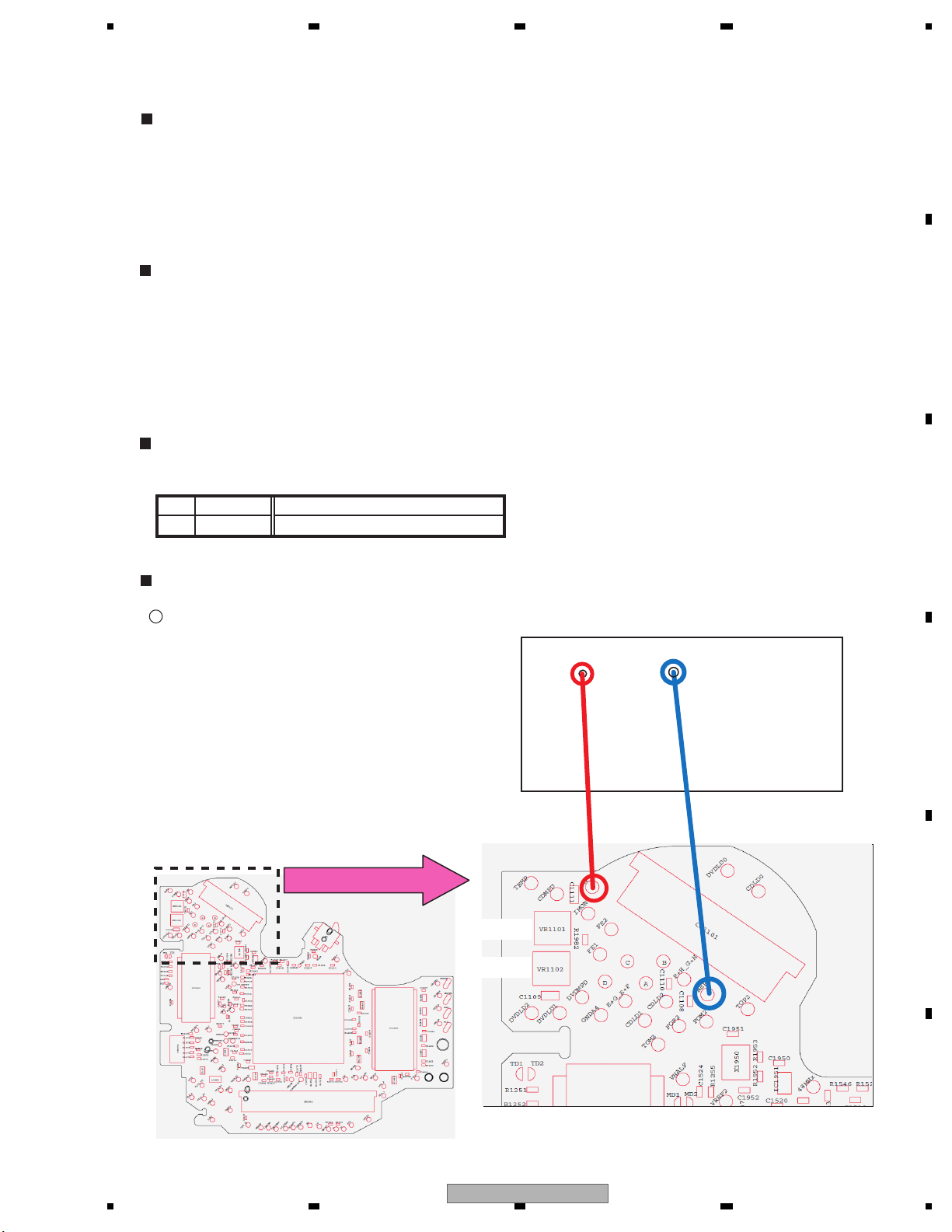
5 678
56
7
8
C
D
F
A
B
E
Power adjustment
Power adjustment
Enlarged
- Power Adjustment
Power Adjustment
To turn VR of the circuit for Power adjustment and adjust the optical output level of PU laser diode to make the level
of signal (RF signal) read from the media appropriate level during the reproduction of media, CD and DVD.
It has been decided that Power adjustment circuit (circuit from IMON to CDMP, DVDMP) which adjusts the optical
output level of PU laser diode should be installed on DVD Core Unit in the DVD mecha module.
Therefore, in the replacement of CRG mecha (with PU unit) and DVD Core Unit, Power adjustment should be
implemented.
The Power adjustment method of mecha module is shown below.
Items to be Prepared
Measuring instrument: Oscilloscope (digital or analog)
Frequency band of oscilloscope in DVD whose frequency is higher than CD Adjustable 10 MHz
and higher (enough to check the level)
(In LS2, DVD (x 1.5CLV) MAX RF 6.55 MHz / DVD (x 1.5CLV) MIN RF 1.40 MHz)
DISC: DVD TEST DISC (TDV-582 or TDV-520) Almedio
CD TEST DISC (TCD-782 or TCD-792) Almedio
Adjustment screwdriver : crosshead, No.0, nonmetal (ceramic screwdriver for adjustment)
Line Locating
The following line locating is required.
1RF
2 VREF1
Connection Diagram
: Checking terminal for oscilloscope
The figure in parentheses of resistor / capacitor is constant.
For CDt
For DVDt
Universal board
RF
VREF1
AVH-3400DVD/XUEW5
79
Page 80
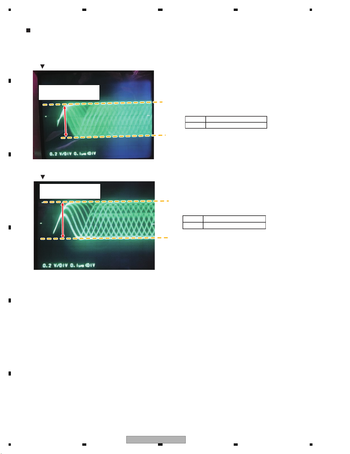
1234
1234
C
D
F
A
B
E
Method of Power Adjustment
1. Monitor RF by using the analog oscilloscope. (line locating of RF and VREF1)
2. Turn VR1101 and VR1102 to set the PP value of RF at the value shown in the right lower table.
RF waveform after F-ON / before T-ON (waveform measured by analog oscilloscope)
Power adjustment standard
RF level adjustment value
(F-ON STEP 10, 24)
DVD
CD
RF waveform after the completion of all adjustment (waveform measured by analog oscilloscope)
DVD
848 mV to 892 mV
CD 658 mV to 702 mV
200 mV to 1200 mV
200 mV to 1200 mV
Adjust VR in order that this
width is within the range of
target RF level adjustment value.
Adjust VR in order that this
width is within the range of
target FR level adjustment value.
Power adjustment standard
RF level adjustment value
(The setup is completed. STEP 12, 26)
80
AVH-3400DVD/XUEW5
Page 81
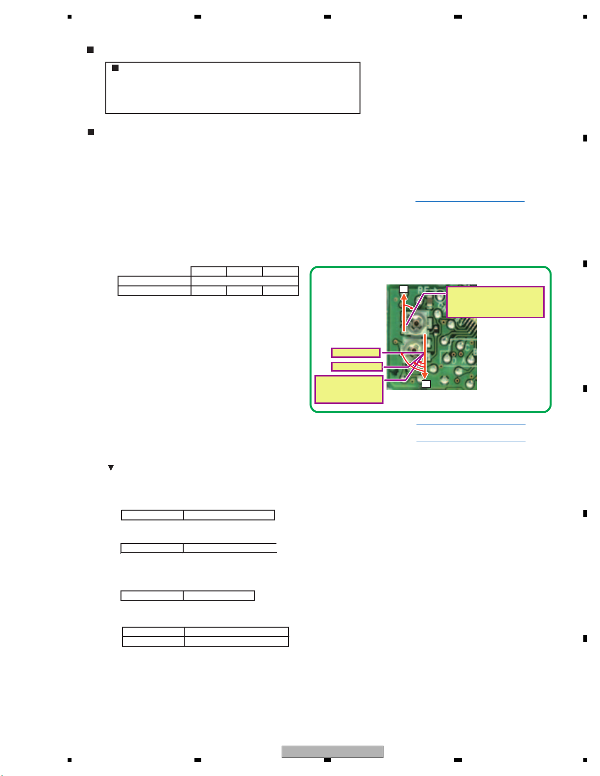
5 678
56
7
8
C
D
F
A
B
E
Procedure of Power Adjustment
Flow
1. DVD Power adjustment in the state where F is ON
2. DVD Power adjustment in the state where the setup is completed
3. CD Power adjustment in the state where F is ON
4. CD Power adjustment in the state where the setup is completed
Procedure of Adjustment
STEP No.
1. Set the mecha to clockwise.
2. Turn on power.
3. Test Mode In
4. Insert DVD TDV-582 (or TDV-520).
Refer to FE test mode function flow.
5. Set the mecha to counterclockwise.
6. Adjustment of the initial position of VR for Power adjustment
Adjust the angle at the D cut position to the initial position
(initial position shown in Fig.1).
1st 2nd 3rd
CD (VR1101)
DVD (VR1102) -30°
7. Set DISC TYPE to DVD single layer.
8. Power on.
9. LD-ON
10. Execute until Focus close state is reached.
If the waveform is similar to RF waveform after F-ON and before T-ON (waveform measured by analog oscilloscope), Focus Close is reached.
Go to STEP 9.
If the RF waveform does not appear, Focus Close is not reached.
Return to STEP 7 and change the angle of initial position of DVD VR (VR 1102). If Focus Close is not reached after the 3rd VR adjustment,
replace the whole CRG mecha (including PU unit) and start again from STEP 1.
DVD
200 mV to 1200 mV
-30°
-45° -90°
3rd - -90°
2nd - -45°
DVD VR (VR1102)
Adjustment of the initial
position
1st - -30°
0°
Refer to FE test mode function flow.
Refer to FE test mode function flow.
Refer to FE test mode function flow.
CD VR (VR1101)
Adjustment of the initial position
-30° - 1st, 2nd, 3rd is the same, too
0°
Fig.1
11. Conduct Power adjustment. (Conduct the adjustment in the state of Focus Close.)
DVD
848 mV to 892 mV
12. Execute until Tracking Close is reached.
13. Conduct Power adjustment. (Conduct the adjustment in the state of Tracking Close.)
DVD
2.0E – 4 and under
14. Check the ERR rate after Power adjustment.
DVD
DVD
820 mV to 917 mV
2.0E – 4 and under
15. Power off.
16. Return the state of mecha to clockwise.
17. Set up again (state of mecha to clockwise / setting of DVD single layer) and conduct the final check of RF level and ERR rate.
(Check in the state of Tracking Close)
18. Eject.
AVH-3400DVD/XUEW5
81
Page 82
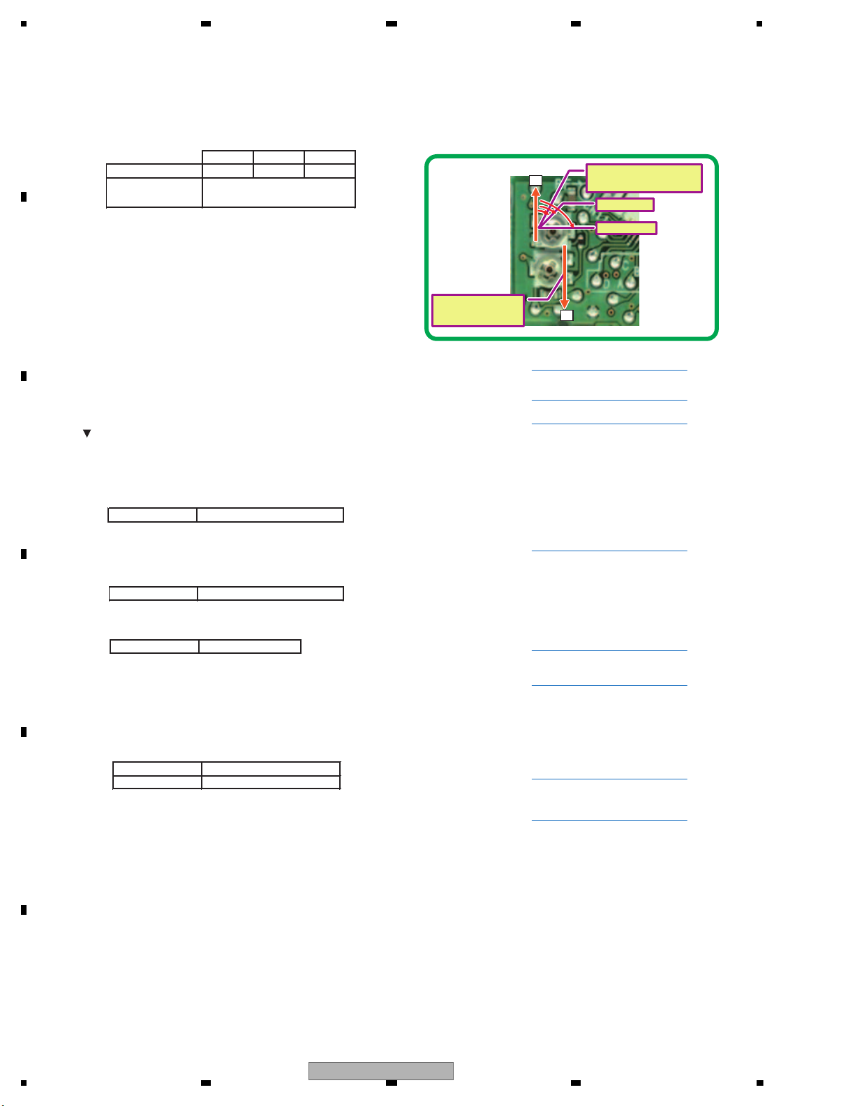
1234
1234
C
D
F
A
B
E
19. Take out DVD TDV-582 (or TDV-520).
Insert CD TCD-782 (or TCD-792).
20. Set the mecha counterclockwise.
21. Adjustment of the initial position of VR for Power adjustment
22. Set DISC TYPE to CD.
23. Power on.
24. Execute until Focus Close 1 is reached.
If the waveform is similar to RF waveform after F-ON and before T-ON (waveform measured by analog oscilloscope), Focus Close is reached.
Go to STEP 20.
If the RF waveform does not appear, Focus Close is not reached. Return to STEP 21 and change the angle of initial position of CD VR (VR1101).
If Focus Close is not reached after the 3rd VR adjustment, replace the whole CRG mecha (including PU unit) and start again from STEP 1.
25. Conduct Power adjustment. (Conduct the adjustment in the state of Focus Close.)
26. Execute until Tracking Close is reached.
27. Conduct Power adjustment. (Conduct the adjustment in the state of Focus Close.)
28. Check ERR rate.
29. Power off.
30. Return the state of mecha to clockwise.
31. Set up again (state of mecha to clockwise / setting of CD layer), and conduct the final check of RF level and ERR rate.
(Check in the state of Tracking Close)
32. Eject.
33. Take out CD TCD-782 (or TCD-792).
34. Power off.
Adjust the angle at the D cut position to the initial position
(initial position shown in Fig.2).
1st
2nd
3rd
CD (VR1101)
-30°
-45° -90°
DVD
(VR1102)
CD
CD
CD
CD
CD
528 mV to 832 mV
1.0E – 2 and under
200 mV to 1200 mV
658 mV to 702 mV
As the adjustment is
completed, never change.
0°
0°
CD VR (VR1101)
Adjustment of the initial position
1st - 30°
DVD VR (VR1102)
As the adjustment is
completed, never change.
3rd - -90°
2nd - -45°
1.0E – 2 and under
Refer to FE test mode function flow.
Refer to FE test mode function flow.
Refer to FE test mode function flow.
Refer to FE test mode function flow.
Refer to FE test mode function flow.
Refer to FE test mode function flow.
Refer to FE test mode function flow.
Refer to FE test mode function flow.
Fig.2
82
AVH-3400DVD/XUEW5
Page 83

5 678
56
7
8
C
D
F
A
B
E
- PCL Output
With the TESTIN (149 pin)(TP : TSIN) status of IC602 to be “H”, it is shifted to PCL Output Test mode after reset started.
The clock signal is output from the CLKOUT terminal IC602 (Pin 106)(TP : CKOT) .
The frequency of the clock signal is 47.18592 MHz.
If the clock signal out of the range, the X’tal (X601) should be replaced with new one.
8.2 PCL OUTPUT CONFIRMATION
AVH-3400DVD/XUEW5
83
Page 84
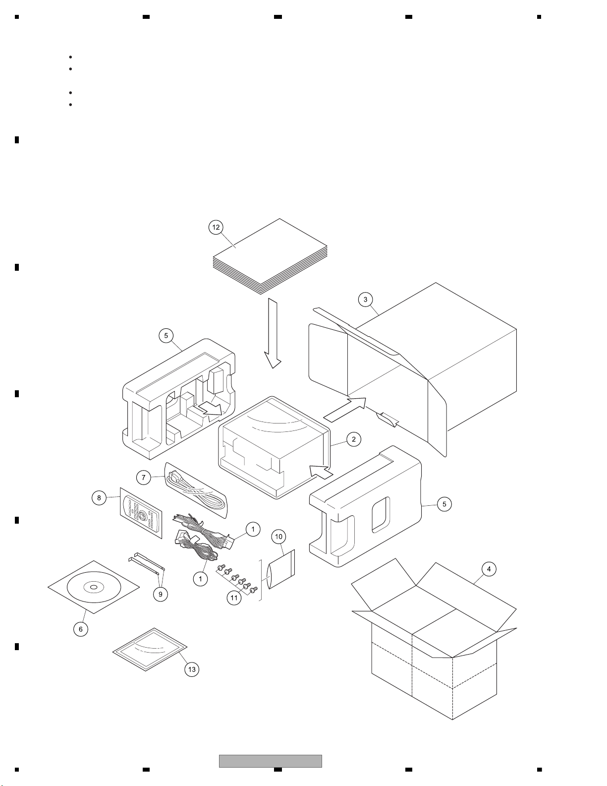
1234
1234
C
D
F
A
B
E
9. EXPLODED VIEWS AND PARTS LIST
NOTES : Parts marked by " * " are generally unavailable because they are not in our Master Spare Parts List.
The > mark found on some component parts indicates the importance of the safety factor of the part.
Therefore, when replacing, be sure to use parts of identical designation.
Screw adjacent to mark on the product are used for disassembly.
For the applying amount of lubricants or glue, follow the instructions in this manual.
(In the case of no amount instructions,apply as you think it appropriate.)
"
RC, RD, RI, ID
RC, RD, RI, ID
RC, RD, RI, ID
RC, RD, RI, ID
EW5, UW5, RI
EW5, UW5
EW5
9.1 PACKING
84
AVH-3400DVD/XUEW5
Page 85
5 678
56
7
8
C
D
F
A
B
E
(1) PACKING SECTION PARTS LIST
Mark
Mark No. Description Part No.
1 Cord Assy See Contrast table (2)
2 Cover CEG1356
3 Unit Box See Contrast table (2)
4 Contain Box See Contrast table (2)
5 Protector See Contrast table (2)
No. Description Part No.
11 Screw See Contrast table (2)
12-1 Owner's Manual See Contrast table (2)
12-2 Owner's Manual See Contrast table (2)
12-3 Owner's Manual See Contrast table (2)
12-4 Installation Manual See Contrast table (2)
6 IM CD-ROM See Contrast table (2)
7 Cord Assy YDP5047
8 Card Remote Control Unit See Contrast table (2)
9 Handle See Contrast table (2)
* 10 Polyethylene Bag See Contrast table (2)
(2) CONTRAST TABLE
* 12-5 Caution Card See Contrast table (2)
* 12-6 Caution Card See Contrast table (2)
* 12-7 Warranty Card See Contrast table (2)
* 12-8 Service Network See Contrast table (2)
13 Panel See Contrast table (2)
AVH-3400DVD/XUEW5, AVH-P3400DVD/XUUW5, AVH-P3450DVD/XURC, AVH-P3450DVD/XURD, AVHP3450DVD/XURI and AVH-P3490DVD/XUID are constructed the same except for the following:
Mark No. Description
1 Cord Assy CDP1436 CDP1436 CDP1435 CDP1435 CDP1435
3 Unit Box CHG8012 CHG8014 CHG8059 CHG8016 CHG8060
4 Contain Box CHL8012 CHL8014 CHL8059 CHL8016 CHL8060
5 Protector CHP3708 CHP3708 CHP3951 CHP3951 CHP3708
6 IM CD-ROM CPJ1389 Not used Not used Not used Not used
8 Card Remote
Control Unit
9 Handle CND6289 CND6289 Not used Not used CND6289
10 Polyethylene Bag Not used Not used CEG1160 CEG1160 CEG1160
11 Screw Not used Not used TRZ50P080FTC TRZ50P080FTC TRZ50P080FTC
12-1 Owner's Manual CRD4599
AVH-3400DVD/
XUEW5
Not used Not used CXE5116 CXE5116 CXE5116
(Quick Start Guide)
AVH-P3400DVD/
XUUW5
CRB3731 CRB3733 CRB3733 CRB3733
AVH-P3450DVD/
XURC
AVH-P3450DVD/
XURD
AVH-P3450DVD/
XURI
12-2 Owner's Manual CRD4600
12-3 Owner's Manual Not used Not used Not used CRB3737 CRB3739
12-4 Installation Manual CRD4601 Not used Not used Not used Not used
* 12-5 Caution Card CRP1436 Not used Not used Not used Not used
* 12-6 Caution Card CRP1441 Not used Not used Not used Not used
* 12-7 Warranty Card CRY1279 CRY1330 Not used Not used Not used
* 12-8 Service Network Not used Not used Not used Not used Not used
13 Panel Not used Not used CNS9475 CNS9475 CNS9475
Mark No. Description
1 Cord Assy CDP1435
3 Unit Box CHG8061
4 Contain Box CHL8061
5 Protector CHP3951
6 IM CD-ROM Not used
8 Card Remote
Control Unit
9 Handle Not used
10 Polyethylene Bag CEG1160
11 Screw TRZ50P080FTC
12-1 Owner's Manual CRB3743
12-2 Owner's Manual Not used
12-3 Owner's Manual Not used
12-4 Installation Manual Not used
* 12-5 Caution Card Not used
* 12-6 Caution Card Not used
(Quick Start Guide)
AVH-P3490DVD/
XUID
CXE5116
CRB3903 CRB3734 CRB3736 CRB3738
AVH-3400DVD/XUEW5
85
Page 86
1234
1234
C
D
F
A
B
E
Mark No. Description
* 12-7 Warranty Card CRY1304
* 12-8 Service Network CRY1305
13 Panel CNS9475
Owner's Manual,Installation Manual
Part No. Language
CRD4599 English, French, Italian, Spanish(Espanol)
CRD4600 German, Dutch
CRD4601 English, French, Italian, Spanish(Espanol), German, Dutch
CRB3731 English
CRB3732 Russian
CRB3733 English
CRB3734 Traditional Chinese
CRB3736 Spanish(Espanol)
CRB3737 Portuguese(B)
CRB3738 Arabic
CRB3739 Persian
CRB3743 English
AVH-P3490DVD/
XUID
CONTENTS OF CD-ROM (Operation Manual), CPJ1389
Part No. Language
* CRB3715 English
* CRB3716 French
* CRB3717 Italian
* CRB3718 Spanish(Espanol)
* CRB3719 German
* CRB3720 Dutch
* CRB3721 Swedish
* CRB3722 Norwegian
* CRB3723 Finnish
* CRB3724 Danish
* CRB3725 Portuguese
* CRB3726 Greek
* CRB3727 Turkish
All operation manuals are supplied in PDF files by the CD-ROM.
Regarding the availability of paper manual, contact Pioneer Service representative in your region.
86
AVH-3400DVD/XUEW5
Page 87

5 678
56
7
8
C
D
F
A
B
E
AVH-3400DVD/XUEW5
87
Page 88
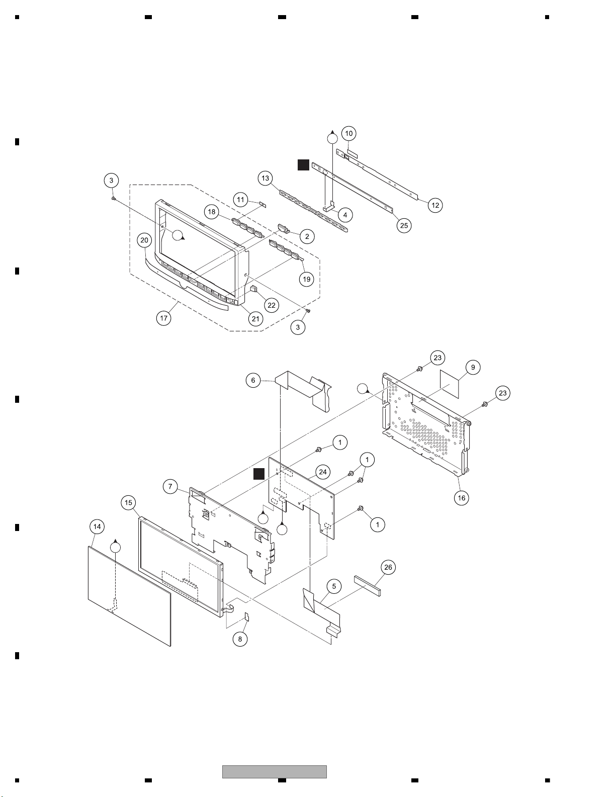
1234
1234
C
D
F
A
B
E
9.2 EXTERIOR (1)
A
D
E
B
B
C
A
C
88
AVH-3400DVD/XUEW5
Page 89
5 678
56
7
8
C
D
F
A
B
E
(1) EXTERIOR (1) SECTION PARTS LIST
Mark
Mark No. Description Part No.
1 Screw AMZ20P030FTC
2 Button (HOME) CAI3686
3 Screw CBA1877
4 FFC CDE9393
5 FFC CDE9472
6 FFC CDE9550
7 Holder CND6218
8 Sheet CNN3728
9 Sheet CNN3988
10 Sheet CNN3991
11 Sheet CNN4033
12 Holder CNU1756
13 Lighting Conductor CNW2312
14 Touch Panel CSX1165
No. Description Part No.
15 LCD CWX3867
16 Case Unit CXE5477
17 Grille Assy See Contrast table (2)
18 Button (SRC, VOL+/-, MUTE) CAI3613
19 Button (MODE, TRK UP/DOWN, EJECT) CAI3690
20 Plate See Contrast table (2)
21 Grille CNU1736
22 Lighting Conductor CNW2313
23 Screw IMS20P030FTC
24 Service Unit (Monitor) See Contrast table (2)
25 Service Unit (Keyboard) CXX4182
26 Spacer CNN4135
(2) CONTRAST TABLE
AVH-3400DVD/XUEW5, AVH-P3400DVD/XUUW5, AVH-P3450DVD/XURC, AVH-P3450DVD/XURD, AVHP3450DVD/XURI and AVH-P3490DVD/XUID are constructed the same except for the following:
Mark No. Description
17 Grille Assy CXE4849 CXE4845 CXE4850 CXE4850 CXE4850
20 Plate CNN3868 CNN3864 CNN3869 CNN3869 CNN3869
24 Service Unit (Monitor) CXX4179 CXX4179 CXX4552 CXX4179 CXX4179
AVH-3400DVD/
XUEW5
AVH-P3400DVD/
XUUW5
AVH-P3450DVD/
XURC
AVH-P3450DVD/
XURD
AVH-P3450DVD/
XURI
Mark No. Description
17 Grille Assy CXE4851
20 Plate CNN3870
24 Service Unit (Monitor) CXX4179
AVH-P3490DVD/
XUID
AVH-3400DVD/XUEW5
89
Page 90
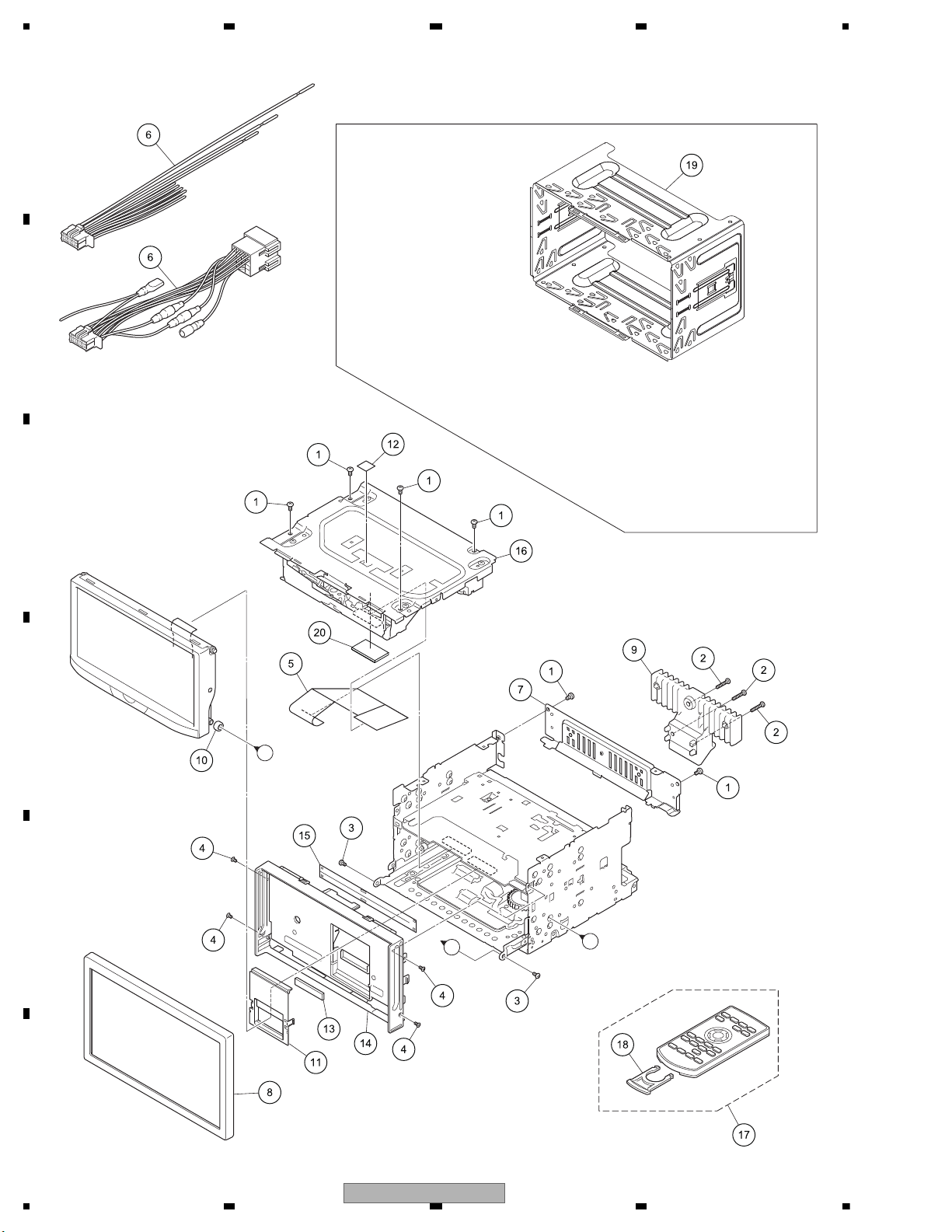
1234
1234
C
D
F
A
B
E
9.3 EXTERIOR (2)
A
A
ID
EW5, UW5, RI
EW5, UW5
RC, RD, RI, ID
RC, RD, RI, ID
RD
B
90
AVH-3400DVD/XUEW5
Page 91
5 678
56
7
8
C
D
F
A
B
E
(1) EXTERIOR (2) SECTION PARTS LIST
Mark
Mark No. Description Part No.
1 Screw BSZ26P050FTC
2 Screw BSZ26P180FTC
3 Screw CBA1735
4 Screw (M2 x 3) CBA1877
5 FFC CDE9545
No. Description Part No.
11 Cover CNW2316
12 Label See Contrast table (2)
13 Cushion CNN3206
14 Panel CNU1759
15 Cover CNN1665
6 Cord Assy See Contrast table (2)
7 Holder CND6246
8 Panel See Contrast table (2)
9 Heat Sink CNR2113
10 Collar CNW2038
(2) CONTRAST TABLE
16 DVD Mechanism Module (LS2) CXK8002
17 Card Remote Control Unit See Contrast table (2)
18 Cover See Contrast table (2)
19 Holder See Contrast table (2)
20 Spacer See Contrast table (2)
AVH-3400DVD/XUEW5, AVH-P3400DVD/XUUW5, AVH-P3450DVD/XURC, AVH-P3450DVD/XURD, AVHP3450DVD/XURI and AVH-P3490DVD/XUID are constructed the same except for the following:
Mark No. Description
6 Cord Assy CDP1436 CDP1436 CDP1435 CDP1435 CDP1435
8 Panel CNS8665 CNS8665 Not used Not used CNS8665
12 Label Not used Not used Not used Not used Not used
17 Card Remote
Control Unit
18 Cover Not used Not used CNU1624 CNU1624 CNU1624
19 Holder CND6288 CND6288 Not used Not used CND6288
20 Spacer
Mark No. Description
6 Cord Assy CDP1435
8 Panel Not used
12 Label CNN3533
17 Card Remote
Control Unit
18 Cover CNU1624
19 Holder Not used
20 Spacer Not used
AVH-3400DVD/
XUEW5
Not used Not used CXE5116 CXE5116 CXE5116
Not used Not used
AVH-P3490DVD/
XUID
CXE5116
AVH-P3400DVD/
XUUW5
AVH-P3450DVD/
XURC
Not used CNN4042
AVH-P3450DVD/
XURD
AVH-P3450DVD/
XURI
Not used
AVH-3400DVD/XUEW5
91
Page 92
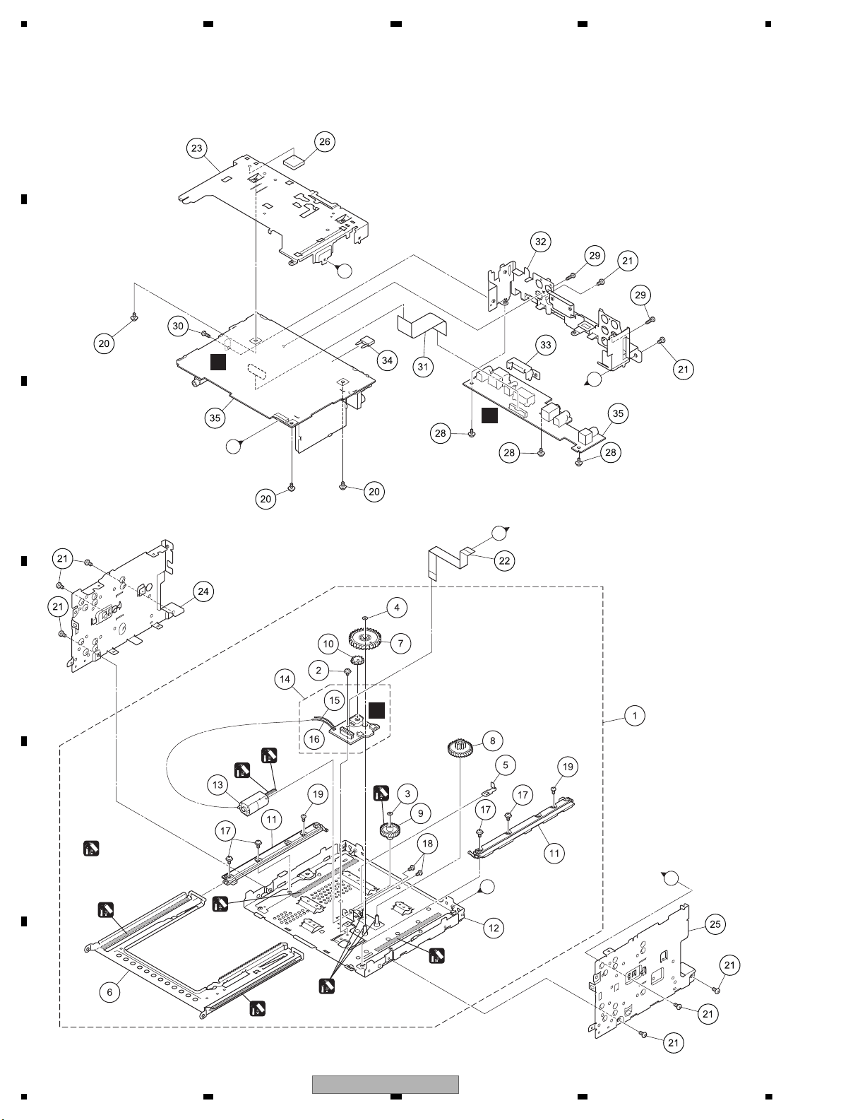
1234
1234
C
D
F
A
B
E
9.4 EXTERIOR (3)
F
(A) : GEM1024
(B) : GEM1043
(B)
(B)
(B)
(B)
(B)
(B)
(A)
(A)
A
B
A
B
A
B
Spreads grease on
the entire gear.
Spreads grease
on tip of gear.
-1
-2
C
C
92
AVH-3400DVD/XUEW5
Page 93
5 678
56
7
8
C
D
F
A
B
E
(1) EXTERIOR (3) SECTION PARTS LIST
Mark
Mark No. Description Part No.
1 Drive Unit CXE4058
2 Screw AMZ26P030FTC
3 Washer CBF1039
4 Washer CBF1064
5 Spring EBL1034
6 Frame ENC2001
7 Gear ENV1630
8 Gear ENV1631
9 Gear ENV1632
10 Gear ENV1635
11 Guide ENV3001
12 Chassis Unit EXA4001
13 Motor Unit EXA4003
14 PCB Unit (Service) EXX2001
* 15 Cord (Green) CDC1056
* 16 Cord (White) CDC1057
17 Screw IMS26P060FTC
18 Screw JFZ20P025FTC
No. Description Part No.
19 Screw EBA2002
20 Screw ASZ26P050FTC
21 Screw BSZ26P050FTC
22 FFC CDE9554
23 Holder CND6247
24 Bracket CND6275
25 Bracket CND6335
26 Sheet CNN3994
27 •••••
28 Screw ASZ26P050FTC
29 Screw BPZ26P080FTC
30 Screw BSZ26P080FTC
31 FFC CDE9546
32 Holder See Contrast table (2)
33 Holder CND4814
34 Fuse (10 A) YEK5001
>
35 Service Unit (Mother I/F) See Contrast table (2)
(2) CONTRAST TABLE
AVH-3400DVD/XUEW5, AVH-P3400DVD/XUUW5, AVH-P3450DVD/XURC, AVH-P3450DVD/XURD, AVHP3450DVD/XURI and AVH-P3490DVD/XUID are constructed the same except for the following:
Mark No. Description
32 Holder CND6315 CND6316 CND6316 CND6316 CND6316
35 Service Unit (Mother I/F) CXX4164 CXX4165 CXX4166 CXX4167 CXX4168
Mark No. Description
32 Holder CND6316
35 Service Unit (Mother I/F) CXX4169
AVH-3400DVD/
XUEW5
AVH-P3490DVD/
XUID
AVH-P3400DVD/
XUUW5
AVH-P3450DVD/
XURC
AVH-P3450DVD/
XURD
AVH-P3450DVD/
XURI
AVH-3400DVD/XUEW5
93
Page 94
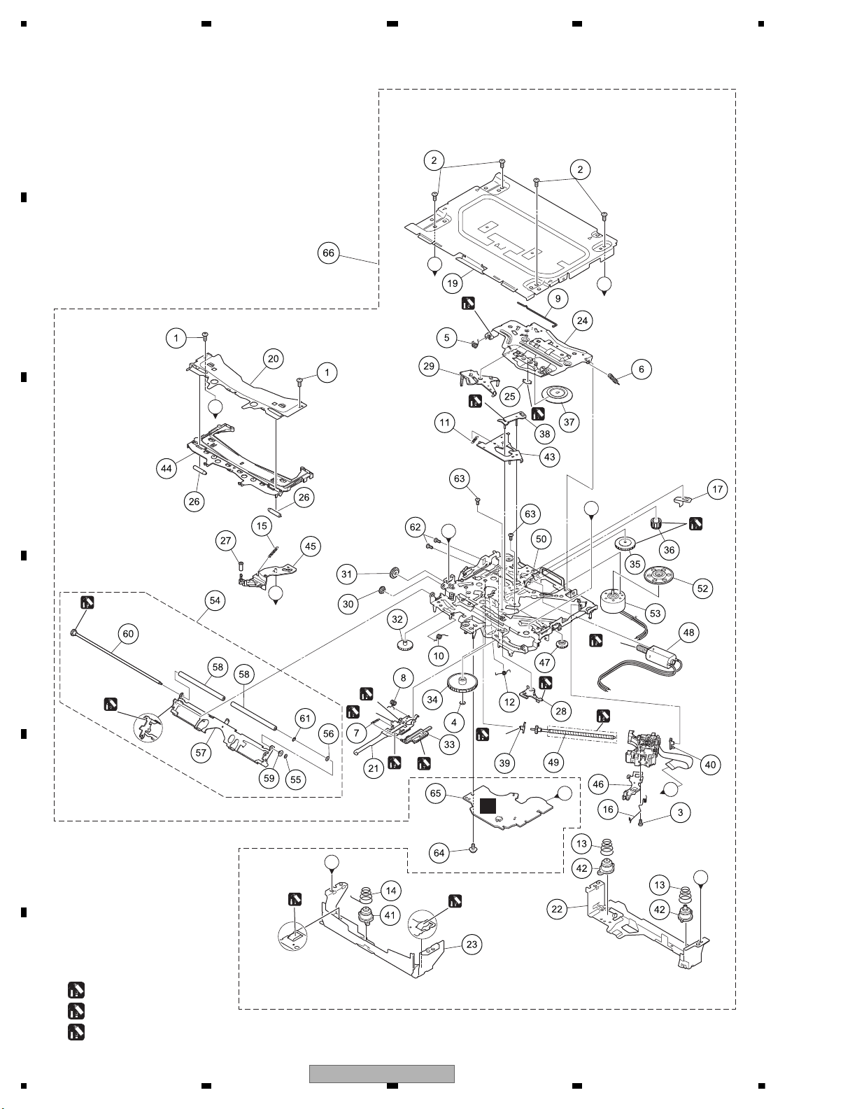
1234
1234
C
D
F
A
B
E
9.5 DVD MECHANISM MODULE (1)
A
E
A
B
B
D
C
C
E
D
C
(A)
: GEM1045
(B)
: GEM1038
(C)
: GEM1024
(A)
(A)
(A)
(C)
(C)
(C)
(A)
(A)
(A)
(NOTE)
(NOTE)
(NOTE)
(NOTE)
(B)
(A)
(A)
(C)
(C)
(C)
(C)
(NOTE) Apply grease to the whole part.
94
AVH-3400DVD/XUEW5
Page 95

5 678
56
7
8
C
D
F
A
B
E
DVD MECHANISM MODULE (1) SECTION PARTS LIST
Mark
Mark No. Description Part No.
1 Screw BSZ20P040FTC
No. Description Part No.
* 50 Chassis Unit CXE4047
2 Screw BSZ26P060FTC
3 Screw (M2 x 4) CBA1835
4 Washer CBF1038
5 Spring CBH2855
51 •••••
* 52 Support Wheel CNW2052
* 53 Spindle Motor(M2)(SPINDLE) EXM2002
54 Arm Assy CXE5027
6 Spring CBH2860
55 Washer CBF1037
7 Spring CBH3010
8 Spring CBH3011
9 Spring CBH3014
10 Spring CBH3015
56 Washer CBF1038
57 Arm CND6242
58 Roller CNW1196
59 Collar CNW2444
11 Spring CBH3016
12 Spring CBH3017
13 Spring CBH3019
14 Spring CBH3086
15 Spring CBH3095
60 Gear Unit CXC8893
61 Washer YE15FTC
62 Screw JFZ20P025FTC
63 Screw JGZ17P020FTC
64 Screw (M2 x 5) EBA1028
16 Spring CBH3096
65 DVD Core Unit YWX5032
17 Plate Spring CBL1824
18 •••••
66 Mechanism Unit(Service) CXX4549
19 Case CNB3762
20 Bracket CND4553
21 Lever CND5398
22 Bracket CND5710
23 Bracket CND6127
24 Arm CND6406
25 Sheet CNN3678
26 Roller CNW1172
27 Roller CNW1175
28 Arm CNW1177
29 Arm CNW1178
30 Gear CNW1180
31 Gear CNW1181
32 Gear CNW1183
33 Rack CNW1184
34 Gear CNW1185
35 Gear CNW1186
36 Gear CNW1187
37 Clamper CNW1190
38 Arm CNW1192
39 Holder CNW1193
40 Holder CNW1194
41 Damper CNW1197
42 Damper CNW1198
43 Arm CNW1726
44 Guide CNW2240
45 Arm CNW2241
46 Rack CNW2265
47 Gear CNW2287
48 Motor Unit(M1)(CRG(L/E)) CXC4026
49 Screw Unit CXC8894
AVH-3400DVD/XUEW5
95
Page 96
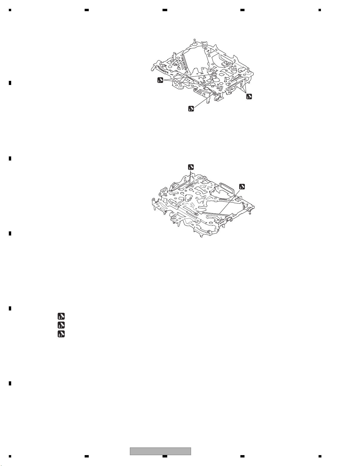
1234
1234
C
D
F
A
B
E
9.6 DVD MECHANISM MODULE (2)
(C)
(C)
(C)
(A)
(B)
(A)
: GEM1045
(B)
: GEM1038
(C)
: GEM1024
96
AVH-3400DVD/XUEW5
Page 97

5 678
56
7
8
C
D
F
A
B
E
AVH-3400DVD/XUEW5
97
Page 98
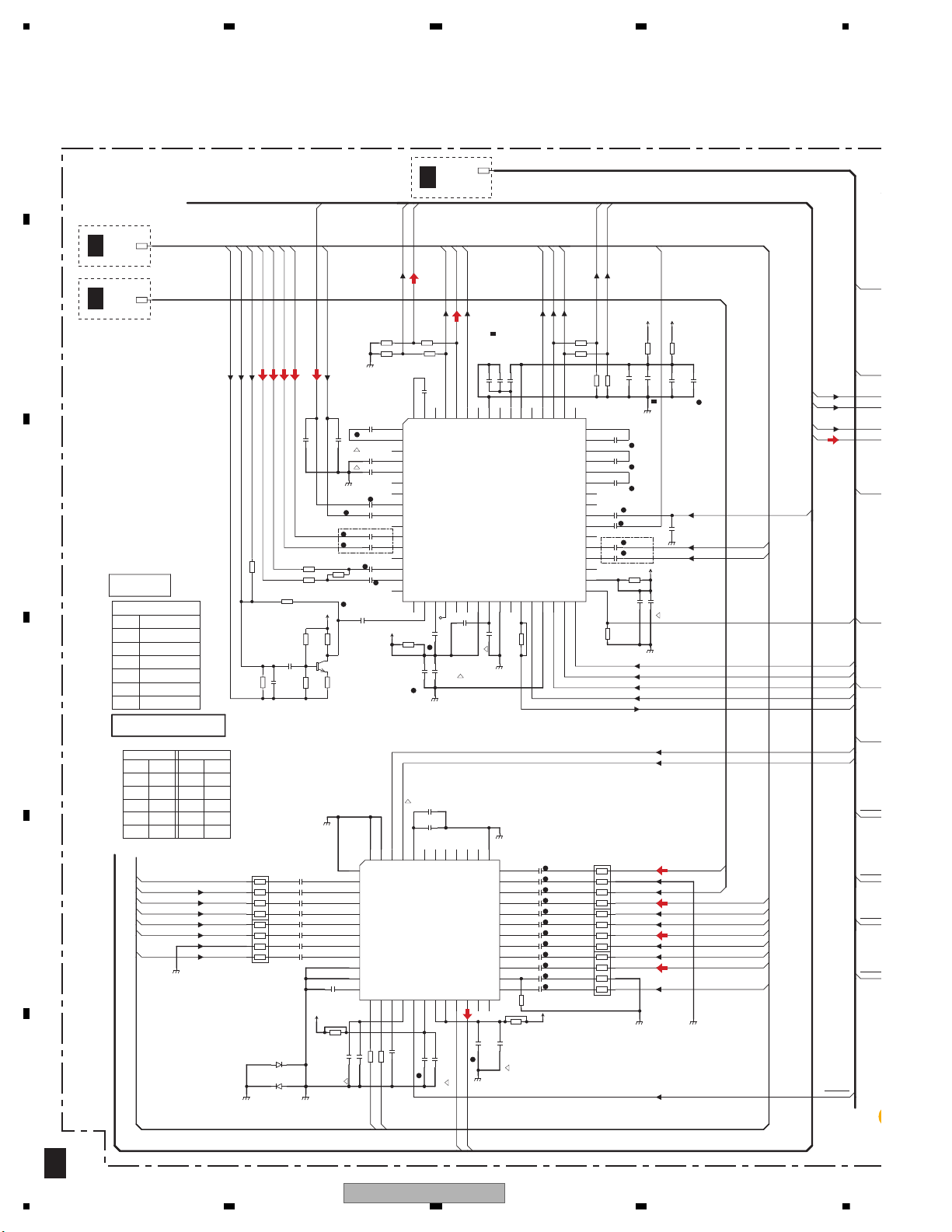
1234
1234
C
D
F
A
B
E
10. SCHEMATIC DIAGRAM
Note: When ordering service parts, be sure to refer to " EXPLODED VIEWS AND PARTS LIST" or
"ELECTRICAL PARTS LIST".
1/5
A
AUX_AGND
BUSR-
EVSDA
RCA_FR
RCA_SWR
AV_ROUT1
RCA_SWL
AVSRST
RCA_RR
AUX_VGND
RCA_RL
TUN_L
AVSDA
AV_ROUT1
BUSL-
ONSEI-
RCA_FL
BUSL+
AUX_L
AVSCL
MONVBS
EVSEL
EVSAOUT
ISENS
LS_L
RL
AV_LOUT1
LS_R
FL
ASENS
RL
AUX_V
RR
AUX_R
FR
BSENS
TUN_R
FL
AV_LOUT1
ONSEI+
BGSEN
FR
EVSACLK
RCAMU
AUX_AGND
TELMUT
RR
EVSCK
BUSR+
AMPPW
EVMUTE
BTANAL
BTANAR
AEQMICIN
AUX_L
PBSENS
LS_V
BC_VGND
BCAM_IN
AANT
VCR_GND
VCR_L
VCR_R
VCR_VGND
RCA_V
VCR_V
SYSMU
C240
NM
C251
CCG1192-A
C225
CCG1192-A
C238
NM
C252
0.1u/10
C256
0.1u/10
C266
CCG1192-A
C265
0.1u/10
C201
NM
C241
10u/35
C254
0.1u/10
C232
1u/10
C258
0.1u/10
C279
1u/10
C264
0.1u/10
C277
1u/10
C280
1u/10
C237
NM
C267
0.1u/10
C229
10p/50
C276
1u/10
C239
0.1u/10
C230
1u/10
C263
CCG1192-A
1u/10
C221
C223
CCG1321-A
C257
0.1u/10
C212
2.2u/10
CCG1218-A-T
C270
CCG1321-A
C231
1u/10
C228
10u/35
CCG1236-A-T
C281
1u/10
C278
1u/10
C224
0.47u/10
C216
1u/10
C214
0.022u/50
C259
0.1u/10
C236
NM
C226
10p/50
C234
1u/10
C269
CCG1192-A
C217
NM
C218
1u/10
C282
1u/10
C268
CCG1321-A
C219
1u/10
C242
CCG1321-A
C274
1u/10
C260
0.1u/10
NM
C211
C222
1u/10
1u/10
C233
C271
CCG1192-A
C207
NM
C213
1u/10
C275
1u/10
C255
0.1u/10
C227
CCG1192-A
C253
0.1u/10
C273
1u/10
C283
1u/10
C220
1u/10
C208
NM
C202
NM
1u/10
C235
C272
1u/10
C215
0.022u/50
D254
NM
D255
NM
GNDA
GNDA
GNDA
GNDA
GNDA
GNDV
GNDA
GNDV
GNDA
GNDV
GNDA
GNDA
TUNAGGNDA
GNDA
AK4223VQ
IC251
VIN6
1
VGND5
2
VIN5
3
VGND4
4
VIN4
5
VGND3
6
VIN3
7
VGND2
8
VIN2
9
VGND1
10
VIN1
11
VR2
12
VOUT213VOUT114VR1
15
REGV16RSTN
17
VVDD18AVDD19RVDD20ROUT221LOUT222ROUT1
23
LOUT1
24
RIN6
25
GND6
26
LIN6
27
RIN5
28
GND5
29
LIN5
30
RIN4
31
GND4
32
LIN4
33
RIN3
34
GND3
35
LIN3
36
VSS137RIN238GND239LIN240RIN141GND142LIN143VCOM
44
SDA45SCL
46
VSS2
47
VGND6
48
IC201
PML020A
Svin_RL
1
Tout_RL
2
N.C.1
3
APF_2
4
APF_1
5
N.C.2
6
IN1L
7
IN2L
8
IN3L
9
N.C.3
10
IN4L+
11
IN4L-
12
N.C.4
13
IN5L
14
IN5G
15
IN5R
16
TEST_OUT17MIC_in18DC_filter19MIC_AMP_Out20N.C.521N.C.6
22
VCC
23
Cref24GND
25
SA_TEST_OUT26SA_TEST
27
SACLK28DGND
29
CLK30DATA31STB
32
MUTE
33
DVCC
34
N.C.7
35
IN4R-
36
IN4R+
37
N.C.8
38
IN3R
39
IN2R
40
IN1R
41
N.C.9
42
Tout_pre
43
Svin_Pre
44
Tout_RR
45
Svin_RR
46
Tout_FR
47
Svin_FR
48
N.C.10
49
Front_R
50
Rear_R
51
Pre_SWR
52
N.C.11
53
VP
54
Pref
55
N.C.12
56
PGND
57
N.C.13
58
Pre_SWL
59
Rear_L
60
Front_L
61
N.C.14
62
Svin_FL63Tout_FL
64
Q201
NM
R258
100
2
1
4
3
6
5
8
7
R251
100
2
1
4
3
6
5
8
7
R252
100
2
1
4
3
6
5
8
7
R259
100
2
1
4
3
6
5
8
7
R260
100
2
1
4
3
6
5
8
7
R217
1.8k
R256
NM
R216
NM
R207
NM
R208
NM
R257
NM
R201
NM
R255
75
R220
2.7k
R202
0
R223
47k
R230
NM
R222
0
R210
5.6k
R218
1.8k
R205
2.7k
R213
NM
R212
2.7k
R253
NM
R221
NM
R204
2.7k
R214
1.8k
R211
2.7k
R203
NM
R254
75
R219
2.7k
R215
1.8k
R206
NM
R209
NM
MAO
EV12
SYS+B
SYS+B
SYS+B
SYS+B
SYS+B
SYS+B
ANA TUN BUS
ANA SYS BUS
ANA IF BUS
AUX
LS-2
VCR
E.VOL
AV SELECTOR
AUX
CH3
AUDIO CH
E. VOL IC INPUT
-
NAVI GUIDE
-
CH2
BT TEL AUDIO
CH5
CH6
CH4 CH4
CH6
CH5
3
CH1
BC
-
CH2
-
CH3
IP BUS
AV SEL
INNER BUS
6
M
-
LS-2
1
VIDEO CH
5
-
VCR
2
TUN
CH1
4
(TUN AGND)
(LS2 VGND)
-
201 - : E.Vol
101 - : PWAMP
161 - : MUTE
251 - : AV.Sel
121 - : SENS
ANA TUN BUS
10u
0.1u
10u
0.1u
10u
0.1u
10u
10u
0.1u
10u
10u
except A
2/5
A
5/5
A
4/5
A
FM/A
E.V
FM/AM(30%): -11.0 dBs(A)
FM/AM(30%): -15.0 dBs(except A)
IP BUS:+2.2 dBs
AUX:+2.2 dBs
VCR:+2.2 dBs
iPod(AUX):+1.3 dBs
USB&SD:+5.1 dBs
DVD/CD(LS2):+5.1 dBs
Navi Guide:+8.6 dBs
E.VOL Input
FM/AM(30%): -11.0 dBs(A)
FM/AM(30%): -15.0 dBs(except A)
IP BUS:+2.2 dBs
AUX:+2.2 dBs
VCR:+2.2 dBs
iPod(AUX):+1.3 dBs
USB&SD:+5.1 dBs
DVD/CD(LS2):+5.1 dBs
Navi Guide:+14.5 dBs
AV SEL Input
except A
10.1 MOTHER PCB (ANALOG BLOCK)
98
AVH-3400DVD/XUEW5
Page 99

5 678
56
7
8
C
D
F
A
B
E
1/5
A
9.RL+
8.PW.GND1
GND
17.FL+
ILM
18.PW.GND3
RL-
1.TAB
FR-
2.PW.GND2
23.FR-
14.RRIN
20.VCC3/4
13.S-GND
10.SVR
B.REM
15.RLIN
3.RR-
RR+
BGSENS
11.FLIN
7.RL-
RR-
FL+
FL-
MUTE
21.FR+
B.UP
FR+
ACC
RL+
5.RR+
16.ACGND
22.MUTE
4.STBY
12.FRIN
6.VCC1/2
24.PW.GND4
P.B.
19.FL-
25.B.REMOTE
RR+
RL-
RL-
EVSDA
FL-
RL+
AVSRST
RR+
RR-
FR-
AVSDA
FR+
AVSCL
RR-
EVSEL
FR-
EVSAOUT
ISENS
ASENS
RL
RR
FR
BSENS
RL+
FL
BGSENS
FL-
EVSACLK
RCAMUTE
FL+
FL+
TELMUTE
FR+
EVSCK
AMPPW
EVMUTE
PBSENS
AANT
SYSMUTE
100u/16
C162
C166
C125
CCG1328-A
C129
10u/35
C154
1u/10
C124
CCG1328-A
C152
CCG1321-A
C165
0.1u/50
C153
0.1u/50
C164
NM
C151
2.2u/10
CCG1218-A-T
C155
NM
C163
CCG1201-A
C101
CCG1328-A
C160
0.1u/50
C128
2.2u/10
C122
CCG1328-A
C123
CCG1328-A
C156
NM
C161
NM
C159
NM
C158
0.1u/50
C127
CCG1328-A
C121
CCG1328-A
C157
NM
C126
CCG1328-A
D101
CRG03
D122
DA2J101
D102
CRG03
D128
1SR154-400
D164
DA2J101
D129
1SR154-400
D212
CRG03
D161
NM
D211
CRG03
D127
DAN202UM
D123
DAN202UM
D163
NM
D126
DZ2J056M0
D162
NM
D125
HZU7L(C3)
D124
NM
D121
HZU7L(A1)
GNDD
GNDD
GNDD
GNDD
GNDD
GNDD
GNDD
GNDD
GNDD
GNDD
GNDA
GNDD
GNDA
GNDD
GNDD
GNDA
GNDA
GNDA
GNDA
IC101
PA2030A
TAB
1
PW-GND2
2
OUT2(-)
3
STBY
4
5
OUT2(+)
6
VCC2
7
OUT1(-)
8
PW-GND1
9
OUT1(+)
10
RIPPLE
11
IN1
12
IN2
15
IN3
16
AC-GND
17
OUT3(+)
18
PW-GND3
19
OUT3(-)
20
VCC1
21
OUT4(+)
22
MUTE
23
OUT4(-)
24
PW-GND4
25
H-SW/VOS-DET
13
PRE-GND
14
IN4
JA121
CKM1376-A
1
2
3
4
5
6
7
8
9
10
11
12
13
14
15
16
L124
CTH1221-A
L122
NM
L123
NM
L121
NM
DRC9A14E0
Q211
DRC9A14E0
Q125
DRC9A14E0
Q122
HN1C01FU(YGR)
121Q
E11B12C2
3
E2
4
5B26
C1
RN4982
Q164
E1
1
B1
2
C2
3
E2
4
5
B2
6
C1
RN4983
Q162
E1
1
B1
2
C2
3E24
5
B2
6
C1
HN1A01FU(YGR)
Q123
E11B12C2
3
E2
4
5B26
C1
Q124
NM
Q161
NM
2SB1731
Q212
R124
47k
R135
100k
R226
1.5k
R162
NM
R133
NM
R152
1k
R225
10k
R122
NM
R123
10k
R138
1k
R161
NM
R224
68k
R144
1k
R228
100
R236
4.7k
R137
47k
R200
1k
R198
NM
R130
47k
R229
47k
R136
100k
R129
4.7k
R140
15k
R143
1k
R199
NM
R163
NM
R142
1k
R134
NM
R131
10k
R128
47k
R125
22k
R132
NM
R127
10k
R121
NM
R235
10k
R139
10k
R227
68k
R126
47k
FL-
ILM
RL+
BRMT
ANT
G1
FR+
G3
RR-
G2
ACC
BGS
PBK
FL+
RL-
FR-
TMT
RR+
BSN
OMT
BUP_1
SYS+B
SYS+B
SYS+B
VDD33
BUP_1
VDD33
Q163
RN1903
1
2
3
4
5
6
8.4V
14.4V
ISENS
14.4V
1608
CHIP SIZE LEGEND
2125
AMP
3216
ASENS
8.3V
TELMUTE
AMPMUTE
BGSENS
(CCG1236-A)
OFFMUTE
8.4V
PBSENS
3.4V
BSENS
A ANT
(CTF1547)
(BTH1101)
(BTH1101)
3300u/16
0.47u
0.47u
0.47u
0.47u
0.47u
0.47u
0.47u
0.47u
4.7u
0.1u
600 uH
NM
MOTHER PCB
(ANALOG BLOCK)
1/5
A
Symbol indicates a resistor.
No differentiation is made between chip resistors and
discrete resistors.
NOTE :
Symbol indicates a capacitor.
No differentiation is made between chip capacitors and
discrete capacitors.
NM : No Mount
SERVICE UNIT(MOTHER I/F)
Consists of
MOTHER PCB
IF PCB
: The power supply is shown with the marked box.
POWER SUPPLY
FM/AM(30%):+23.7 dBs(A)
FM/AM(30%):+19.7 dBs(except A)
IP BUS:+35.9 dBs
AUX:+35.9 dBs
VCR:+35.9 dBs
iPod(AUX):+36.0 dBs
USB&SD:+35.8 dBs
DVD/CD(LS2):+35.8 dBs
Navi Guide:+14.1 dBs
FM/AM(30%):+2.1 dBs(A)
FM/AM(30%): -1.9 dBs(except A)
IP BUS:+14.3 dBs
AUX:+14.3 dBs
VCR:+14.3 dBs
iPod(AUX):+14.4 dBs
USB&SD:+14.2 dBs
DVD/CD(LS2):+14.2 dBs
Navi Guide: -7.5 dBs
E.VOL Output
A
B
C
D
E
F
AVH-3400DVD/XUEW5
AVH-P3400DVD/XUUW5
AVH-P3450DVD/XURC
AVH-P3450DVD/XURD
AVH-P3450DVD/XURI
AVH-P3490DVD/XUID
FUSE
YEK5001
10 A
>
AVH-3400DVD/XUEW5
99
Page 100
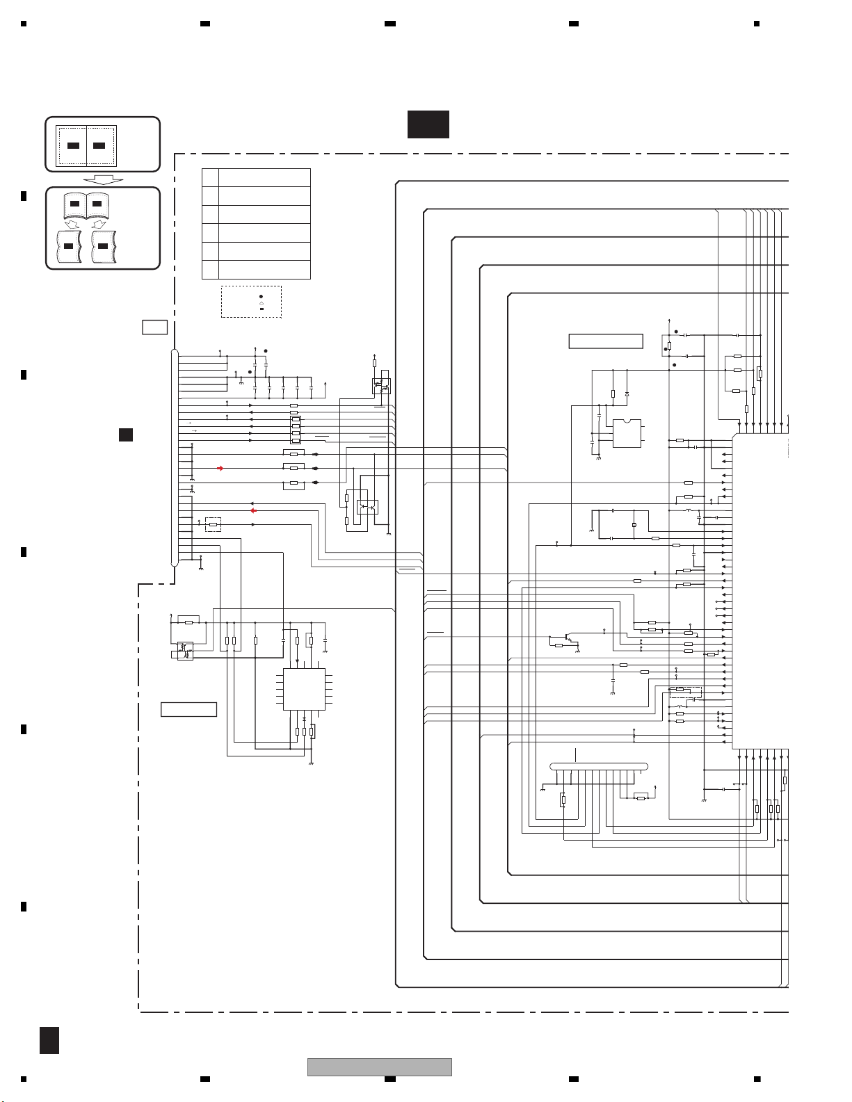
1234
1234
C
D
F
A
B
E
10.2 MOTHER PCB (SYSTEM BLOCK) (GUIDE PAGE)
A-a
2/5
A-a A-b
A-a
A-b
A-b
A-a
Large size
SCH diagram
Guide page
Detailed page
2/5
A
SYS+B
VD5
VD8
IP_TO_S
PNLADX
AMUTE
PNLADY
D+
LS_L
TEMPSEN
KDT1
S_TO_IP
BEEP
XRST
PNLADCRT
LS_R
STANBY
SPDIF
SYSTOLS
IRQPW
D-
KDT0
LSTOSYS
POS
REMIN
EVMUTE
LS_V
STANBY
B_PWM
AANT
RGBARI
GUIDEON
S_TO_N
N_TO_S
ASENBO
SYSPW
AMPPW
USBCNT
SYSTOLS
LSTOSYS
FLG
VDCNT5
NM
CN601
GNDD
1
DCK2GNDD3RESET
4
FLMD0
5
DMS6DRST
7
DDI
8
DDO9VDD33
10
VDD3311GNDD
12
NC
13
CN701
VD8 1
VD8
2
VD8
3
PGND
4
PGND
5
PGND
6
VD5
7
AMUTE
8
XRESET
9
IRQPWR
10
HSTCMD
11
SLVSTS
12
STANBY 13
AGND
14
ANA_R_OUT
15
AGND
16
ANA_L_OUT
17
AGND 18
MOVBS 19
VIDEO_GND
20
WAKEUP
21
D-
22
D+
23
DGND
24
IECOUT
25
DGND
26
SCL 27
SDA
28
CPRST
29
CPRDY
30
C604
CCG1318-A
C601
1u/10
C620
NM
C602
22p/50
C701
CCG1321-A
C609
CCG1201-A
C751
0.1u/10
C617
NM
C603
22p/50
C605
CCG1321-A
C608
0.1u/10
C752
0.1u/10
C610
0.1u/10
C606
0.1u/10
C607
0.1u/10
D601
DA2J101
L602
CTF1787-A
L601
CTF1787-A
GNDA
GNDD
GNDD
GNDD
GNDA
GNDV
GNDD
GNDD
GNDD
GNDD
GNDD
GNDD
GNDD
341S2162
IC751
NC1
1
MODE1
2
NC2
3
nRESET
4
VCC
5
NC3
6
NC4
7
NC5
8
NC6
9
NC7
10
VSS
11
I2C_SCL
12
I2C_SDA
13
MODE0
14
NC8
15
NC9
16
NC10
17
NC11
18
NC12
19
NC13
20
IC601
S-80829CNMC-B8O
OUT
1
VDD
2
VSS3NC1
4
5
NC2
AVREF0
1
AVSS
2
NC
3
NC
4
AVREF1
5
NC
6
REMIN
7
NC
8
SELFPRG
9
FLMD0
10
VDD
11
REGC
12
VSS
13
X1
14
X2
15
RESET
16
XT1
17
XT2
18
NC
19
/STANBY
20
EVMUTE
21
DRST
22
NC
23
NC
24
NC
25
NC
26
NC
27
/GUIDEON
28
/RGBARI
29
TXNAVI
30
RXNAVI
31
AANT
32
B_PWM
33
BEEP
34
ASENBO
35
TXIP
36
RXIP
37
EVSS
38
EVDD
39
TSI
40
TCK
41
TSO
42
SYSPW
43
AMPPW
44
/USBFLG
45
USBCNT
46
DDI
47
DDO
48
DCK49DMS
50
LSTOSYS
51
SYSTOLS
BTTESTMD
PNLADCRT
170
PNLADY
171
PNLADX
172
TEMPSEN
173
KDT1
174
KDT0
175
POS
176
HN1C01FU(YGR)
Q701
E11B12C2
3
E2
4
5B26
C1
RN4982
Q702
E11B12C2
3
E2
4
5B26
C1
NM
Q751
E1
1
B1
2
C2
3E24
5
B2
6
C1
Q603
LSCR523UB
R704
220
2
1
4
3
6
5
8
7
R709
NM
R711
4.7k
R615
NM
R682
R701
100
R651
470
R627
NM
R653
47k
R703
470
R641
1k
R654
NM
R639
470
R649
4.7k
R751
NM
R645
4.7k
R692
100k
R623
10
R614
NM
R755
1k
R619
100k
R657
220
R655
47k
R752
10k
R656
47k
R644
4.7k
R620
NM
R647
47k
R640
470
R759
NM
R621
1k
R646
100
R638
47k
R710
NM
R713
1k
R643
4.7k
R642
47k
R756
100
R753
10k
R754
10k
R612
47k
R650
4.7k
R652
470
R757
100
R628
NM
R648
NM
R712
4.7k
R702
1k
R708
NM
R631
100k
R758
NM
R635
47k
R603
NM
BT1
VD8
PGD
MAG
MVG
SPD
MDG
FMD0
AMT
NC24
NC25
NC26
TSI
TCK
TSO
IRQ
RST
STB
GDON
RGBA
STN
NTS
BEP
ASBO
SPW
APW
UFLG
UCNT
LTS
STL
VDD33
VDD33
SWVDD
X601
CSS1772-A
C702
CCG1192-A
C703
CCG1192-A
C704
CCG1192-A
C600
NM
C641
1000p/16
C705
CCG1321-A
C706
NM
C707
CCG1322-A
SYS PWR BUS
S LS1TX
SYS ANA BUS
SYS TUN BUS
SYS ANA BUS
8.3V
LS1
SRX
PGND
AMUTE
INNER BUS
5.1V
INNER BUS
DGND
SYS PWR BUS
/XRST
DGND
8.0V
SYS TUN BUS
IRQPW
LS_LOUT
SYSTEM MICOM
IPOD CP IC
1608
PGND
LS2
3.93216MHz
3216
2125
SYS IF BUS
CHIP SIZE LEGEND
STNBY
SYS IF BUS
LS_ROUT
CKS6025-A
0.1u
2.2u
0.1u
10u
10u
10u
10000p
0.1u
4.7u
except A
except A
C
CN1952
A
B
C
D
E
F
AVH-3400DVD/XUEW5
AVH-P3400DVD/XUUW5
AVH-P3450DVD/XURC
AVH-P3450DVD/XURD
AVH-P3450DVD/XURI
AVH-P3490DVD/XUID
DVD/CD(LS2):+5.1 dBs
100
AVH-3400DVD/XUEW5
 Loading...