


 Loading...
Obstetrical Care
S E R V I C E G U I D E
Avalon Fetal Monitor
FM40 / FM50
F E T A L M O N I T O R I N G
Printed in Germany
*M2703-9000C*
Part Number M2705-9000A
451261025951
S

M2705-9000A
Table of Contents
1 |
Introduction |
1 |
|
Who Should Read This Guide |
1 |
|
What to Do Next |
1 |
|
Repair Strategy |
2 |
|
Manufacturer’s Information |
2 |
|
Passwords |
3 |
|
Warnings and Cautions |
3 |
2 |
Site Preparation |
5 |
|
|
|
|
Introduction |
5 |
|
Site Planning |
5 |
|
Roles and Responsibilities |
5 |
|
Site Preparation Responsibilities |
5 |
|
Procedures for Local Staff |
6 |
|
Procedures for Philips Personnel |
7 |
|
Site Requirements |
7 |
|
Space Requirements |
7 |
|
Environmental Requirements |
7 |
|
Safety Requirements (Customer or Philips) |
8 |
|
Electrical Requirements (Customer or Philips) |
8 |
|
Connecting Non-Medical Devices |
8 |
|
Cabling Options and Requirements for Connection to OB TraceVue |
9 |
|
Mounting Options |
9 |
|
PS/2 Input Devices |
10 |
|
Displays and Touch Devices |
10 |
|
M8031B: 15” TFT Medical Grade Touch Display |
10 |
|
M8033C: 17” TFT Medical Grade Touch Display |
10 |
|
Video Cables for Remote Displays |
11 |
3 |
Installation Instructions |
13 |
|
|
|
|
Initial Inspection |
13 |
|
Visual Inspection |
13 |
|
Electrical Inspection |
13 |
|
Claims for Damage |
13 |
|
Repackaging for Shipment or Storage |
14 |
|
Mounting Instructions |
14 |
|
Line Voltage Selection |
14 |
|
Rear View |
15 |
|
Connecting the Monitor to AC Mains |
15 |
i

|
Connecting the Monitor to Non-Medical Devices |
15 |
|
Connecting a Remote Display via the MIB/RS232 Interface |
16 |
|
Installing a Remote Display |
16 |
|
Mounting Remote Displays |
16 |
|
Before Using the Monitor |
16 |
|
Checking and Setting Line Frequency |
17 |
|
Checking/Setting Paper Scale |
17 |
|
Checking/Setting Paper Speed |
18 |
|
Configuring the Equipment Label |
18 |
|
Configuring SmartKeys |
18 |
|
PS/2 Keyboard/Mouse |
18 |
4 |
Theory of Operation |
19 |
|
|
|
|
Monitor Hardware Overview |
19 |
|
Power Supply |
20 |
|
Fetal Sensor Connector Block |
20 |
|
API (All Peripheral Interfaces) Board |
20 |
|
Main CPU Board |
21 |
|
Fetal Recorder (Thermal Printer Unit) |
21 |
|
Thermal Line Printhead (TLPH) |
21 |
|
Paper Sensor |
21 |
|
Stepper Motor |
21 |
|
LCD Display and Touchscreen |
21 |
|
Noninvasive Blood Pressure Assembly |
21 |
|
SpO2 Assembly |
21 |
|
Input/Output Interface Boards |
22 |
|
Transducer Hardware Overview |
22 |
|
Transducer Types |
23 |
|
Functional Description of the Transducer CPU |
23 |
|
CPU (Micro Controller) |
23 |
|
Analog-to-Digital Converter |
23 |
|
Communication Transceiver (CAN Bus Driver) |
23 |
|
EEPROM |
23 |
|
Toco Transducer Frontend |
23 |
|
Ultrasound Transducer Frontend |
23 |
|
Toco+ Transducer Frontends |
24 |
|
Toco Frontend |
24 |
|
IUP Frontend |
24 |
|
ECG Frontend |
24 |
|
Patient Module Frontends |
24 |
|
Avalon CTS Interface Cable (TMIF) |
24 |
5 |
Rear Interfaces |
25 |
|
|
|
|
LAN / RS232 Interface |
25 |
|
Dual PS/2 Interface |
26 |
|
MIB / RS232 Interface |
26 |
ii

Telemetry Interface |
26 |
VGA Video Out |
26 |
6 Connection to a Network |
27 |
|
|
Network Infrastructure Requirements |
27 |
Connection Indication Messages |
27 |
Broadcast |
27 |
Unicast |
28 |
Equipment Label and OB TraceVue Fetal Monitor Domain Name |
28 |
7 Testing and Maintenance |
29 |
|
|
Recommended Frequency |
29 |
When to Perform Test Blocks |
30 |
Preventive Maintenance Procedures |
31 |
Noninvasive Blood Pressure Measurement Calibration |
31 |
Fetal Recorder Maintenance |
31 |
Testing Sequence |
31 |
Visual Inspection |
32 |
Before Each Use |
32 |
After Each Service, Maintenance or Repair Event |
32 |
Safety Tests |
32 |
Warnings, Cautions, and Safety Precautions |
32 |
Safety Test Procedures |
33 |
S(1): Protective Earth Resistance Test |
34 |
S(2): Equipment Leakage Current Test - Normal Condition |
34 |
S(3): Equipment Leakage Current Test - Single Fault Condition |
35 |
S(4): Applied Part Leakage Current - Mains on Applied Part |
35 |
System Test |
37 |
What is a Medical Electrical System? |
37 |
General Requirements for a System |
37 |
System Example |
37 |
Performance Assurance Tests |
38 |
Noninvasive Blood Pressure Performance Tests |
38 |
Accuracy Test |
38 |
Leakage Test |
39 |
Linearity Test |
39 |
Valve Test |
40 |
Expected Test Results |
40 |
SpO2 Performance Test |
40 |
Expected Test Results |
40 |
Measurement Validation |
40 |
Reporting of Test Results |
41 |
Carrying Out and Reporting Tests |
42 |
Other Regular Tests |
43 |
Transducers and Patient Modules: Functional Tests |
43 |
Ultrasound Transducer Electrical Check |
43 |
iii

|
Toco Transducer Electrical Check |
44 |
|
Testing the Patient Module (M2738A)/Toco+ Transducer (M2735A): DECG Mode |
45 |
|
Testing the Patient Module (M2738A)/Toco+ Transducer (M2735A): MECG Mode |
46 |
|
Testing the Patient Module (M2738A)/Toco+ Transducer (M2735A): IUP Mode |
47 |
|
Touchscreen Calibration |
48 |
|
Disabling/Enabling Touch Operation |
49 |
|
Checking the Fetal Recorder Offset |
49 |
|
Setting the Fetal Recorder Offset |
49 |
|
Fetal Recorder Selftest Report |
50 |
8 |
Troubleshooting |
53 |
|
|
|
|
Who Should Perform Repairs |
53 |
|
Replacement Level Supported |
53 |
|
Checking Revision Information |
53 |
|
Trace Header |
54 |
|
Hardware Revision Check |
54 |
|
Software Revision Check |
55 |
|
Obtaining Replacement Parts |
55 |
|
Troubleshooting Guide |
55 |
|
Checks for Obvious Problems |
55 |
|
Checks Before Opening the Instrument |
55 |
|
Checks with the Instrument Switched On, AC connected |
55 |
|
Individual Parameter INOPs |
56 |
|
Initial Instrument Boot Phase |
57 |
|
Troubleshooting Tables |
57 |
|
How to Use the Troubleshooting Tables |
57 |
|
Boot Phase Failures |
58 |
|
Screen is Blank |
58 |
|
Touchscreen not Functioning |
59 |
|
General Monitor INOP Messages |
60 |
|
Network Status Icons |
61 |
|
Alarm Tones |
61 |
|
Alarm Behavior |
61 |
|
Fetal Recorder |
61 |
|
LAN / RS232 |
64 |
|
Keyboard/Mouse not Functioning |
64 |
|
Remote Touch Display not Responding (MIB/RS232) |
65 |
|
No Video on Remote Display |
65 |
|
Transducers |
66 |
|
Status Log |
67 |
|
Troubleshooting with the Support Tool |
68 |
|
Troubleshooting the Individual Measurements or Applications |
68 |
9 |
Parts |
71 |
|
|
|
|
Monitor |
71 |
|
Transducers |
73 |
iv

Patient Modules |
74 |
Interface Cables |
74 |
Assemblies and Kits |
75 |
Front Bezel Assembly |
75 |
Main CPU Board |
76 |
API Board Kit |
76 |
Noninvasive Blood Pressure Assembly |
76 |
Recorder Assembly |
77 |
Thermal Line Printhead (TLPH) |
77 |
Loudspeaker Assembly |
77 |
Top Cover |
78 |
AC/DC Power Supply |
78 |
SpO2 Board |
78 |
Interface Boards |
79 |
Fetal Sensor Socket Connector Kit |
79 |
Rear (Telemetry) Connector Kit |
79 |
SpO2 Connector Kit |
80 |
Noninvasive Blood Pressure (NBP) Connector Kit |
80 |
Camlock Kit |
80 |
FM Small Parts Kit - Plastic Parts and Labels |
81 |
FM Small Parts Kit - Screws and Cables |
83 |
Transducer Cable Assembly |
84 |
Belt Button Kit |
84 |
10 Disassembly and Reassembly |
85 |
|
|
Introduction |
85 |
How to Use this Chapter |
85 |
Tools Required |
86 |
Screws Used |
86 |
Screw Map |
87 |
Serial Numbers |
87 |
Removing the Top Cover |
88 |
Refitting the Top Cover |
89 |
Removing the Power Supply Assembly |
90 |
Refitting the Power Supply Assembly |
91 |
Removing the Loudspeaker Assembly |
91 |
Refitting the Loudspeaker Assembly |
92 |
Removing the Noninvasive Blood Pressure Assembly |
92 |
Refitting the Noninvasive Blood Pressure Assembly |
93 |
Removing the SpO2 Assembly |
94 |
Refitting the SpO2 Assembly |
94 |
Removing the Interface Boards |
95 |
Refitting the Interface Boards |
96 |
Removing the Main CPU Board |
96 |
Refitting the Main CPU Board |
98 |
Removing the Front Bezel Assembly |
99 |
v

Refitting the Front Bezel Assembly |
101 |
Removing the Telemetry Socket Connector Block |
102 |
Refitting the Telemetry Socket Connector Block |
102 |
Removing the Sensor Socket Connector Block |
103 |
Refitting the Sensor Socket Connector Block Assembly |
104 |
Removing the API Board |
105 |
Refitting the API Board |
107 |
Removing the Recorder Assembly |
107 |
Refitting the Recorder Assembly |
110 |
Removing the Thermal Line Printhead (TLPH) |
111 |
Refitting the TLPH |
112 |
Transducer Disassembly/Reassembly |
113 |
Exchanging the Transducer Cable |
113 |
Exchanging the Transducer Belt Button |
115 |
11 Upgrades |
117 |
|
|
FM40/50 Upgrade Options |
117 |
Installing Upgrade Options |
118 |
Option C73 |
118 |
Options J22 and J70 |
118 |
Software and Firmware Upgrades |
118 |
12 Understanding Configuration |
119 |
|
|
What is Configuration Mode? |
119 |
Understanding Settings |
120 |
Entering and Leaving Configuration Mode |
120 |
Storing Changes in the User Defaults |
121 |
Loading the Factory Default |
122 |
Loading the User Defaults |
122 |
Loading Configurations Using the Support Tool |
123 |
About Configuration Files (.cfg) |
123 |
Selecting the Correct Configuration |
123 |
13 Configuration Settings Appendix |
125 |
|
|
Documenting Monitor Configurations |
125 |
Using the Configuration Tables |
125 |
Configuration Table Example |
126 |
Understanding Configuration Implications |
126 |
Measurement-Related Settings |
127 |
Color Configuration |
127 |
Configuring FHR (Ultrasound) |
127 |
FHR Configuration Implications |
127 |
Configuring Toco |
128 |
Configuring IUP |
128 |
Configuring DFHR (DECG) |
128 |
DFHR Configuration Implications |
128 |
vi

Configuring MHR (ECG)/Pulse |
129 |
ECG/Pulse Configuration Implications |
129 |
Configuring SpO2 |
130 |
SpO2 Configuration Implications |
130 |
Configuring Noninvasive Blood Pressure (NBP) |
132 |
NBP Configuration Implications |
132 |
Monitor-Related Settings |
133 |
Configuring Alarms |
133 |
Alarm Settings Configuration Implications |
133 |
Configuring the NST Timer |
134 |
NST Timer Configuration Implications |
134 |
Configuring Fetal Recorder Settings |
135 |
Recorder Configuration Implications |
135 |
Configuring User Interface Settings |
136 |
User Interface Configuration Implications |
136 |
Configuring Global SmartKeys |
138 |
Global SmartKeys Configuration Implications |
138 |
Changing the Selection and Sequence of Global SmartKeys |
138 |
Hardware Settings |
139 |
Global Settings |
139 |
Global Settings Configuration Implications |
139 |
vii

viii
1
Introduction
This Service Guide contains technical details for the Avalon FM40 and FM50 Fetal/Maternal Monitors. It provides a technical foundation to support effective troubleshooting and repair. It is not a comprehensive, in-depth explanation of the product architecture or technical implementation. It offers enough information on the functions and operations of the monitoring systems so that engineers who repair them are better able to understand how they work. It covers the physiological measurements and the monitor hardware that acquires and displays them.
The Avalon FM40/FM50 Fetal Monitor Service Guide supplements the maintenance and troubleshooting procedures, carried out by the operator, that are described in the Instructions for Use. Refer to the Instructions for Use for maintenance and troubleshooting procedures that may be performed during normal operation.
Only qualified service personnel should attempt to install the system, disassemble the monitor, remove or replace any internal assemblies, or replace the transducer cable or belt buttons.
Who Should Read This Guide
This guide is for biomedical engineers or technicians responsible for troubleshooting, repairing, and maintaining Philips’ Avalon fetal monitors.
You must:
•understand English
•be familiar with standard medical equipment installation procedures
•be familiar with current conventional technical terms as used throughout this guide
What to Do Next
Familiarize yourself with the contents of this guide and the Instructions for Use before attempting to service or repair the system.
1

1 Introduction |
Repair Strategy |
Repair Strategy
The Service Support Tool software helps you to determine whether a fault is a hardware or software problem. The main replaceable parts are:
•unit exchange for the transducers
•replacement of
–the top cover
–the power supply assembly
–the loudspeaker assembly
–the noninvasive blood pressure assembly
–the SpO2 assembly
–the interface boards (RS232/LAN, dual PS/2 and MIB/RS232)
–the main CPU board
–the front bezel assembly
–the telemetry socket connector block
–the sensor socket connector block
–the API board
–the recorder assembly
–the thermal line printhead (TLPH)
–the transducer cable
–the transducer belt button
See Chapter 9, “Parts” for part numbers, and Chapter 10, “Disassembly and Reassembly” for repair details.
Repair or replacement of individual components on the boards is not supported, and should never be attempted.
For tests that you are required to perform after repairs, refer to “When to Perform Test Blocks” on page 30.
Manufacturer’s Information
© Copyright 2003 - 2008. Koninklijke Philips Electronics N.V.
All Rights Reserved.
Philips Medizin Systeme Böblingen GmbH
Hewlett-Packard-Str. 2
71034 Böblingen, Germany
2

Passwords |
1 Introduction |
Passwords
In order to access different modes within the monitor a password may be required. The passwords are listed below.
Monitoring Mode: No password required
Configuration Mode: 71034
Demo Mode: 14432
Service Mode: 1345
Refer to Chapter 12, “Understanding Configuration” before making any changes to the monitor configuration.
Warnings and Cautions
In this guide:
•A warning alerts you to a potential serious outcome, adverse event or safety hazard. Failure to observe a warning may result in death or serious injury to the user or patient.
•A caution alerts you where special care is necessary for the safe and effective use of the product. Failure to observe a caution may result in minor or moderate personal injury or damage to the product or other property, and possibly in a remote risk of more serious injury.
3

1 Introduction |
Warnings and Cautions |
4

2
Site Preparation
Introduction
This section describes the procedures you should follow to plan and prepare a site for an Avalon FM40/FM50 fetal monitor installation.
•Site planning.
•Roles and responsibilities for local and Philips personnel.
Site Planning
The careful planning of the site for the FM40/FM50 monitor is essential for its safe and efficient operation. A consulting schedule should be established between the Customer and Philips Sales and Support Representatives, to ensure that all preparations are completed when the system is delivered.
The site planning phases prior to equipment installation are:
Location: Planning the location of the various system components.
Environment: Confirming and correcting, as necessary, the environment of the proposed installation site(s).
System Capabilities: Explaining the possibilities for system expansion.
Mounting: Referencing the mounting hardware information website for the listing of suitable mounting hardware recommended for use with the various system components, and all details on the available mounts and accessories.
Cabling: Identifying the requirements for the cabling, conduiting and faceplates for connecting the various system components.
Roles and Responsibilities
This section describes the procedures necessary to prepare a site for a system installation. The procedures are grouped into two parts: procedures that local staff or contractors are responsible for, and procedures that Philips personnel are responsible for.
Site Preparation Responsibilities
Local Staff
•Ensure that all safety, environmental and power requirements are met.
•Provide power outlets.
•Prepare mounts, and consult Philips for detailed mounting requirements.
5

2 Site Preparation |
Introduction |
• Pull cables, install conduit, install wallboxes.
Philips Personnel
•Provide the customer with the safety, environmental and power requirements.
•Assemble mounts, as necessary.
•Provide requirements for cabling.
Procedures for Local Staff
The following tasks must be completed before the procedures for Philips personnel may be started.
•Providing Power Outlets
Provide a power outlet in the vicinity (1 m or 3 ft) or any peripheral equipment.
WARNING Only the power cables provided with the system may be used. For reasons of safety, power (mains) extension cables or adapters shall not be used.
•Preparing Mounts
Where ceiling, wall, or shelf mounts are required for mounting the equipment, the customer is responsible for the following:
–Providing and installing all hardware which is required to install the mounting hardware supplied by Philips as detailed in the installation notes.
–Making sure that all ceilings, walls, and mounting rails that supports mounting hardware are suitable for their proposed load.
WARNING It is the customer's responsibility to have the attachment of the mounting hardware to the ceiling, wall, or mounting rail and the construction of the ceiling, wall, or mounting rail evaluated for structural integrity and compliance with all local, state and any other required codes by a registered, professional, structural and/or mechanical engineer.
Although considerable effort has been made to ensure the safety of the ceiling mount installation and or mounting guidelines, it is to be understood that the installation itself is beyond the control of Philips Medical Systems. Accordingly, Philips Medical Systems will not be responsible for the failure of any such installation.
•Providing Conduit
–Providing conduit and/or trunking of a sufficient cross-sectional area for the planned cables and possible future expansion (for additional components or systems).
–Providing and/or installing suitable wall boxes to accommodate the faceplates.
•Pulling Cables
WARNING NEVER run power cables through the same conduit or trunking used for system cables.
• Installing Wall Boxes
6

Site Requirements |
2 Site Preparation |
It is the customer's responsibility to provide and install wallboxes to house faceplates. The customer must notify the Philips installation coordinator of which size is to be used.
Procedures for Philips Personnel
Before you begin the procedures in the installation sections, ensure that the customer has completed all necessary preparations outlined in the previous section, “Procedures for Local Staff.”
Site Requirements
The site requirements are listed in this section.
Space Requirements
The situating of the monitor should be planned such that the nursing staff are able to monitor the patient with relative ease, with all patient connectors and controls readily available and the displays clearly visible. The location should also allow access to service personnel without excessive disruption and should have sufficient clearance all round to allow air circulation.
Dimensions and weight:
Monitor:
Size (W x H x D): 420 x 172 x 370 mm (16.5 x 6.8 x 14.6 in)
Weight; < 9.0 kg (19.8 lb)
Transducer:
Size (diameter): 83 mm (3.27 in)
Weight (without cable): 190g (6.7 oz.)
Environmental Requirements
The environment where the FM40/FM50 monitor will be used should be reasonably free from vibration, dust and corrosive or explosive gases. The ambient operating and storage conditions for the FM40/FM50 monitor must be observed. If these conditions are not met, the accuracy of the system will be affected and damage can occur.
.
Monitor (M2704A/M2705A)
Interface Cable for Avalon CTS (M2731-60001/M2732-60001)
Temperature Range |
Operating |
0°C to 45°C (32°F to 113°F) |
|
Storage |
-20°C to 60°C (-4°F to 140°F) |
Humidity Range |
Operating |
<95% relative humidity @ 40°C/104°F |
|
Storage |
<90% relative humidity @ 60°C/140°F |
Altitude Range |
Operating |
-500 to 3000 m/-1640 to 9840 ft. |
|
Storage |
-500 to 13100 m/-1640 to 43000 ft. |
|
|
|
Transducers (M2734A/M2735A/M2736A/M2738A)
Temperature Range |
Operating |
0°C to 40°C (32°F to 104°F) |
|
Storage |
-20°C to 60°C (-4°F to 140°F) |
|
|
|
7

2 Site Preparation |
Site Requirements |
Transducers (M2734A/M2735A/M2736A/M2738A)
Humidity Range |
Operating |
<95% relative humidity @ 40°C/104°F |
|
Storage |
<90% relative humidity @ 60°C/140°F |
Altitude Range |
Operating |
-500 to 3000 m/-1640 to 9840 ft. |
|
Storage |
-500 to 13100 m/-1640 to 43000 ft. |
|
|
|
SpO2 Sensors
Operating Temperature Range |
0°C to 37°C (32°F to 98.6°F) |
|
|
Safety Requirements (Customer or Philips)
The monitor is an electrical Class I device in which protection against electric shock does not rely on basic insulation only, but which includes an additional safety precaution, in that means are provided for the connection of the equipment to a protective earth conductor in the fixed wiring installation in such a way that accessible metal parts cannot become live in the event of a failure of the basic insulation.
WARNING • Always use the supplied power cord with the earthed mains plug to connect the monitor to an earthed AC mains socket. Never adapt the mains plug from the power supply to fit an unearthed AC mains socket.
•Do not use additional AC mains extension cords or multiple portable socket-outlets. If a multiple portable socket-outlet without an approved separating transformer is used, the interruption of its protective earthing may result in equipment leakage currents equal to the sum of the individual earth leakage currents, so exceeding allowable limits.
Electrical Requirements (Customer or Philips)
Line Voltage Connection
The FM40/FM50 monitor uses < 60 W.
Line Voltage: the FM20/FM30 monitor may be operated on ac line voltage ranges of 100 to 240V (50/60 Hz).
Connecting Non-Medical Devices
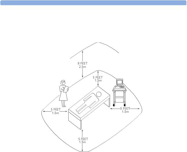
The standard IEC/EN 60601-1-1 applies to any combination of devices, where at least one is a medical device. Therefore IEC/EN 60601-1-1 must still be met after all devices are connected.
WARNING • Do not use a device in the patient vicinity if it does not comply with IEC/EN 60601-1. The whole installation, including devices outside of the patient vicinity, must comply with IEC/EN 60601-1-1. Any non-medical device, including a PC running an OB TraceVue system, placed and operated in the patient’s vicinity must be powered via a separating transformer (compliant with IEC/EN 60601- 1-1) that ensures mechanical fixing of the power cords and covering of any unused power outlets.
• Do not connect any devices that are not supported as part of a system.
8
Site Requirements |
2 Site Preparation |
Whenever you combine equipment to form a system, for example, connecting the monitor to an OB TraceVue system, perform a system test according to IEC/EN 60601-1-1 (see “System Test” on page 38).
Figure 1 Equipment Location in the Patient Vicinity
Cabling Options and Requirements for Connection to OB TraceVue
For cabling options and requirements for connection to an OB TraceVue system, refer to the OB
TraceVue Site Preparation Guide and the OB TraceVue Service Guide.
Mounting Options
See “Mounting Hardware” on page 61 for a list of mounting options. Refer to “Mounting Instructions” on page 12, or contact your local Philips representative for advice on mounting the monitor.
9

2 Site Preparation |
Site Requirements |
PS/2 Input Devices
The following table describes the input devices which can be connected to the monitor via the optional PS/2 interface.
Product Option |
Part Number |
12NC Part |
Description |
Number |
|
Number |
|
|
|
|
|
M8024A #A01 |
862454 |
989803124741 |
Slimline Keyboard with integrated Trackball |
M8024A #B01 |
M4046-60104 |
451261000661 |
Optical Mouse USB / PS/2 |
M8024A #C01 |
M4046-60103 |
451261000651 |
Wired Track Ball USB / PS2 |
M8024A #C02 |
M4046-60105 |
451261000671 |
Wireless Track Ball |
M8024A #C03 |
M4046-60106 |
451261000681 |
Wired off table Track Mouse |
|
|
|
|
Displays and Touch Devices
The following two tables describe the remote displays that can be connected to the monitor’s video output connector.
For touch operation, the MIB/RS232 interface is required. See “Connecting a Remote Display via the MIB/RS232 Interface” on page 16.
M8031B: 15” TFT Medical Grade Touch Display
Product Number |
Part Number |
12NC Part |
Description |
|
|
Number |
|
|
|
|
|
M8031B |
M8031-60001 |
45121001911 |
15” Medical Grade Display with Touch |
- |
M8031-68001 |
451261001941 |
Exchange 15” Medical Grade Display with Touch |
- |
M8031-60005 |
451261001921 |
Power Supply 12V for M8031B Display |
- |
M8031-64001 |
451261001931 |
Power Supply Mounting for M8031B Display |
- |
M8031-04701 |
451261001901 |
Monitor Desk Stand for M8031B/M8033C |
- |
2090-0860 |
453563463201 |
Backlights for M8031B |
|
|
|
|
M8033C: 17” TFT Medical Grade Touch Display
Product Number |
Part Number |
12NC Part |
Description |
|
|
Number |
|
|
|
|
|
M8033C |
M8033-60071 |
451261009151 |
17” Medical Grade Display with Touch |
- |
M8033-68071 |
451261009161 |
Exchange 17” Medical Grade Display with Touch |
- |
M8031-04701 |
451261001901 |
Monitor Desk Stand for M8031B/M8033C |
- |
M8033-64603 |
451920880311 |
Backlights for M8033C |
|
|
|
|
10
Site Requirements 2 Site Preparation
Video Cables for Remote Displays
Product Option |
Part Number |
12NC Part |
Description |
Number |
|
Number |
|
|
|
|
|
M8022 #VA2 |
M3080-61606 |
453563484451 |
1.5 m Analogue Video Cable Kit |
M8022 #VA3 |
M3080-61602 |
453563334661 |
3 m Analogue Video Cable Kit |
M8022 #VA6 |
M3080-61603 |
453563334671 |
10 m Analogue Video Cable Kit* |
|
|
|
|
Both ends are terminated with HDSUB15 (“VGA”) straight connectors. *Built on demand
11

2 Site Preparation |
Site Requirements |
12

3
Installation Instructions
The information contained in this chapter, in addition to that given in the Instructions for Use, should enable the monitor to be installed ready for use (the preparation and planning should be adhered to as specified in the “Site Preparation” chapter). Safety checks and inspection procedures for mounts are explained in the “Testing and Maintenance” chapter, and configuration of the system is explained in the “Configuration” chapter.
Please keep the packing materials until you have completed the initial inspection, in case there is a defect on arrival.
Initial Inspection
Inspect the delivery on arrival.
Visual Inspection
Open the shipping container(s) and examine each part of the instrument for visible damage, such as broken connectors or controls, or scratches on the equipment surfaces. If the shipping carton/container is undamaged, check the cushioning material and note any signs of severe stress as an indication of rough handling in transit. This may be necessary to support claims for hidden damage that may only become apparent during subsequent testing.
Electrical Inspection
The instrument has undergone extensive testing prior to shipment. Safety testing at installation is not required (except in situations where devices are interconnected forming a system, see “Connecting Non-Medical Devices” on page 8). An extensive self check may be performed. This recommendation does not supersede local requirements.
All tests are described in the “Testing and Maintenance” chapter of this manual.
Claims for Damage
When the equipment is received, if physical damage is evident or if the monitor does not meet the specified operational requirements of the patient safety checks or the extended self check, notify the carrier and the nearest Philips Sales/Support Office at once. Philips will arrange for immediate repair or replacement of the instrument without waiting for the claim settlement by the carrier.
13

3 Installation Instructions |
Repackaging for Shipment or Storage |
Repackaging for Shipment or Storage
If the instrument is to be shipped to a Philips Sales/Support Office, securely attach a label showing the name and address of the owner, the instrument model and serial numbers, and the repair required (or symptoms of the fault). If available and reusable, the original Philips packaging should be used to provide adequate protection during transit. If the original Philips packaging is not available or reusable please contact the Philips Sales/Support Office who will provide information about adequate packaging materials and methods.
Mounting Instructions
Every type of compatible mounting solution is delivered with a complete set of mounting hardware and instructions. Refer to the Site prep chapter for a list of mounting options. Refer to the documentation delivered with the mounting hardware for instructions on assembling mounts.
WARNING It is the customer's responsibility to have the attachment of the mounting hardware to the ceiling, wall, or mounting rail and the construction of the ceiling, wall, or mounting rail evaluated for structural integrity and compliance with all local, state and any other required codes by a registered, professional, structural and/or mechanical engineer.
Ensure that this commitment has been met before assembling mounts.
Line Voltage Selection
You do not need to set the line voltage, as this is done automatically by the power supply. The monitor has a wide-range power supply that allows you to operate the monitor from an AC (alternating current) power source of 100 V to 240 V (± 10%) and 50/60 Hz (± 5%).
14
Rear View
Rear View
1 |
2 |
3 |
4 |
|
(B) |
|
|
|
|
|
|
(A) |
|
|
 6
6 

9  8
8
3Installation Instructions
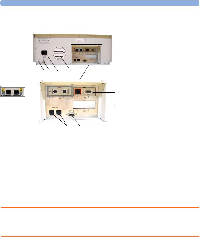
1Reserved for future use: protective earth intended for use in system installations.
2Equipotential grounding point
3Power cord connector
4Loudspeaker
5Slot 01 for optional LAN / RS232 system interface (for connection to an obstetrical information and surveillance system)
6Slot 02 for optional interfaces:
5
• Either dual PS/2 system interface
(A) for mouse and keyboard
7connection)
•Or MIB interface (B) for external touch screen connection
7Slot 03 reserved for future use
8Video output (VGA)
9Telemetry interface. If not using one of the fetal sensor sockets, one Avalon CTS can be connected at a time to either socket using the M2732-60001 interface cable (with black connector).
Connecting the Monitor to AC Mains
The monitor is an electrical Class I device in which protection against electric shock does not rely on basic insulation only, but which includes an additional safety precaution, in that means are provided for the connection of the equipment to a protective earth conductor in the fixed wiring installation in such a way that accessible metal parts cannot become live in the event of a failure of the basic insulation.
WARNING • Always use the supplied power cord with the earthed mains plug to connect the monitor to an earthed AC mains socket. Never adapt the mains plug from the power supply to fit an unearthed AC mains socket.
• Do not use AC mains extension cords or multiple portable socket-outlets.
Connecting the Monitor to Non-Medical Devices
Connect the monitor to an obstetrical surveillance system, such as OB TraceVue, via the optional system interface. For cabling requirements, refer to “Cabling Options and Requirements for Connection to OB TraceVue” on page 9. For safety-related information, refer to “Connecting NonMedical Devices” on page 8, and “System Test” on page 38.
15

3 Installation Instructions |
Connecting a Remote Display via the MIB/RS232 Interface |
Connecting a Remote Display via the MIB/RS232 Interface
The configuration of a specific MIB/RS232 port can be viewed in Configuration Mode and altered in Service Mode. This is required when a remote display with touchscreen is installed. To configure an MIB/RS232 port to support a slave display with touchscreen:
1Select Main Setup.
2Select Hardware.
3Select Interfaces.
4Select MIB/RS232.
5Select Touch 1.
NOTE Be aware that if you configure a port, this assignment is retained after a boot up. If the MIB/RS232 board is removed and replaced with a different type of board the settings are deleted. If the MIB/ RS232 board is then refitted, you must reconfigure the MIB/RS232 port. The configuration of MIB/ RS232 is not cloned between monitors.
After loading the Factory Defaults, you will need to reconfigure the MIB/RS232 port to re-enable the touch operation of the connected remote display.
Installing a Remote Display
The monitor is tested and approved for use with the following remote displays:
•Philips M8031B 15” Remote Display
•Philips M8033C 17” Remote Display
The monitor has an analog-only video output signal, with VGA resolution. Use a standard VGA video cable to connect the remote display to the video output on the rear of the monitor.
Mounting Remote Displays
Mounting solutions for the M8031B and M8033C remote displays must be purchased separately. Please refer to the installation instructions which ship with the mounting solution purchased.
Before Using the Monitor
WARNING Before starting monitoring, check that the configuration meets your requirements.
Check that the following configuration settings are suitable:
•Line Frequency
•Paper Scale
•Paper Speed
•Equipment Label
•Configured SmartKeys
16

Before Using the Monitor |
3 Installation Instructions |
•Input device configuration (if using an external keyboard or mouse)
•Remote display settings (if using a remote display, see “Connecting a Remote Display via the MIB/ RS232 Interface” on page 16).
If you need to enter configuration mode to change settings:
1 In the Main Setup menu, select Operating Modes.
2Select Config and enter the passcode.
The passcode for configuration mode is given in the monitor’s service documentation.
The monitor displays Config at the right hand side of the status line and in the center of the Screen while you are in configuration mode.
Before you leave configuration mode, always be sure to store any changes you made. You must store changes made to each Settings Block and to each Profile, individually. As it may be difficult to remember whether the settings you changed belong to a Monitor Settings block or a Measurement Settings block, we recommend that you store each block before you leave configuration mode.
To leave configuration mode:
1Enter the Main Setup menu.
2Select Operating Modes.
3Select Monitoring.
Checking and Setting Line Frequency
Before using the monitor, check that the line frequency setting is correct for your location, and change the setting if necessary in Service Mode.
WARNING An incorrect line frequency setting can affect the ECG filter, and disturb the ECG measurement. Ensure the line frequency setting is correct.
To set the line frequency:
1Enter the Main Setup menu.
2Select Global Settings.
3Select Line Frequency and select 50Hz or 60Hz from the pop-up list.
Checking/Setting Paper Scale
Check the paper Scale Type (US for paper with a scale of 30-240, or Internat’l for paper with a scale of 50-210) in the Fetal Recorder menu. In Monitoring Mode, you can see this setting (grayed out), but you cannot change it. It can be changed in Configuration Mode.
1Enter the Main Setup menu by selecting the SmartKey  .
.
2Select Fetal Recorder.
3Check the current setting for Scale Type. If it is not appropriate, change it in the Fetal Recorder menu in Configuration Mode:
Select Scale Type to toggle between US and Internat’l.
17

3 Installation Instructions |
Before Using the Monitor |
Checking/Setting Paper Speed
Check the paper speed before using the monitor. You can choose a paper speed of 1, 2, or 3 centimeters per minute (cm/min). The default setting is 3 cm/min. In Monitoring Mode, you can see this setting (grayed out), but you cannot change it. It can be changed in Configuration Mode.
As a change in paper speed results in a change in the appearance of a FHR trace, you are advised to ensure ALL monitors in your institution are set to the same speed.
To set the paper speed:
1Enter the Main Setup menu using the SmartKey  .
.
2Select Fetal Recorder.
3In the Recorder menu, you can see the current speed setting. Select Recorder Speed.
4Select the desired speed from the given choices: 1, 2 or 3 cm/min.
Configuring the Equipment Label
OB TraceVue requires a unique equipment label. In OB TraceVue, is possible to prevent connection to monitors with specific equipment labels by means of a filtering mechanism. For more details, see the OB TraceVue Instructions for Use.
1 Select the Bed Label screen element to call up the Bed Info menu.
2Select Equipment Label to call up the onscreen keyboard.
3Enter the system identifier.
Configuring SmartKeys
Check that the configured SmartKeys are suitable. Configure the SmartKeys preferred by the institution from a global list Global Smart Keys. The global list of SmartKeys is stored as a unique monitor setting in the monitor configuration. See the section “Configuring Global SmartKeys” on page 138 for details on how to configure the global SmartKey list.
PS/2 Keyboard/Mouse
Switch off the monitor before connecting any PS/2 compatible device.
Connect the PS/2 connector to the PS/2 Interface board in the monitor at the slot indicated by the appropriate symbol.
The default keyboard language setting for all initial configurations is “US”.
To configure the keyboard language manually, go to Service Mode, select Main Setup -> Hardware -> Keyboard and then select the proper language. Please note that this setting does not clone.
18

4
Theory of Operation
This chapter describes the functional operation of the monitor and the transducers. It incorporates features of the mechanical design, indicating the physical relationship of the assemblies and components.
Monitor Hardware Overview
|
|
|
|
|
|
|
Power |
||
|
Standby |
|
|
|
|||||
|
|
|
|
Interrupt |
|||||
|
Button |
|
|
|
|||||
|
|
|
|
Bleeper |
|||||
|
|
|
|
|
|
|
|||
|
|
|
|
|
|
|
|
|
|
AC-DC |
|
|
Stand-by |
|
|||||
|
|
|
|
|
|
Control |
|
||
|
|
|
|
|
|
|
|||
|
|
|
|
|
|
|
|
|
|
|
|
|
|
|
|
|
|
|
|
|
|
|
|
|
|
|
|
|
|
|
|
|
|
|
|
|
|
|
|
Main CPU Board
NBP
API |
Peripheral Interfaces Board) |
|
(All |
 IF Board 1 (LAN/ RS232)
IF Board 2
Telemetry |
Telemetry |
|
|
Connector Block |
|
|
|
Interface |
|
|
|
|
|
|
|
Audio |
|
Loudspeaker |
|
Amplifier |
|
|
|
|
|
|
|
|
Printhead |
|
|
Printer |
Paper |
|
|
Control |
|
|
|
Sensor |
|
|
|
|
|
|
|
|
Stepper |
|
|
|
Motor |
|
|
Touch |
|
Touch |
|
Control |
|
Screen |
|
|
Display |
Display |
|
Display |
Adapter |
Panel |
|
|
|
|
|
Control |
|
Backlight |
|
|
|
|
|
|
Block |
Converter |
VGA |
Bus |
|
Connector |
|
|
|
||
Master |
Connector |
|
|
SpO2 |
|
|
|
|
|
|
|
Floating |
Sensor |
|
|
|
|
|
|
Isolation |
Fetal |
|
|
|
|
|
|
|
optional boards |
|
|
standard boards
19

4 Theory of Operation |
Power Supply |
The monitor consists of the following main functional components:
•Power supply
•API (All Peripheral Interfaces) Board
•Main CPU Board
•Fetal Recorder (Thermal Printer Unit)
•Fetal Sensor Connector Block
•Noninvasive Blood Pressure Board
•SpO2 Board
•Input /Output Interface Boards:
–LAN / RS232
–Dual PS/2 (optional)
–MIB / RS232 (optional)
Power Supply
The power supply is a wide-range input switching unit, with an output of 24V. It is located in the chassis assembly.
Fetal Sensor Connector Block
Any compatible fetal transducer can be connected in any order to the monitor via the sockets on the Connector Block. The Connector Block is located on the Bus Master section of the All Peripheral Interfaces (API) Board, and is exchangeable.
API (All Peripheral Interfaces) Board
The All Peripheral Interfaces (API) Board is connected to the Main CPU Board by a 154-pin 0.5 mm pitch press fit connector.
The recorder is controlled by the Printer Control section of the API Board, which is connected to the Stepper Motor and the Thermal Printer Unit.
The signals from the transducers or sensors are conveyed from the sensor sockets to the Bus Master section of the API Board. The Telemetry Interface is also integrated into the API Board.
The Bus Master section is responsible for transducer detection, communicates with the connected transducers via a CAN bus, and communicates parameter data to the Main CPU Board via a serial link for further processing and display. It has floating power isolation.
The API Board also controls the display panel and the backlight converter, and also controls the touchscreen. The display panel is connected to the API Board. The VGA connector is also connected to the API Board.
The API Board incorporates an audio amplifier which controls the loudspeaker.
20
Loading...