


 Loading...
Obstetrical Care
S E R V I C E G U I D E
Avalon CTS
Cordless Fetal Transducer System
M2720A
F E T A L M O N I T O R I N G
Printed in Germany 10/04
*M2720-9000C*
Part Number M2720-9000C
4512 610 04681
S

Avalon CTS
Cordless Fetal Transducer System
M2720A
S E R V I C E G U I D E
M2720-9000C
October 2004
Printed in Germany

ii

Contents
1 General Information |
|
1 |
Who Should Read This Guide |
1 |
|
What to Do Next |
1 |
|
Repair Strategy |
2 |
|
Pre-Installation Considerations |
2 |
|
When is the Avalon CTS Customer Installable? |
2 |
|
When are Special Configurations Needed? |
3 |
|
Warnings, Cautions and Important Information |
3 |
|
Symbols on the System |
3 |
|
Patient Safety |
4 |
|
Protective Earth |
5 |
|
Environment |
5 |
|
General Description |
5 |
|
Mounting Solutions |
6 |
|
Applying the Velcro Fixing Tape |
7 |
|
Antenna Extension Mounting Kit |
8 |
|
Mounting on Philips Carts |
8 |
|
Mounting on Wooden Carts and Other Flat Surfaces |
9 |
|
Considerations for Choice of Configuration |
9 |
|
Frequency Bands |
9 |
|
Standard Delivery Configuration |
10 |
|
When is a Different Configuration Needed? |
10 |
|
When the Area of Reach is Not Sufficient |
10 |
|
When the Standard Configuration is Unsuitable |
10 |
|
Japanese Systems |
10 |
|
Multi-Region Base Station |
11 |
|
Frequency Planning |
11 |
|
Setting Expectations |
11 |
|
Antenna System Guidelines |
12 |
|
Before You Install an Antenna System |
12 |
|
Specifications |
13 |
|
Mixed Telemetry Devices on the Same M2600A Antenna System |
13 |
|
2 Theory of Operation |
15 |
|
|
|
|
Receiver Board |
16 |
|
Human Interface Board |
16 |
|
Power Supply |
16 |
|
Slot Control and Monitor Interface Board Hardware |
16 |
|

Transducer Hardware Overview |
17 |
Functional Description of the RF/CPU Hardware |
17 |
Base Station Communication |
18 |
Power Supply and Battery Charger |
18 |
Modulator |
18 |
RF Transmitter |
18 |
Toco Frontend Hardware |
18 |
Ultrasound Frontend Hardware |
18 |
ECG Frontend Hardware |
18 |
3 System Interfaces |
21 |
|
|
Fetal Monitor Interface |
21 |
Service Interface |
22 |
Compatible Fetal Monitors |
23 |
4 Disassembly/Reassembly |
25 |
|
|
Introduction |
25 |
Removing the Top Cover Assembly |
26 |
Replacing the Top Cover Assembly |
27 |
Changing Fuses |
28 |
Changing the Power Supply/Metal Chassis Assembly |
31 |
5 Spare Parts |
39 |
|
|
Exchange Parts |
39 |
Non-Exchange Parts |
40 |
Supplies and Accessories |
40 |
Antenna and Base Station Part Numbers |
41 |
6 Preventive Maintenance and Safety |
43 |
|
|
Care and Cleaning |
43 |
Recommended Frequency of Testing |
43 |
Performance Assurance Tests |
44 |
Self Test |
44 |
Parameter Test |
44 |
Testing Alarms |
45 |
Safety Tests |
45 |
Safety Test Procedures |
46 |
When to Perform Safety Tests |
46 |
How to Carry Out the Test Blocks |
47 |
Description of Applicable Safety Tests |
48 |
S(1): Protective Earth Test |
48 |
S(2): Enclosure Leakage Current Test |
|
- Normal Condition (NC) |
48 |
S(3): Enclosure Leakage Current Test |
|
- Single Fault Condition (SFC) Open Supply |
49 |

S(4): Enclosure Leakage Current |
|
- SFC Open Earth (Ground) |
49 |
Instrument Safety Test |
50 |
System Test |
50 |
What is a Medical Electrical System? |
50 |
General Requirements for a System |
50 |
System Example |
51 |
Regular Preventive Maintenance |
51 |
Mechanical Inspection |
51 |
Visual Check |
52 |
Toco Ventilation/Belt Button |
52 |
Testing the Ventilation Membrane |
52 |
Battery Check |
53 |
Starting the Battery Check |
53 |
Stopping the Battery Test |
54 |
Stages of the Battery Check |
54 |
Reading Battery Check Data Using the Service Support Tool |
55 |
Battery Exchange |
55 |
7 Troubleshooting |
57 |
|
|
System is Completely Inoperative |
57 |
System Reset |
57 |
Common Problems |
58 |
Troubleshooting a Cordless System: an Overview |
59 |
Checking Contacts |
60 |
Checking the Fetal Monitor |
60 |
RF Problems |
60 |
Carrier to Noise Ratio |
60 |
Gathering Data |
61 |
Observe System Performance |
61 |
Question the User |
61 |
Area of Reach |
62 |
Range Definition |
62 |
Using the Base Station |
62 |
Using the Service Support Tool |
63 |
RF Interference |
63 |
One-Channel or Narrowband Interference |
63 |
Broadband Interference |
64 |
Guidelines for Channel/Frequency Configuration |
64 |
Scanning the Available Frequency Range |
64 |
Excluding Frequencies |
65 |
Base Station with Fixed Frequency |
65 |
Transducers with Fixed Frequency |
66 |
Transducers for Japan |
66 |

|
Multi-Region Base Station |
66 |
|
Delivery Status |
66 |
|
Installation |
66 |
|
Testing Transducers |
67 |
|
Ultrasound Transducer Electrical Check |
67 |
|
TOCO Transducer Electrical Check |
68 |
|
ECG Transducer Electrical Check |
69 |
|
In DECG Mode |
69 |
|
In MECG Mode |
70 |
|
Troubleshooting the Top Cover |
71 |
|
Function Buttons |
71 |
|
Display/Window |
72 |
|
LEDs |
72 |
|
Magnets |
72 |
|
Factory Information Code Log |
72 |
|
8 Changing Settings |
73 |
|
|
|
|
Configuration Settings |
73 |
|
Function Settings |
74 |
|
Bed Label Appearance |
74 |
|
Enabling/Disabling Fixed Frequency |
74 |
|
Selecting the Channel Frequency Spacing |
75 |
|
Action Settings |
77 |
|
Displaying the Software Revision |
77 |
|
Clearing the Factory Information Code (FIC) Log |
77 |
|
Starting the Battery Check |
78 |
|
9 Upgrades |
79 |
|
|
|
10 Specifications |
81 |
|
|
|
|
|
General |
81 |
|
Base Station |
81 |
|
Transducers |
82 |
|
Frequency Bands |
83 |
|
Frontends |
83 |
|
Cables |
84 |
|
Electromagnetic Compatibility (EMC) Specifications |
85 |
|
Emissions and Immunity |
85 |
|
Electromagnetic Immunity |
85 |
|
Finding Recommended Separation Distances |
86 |
|
Recommended Separation Distances from Portable and Mobile RF Communication |
|
|
Equipment |
88 |

ARemoving and Replacing the Transducer Battery
BRemoving and Replacing the Transducer Belt Button
CAvalon CTS Frequency Table
89
91
93

1
General Information
This guide tells you how to service and repair the base station (M2720A) and transducers (M2725A, M2726A, and M2727A) of the Avalon CTS Cordless Fetal Transducer System. It describes the system hardware and software, tells you how to diagnose operating and servicing problems, and how to test the system.
As this system is intended to be installed by the customer, refer to the Instructions for Use for details of how to install the system. See also “Pre-Installation Considerations” on page 2.
The Avalon CTS Cordless Fetal Monitoring System Service Guide supplements the maintenance and troubleshooting procedures, carried out by the operator, that are described in the Instructions for Use. Refer to the Instructions for Use for maintenance and troubleshooting procedures that may be performed during normal operation.
Only qualified service personnel should attempt to install the system, disassemble the base station, remove or replace any internal assemblies, or replace the transducer batteries or belt buttons.
Who Should Read This Guide
This guide is for any qualified technical personnel servicing and repairing the Avalon CTS Cordless Fetal Transducer System.
You must:
•understand English
•be familiar with standard medical equipment installation procedures
•be familiar with current conventional technical terms as used throughout this guide
What to Do Next
Familiarize yourself with the contents of this guide and the Instructions for Use before attempting to service or repair the system.
1

1 General Information |
Repair Strategy |
Repair Strategy
The Service Support Tool software helps you to determine whether a fault is a hardware, software or RFrelated problem. Any maintenance and repair procedures beyond the level covered in the Instructions for Use are limited to:
•unit exchange for
–the base station
–the transducers
•replacement of
–the top cover assembly, including human interface board
–the power supply, including metal chassis
–two fuses in the power supply
–the transducer battery
–the transducer ventilation knob
Repair or replacement of individual components on the boards is not supported, and should never be attempted.
For any problem related to connecting the base station to an antenna system, refer to the M2600A Telemetry System’s Service Training and Reference Guide.
For tests that you are required to perform after repairs, refer to “When to Perform Safety Tests” on page 38.
Pre-Installation Considerations
There are a number of factors you need to consider that influence how you install the Avalon CTS.
When is the Avalon CTS Customer Installable?
The Avalon CTS is intended to be customer installable under the following conditions:
•The system in its standard configuration is an “out-of-the-box”, standalone system, delivered with automatic frequency allocation, and is intended to be used with the standard antenna supplied, giving a line-of-sight operating range up to 100m/300ft.
•There are less than ten stand-alone systems in the institution.
•Connection to an antenna system is not planned.
•No other telemetry devices are used in the institution that can influence, or be influenced by, the Avalon CTS.
•There are no other sources of RF interference that influence the operation of the Avalon CTS.
•There are no country-specific regulations requiring special configuration.
Installation should be carried out by qualified technical personnel.
If you need to mount the Avalon CTS, or use the antenna extension mounting kit (M1361A Option 1AA), see page 8 for further details.
2

Warnings, Cautions and Important Information |
1 General Information |
When are Special Configurations Needed?
If one or more of the conditions above are not met, you need a special configuration of the Avalon CTS (refer also to “Considerations for Choice of Configuration” on page 9). For instance, you may need to:
•Set fixed frequencies when there are other telemetry systems installed in the same institution. (In Japan, local regulations always require the setting of fixed frequencies.) This configuration should be carried out by qualified service personnel, either from the hospital’s biomedical department, or from Philips.
•Connect the Avalon CTS to an antenna system because the standard antenna is not sufficient to cover the area intended for cordless monitoring. Site preparation, antenna system design (including guidelines for mixed telemetry equipment installations), and installation should be carried out by qualified service personnel from Philips.
•There are country-specific regulations requiring special configuration (in Japan, for example), or your country requires a Multi-Region base station.
Warnings, Cautions and Important Information
WARNING A warning alerts you to a potential serious outcome, adverse event or safety hazard. Failure to observe a warning may result in death or serious injury to the user or patient.
CAUTION A caution alerts you to circumstances where special care is necessary for the safe and effective use of the product. Failure to observe a caution may result in minor or moderate personal injury, damage to the product or other property, and possibly in a remote risk of more serious injury.
In this book, graphical symbols (indicators or elements of the base station or transducer displays) depicted in this way indicate that they are blinking.
© Copyright 1995-2004 Koninklijke Philips Electronics N.V. All Rights Reserved.
Symbols on the System
This attention symbol indicates that you should consult this book and the Instructions for Use, and particularly any warning messages.
Power-On/Stand-by Switch.
Power-On/Stand-by Indicator.
Equipotential Terminal.
This symbol identifies terminals that are connected together, bringing various equipment or parts of a system to the same potential. This is not necessarily earth potential. The value of potentials of earth may be indicated adjacent to the symbol.
3

1 General Information |
Patient Safety |
|
Protective Earth Terminal. |
|
This symbol identifies the terminal for connection to an external protective earth system. |
|
|
|
Antenna input symbol. |
|
|
|
Service socket symbol. |
|
|
|
This symbol appears on the device adjacent to the CE mark and defines Class 2 radio equipment |
|
per Radio and telecommunications Terminal Equipment Directive 1995/5/EC. |
|
|
IPX1 |
Ingress Protection code according to IEC 60529. Base station is rated IP X1 (protection against |
|
vertical water drops only). |
|
|
IP68 |
Ingress Protection code according to IEC 60529. All transducers are rated IP 68 (protection |
|
against dust, access to hazardous parts, and the effects of continuous immersion in water to a |
|
depth of 0.5 meter for five hours). |
|
|
|
Type CF equipment. |
|
|
Patient Safety
The Telemetry System should only be used by, or under the direct supervision of, a licensed physician or other health care practitioner who is trained in the use of fetal heart rate monitors and in the interpretation of fetal heart rate traces. US federal law restricts this device to sale by, or on the order of, a physician.
The base station (telemetry receiver) is a Protection Class 1 instrument.
The device complies with the following safety standards:
•EN 60601-1:1990+A1:1993+A2:1995 / IEC 60601-1:1988+ A1:1991+A2:1995
•EN 60601-1-1:2001 / IEC 60601-1-1:2000
•UL2601-1:1997
•CAN/CSA C22.2 No. 601.1-M90
•JIS T 1001-1992
•JIS T 1002-1992
•AS 3200.1.0-1998
The cordless transducers are battery operated devices, applied parts (patient connectors) are Type CF 

 .
.
4

Protective Earth |
1 General Information |
Protective Earth
WARNING Check each time before use that the system is in perfect working order and the base station is properly grounded.
This equipment is intended for use only within healthcare facilities. It is not suitable for use in domestic establishments and in establishments directly connected to a low voltage power supply network, which supplies buildings used for domestic purposes.
Do not use additional AC mains extension cords or multiple portable socket-outlets. If a multiple portable socket-outlet without a separation transformer is used, the interruption of its protective earthing may result in enclosure leakage currents equal to the sum of the individual earth leakage currents.
To protect hospital personnel and the patient, the cabinet must be grounded. Accordingly, the base station is equipped with a 3-wire power cable which grounds it to the power line ground when plugged into an appropriate 3-wire receptacle. Do not use a 3-wire to 2-wire adapter with the base station. Any interruption of the protective earth grounding will cause a potential shock hazard that could result in serious personal injury.
Whenever it is likely that the protection has been impaired, the base station must be made inoperative and be secured against any unintended operation.
The patient cable must be positioned so that it does not come into contact with any other electrical equipment.
Before operation, make sure that the base station is free from condensation. This can form when equipment is moved from one building to another, and is exposed to moisture and differences in temperature.
Environment
Before operation, make sure that the base station is free from condensation. This can form when equipment is moved from one building to another, and is exposed to moisture and differences in temperature.
Use the system in an environment which is reasonably free from vibration, dust, corrosive or explosive gases, extremes of temperature, humidity, and so forth. It operates within specifications at ambient temperatures between 0°C and +45°C/32°F and +113°F. Ambient temperatures that exceed these limits can affect the accuracy of the system, the transmitter radio frequency transmission, and can damage the components and circuits.
The system can be stored at ambient temperatures between -20°C and +60°C/-4°F and +158°F.
The transducers are watertight to a depth of 0.5 meter/1.64 feet (rated IP 68).
The base station is protected against vertically falling water drops only (rated IP X1 according to IEC 60529).
General Description
Refer to the Instructions for Use for operating information for the base station and the transducers. It includes descriptions of the installation and setup of the system and modes of operation.
5

1 General Information |
Mounting Solutions |
Mounting Solutions
You can mount the Avalon CTS as follows:
•In a standard cart drawer. The base station with docked transducers fits into Philips Carts CL, CX and CM.
Note: if you mount the base station in a cart or in such a way that the standard antenna cannot be attached directly to the base station, or does not provide sufficient transmission range, use the antenna extension mounting kit (M1361A Option 1AA).
•On top of carts, desks or other flat surfaces using the mounting brackets.
•In a wide variety of situations using the GCX mounting adapter for mounting the base station (order directly from GCX, part number PH-0042-80).
•On top of Series 50 IX/XM/XMO fetal monitors using the mounting brackets.
Mounting Brackets
Contact your local Philips representative for additional cart mounting options.
Refer also to the fitting instructions that come with the relevant solution.
6
Applying the Velcro Fixing Tape |
1 General Information |
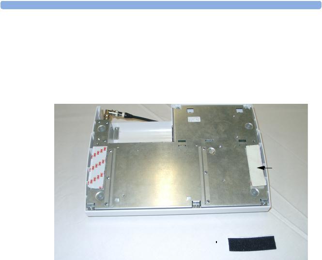
Applying the Velcro Fixing Tape
Two self-adhesive Velcro fixing tape sets are supplied, each set consisting of two halves.
1Strip off the paper backing on one half of the Velcro set and attach to one side of the underneath of the base station. Repeat for the other side.
2Strip off the paper backing on the other half of the Velcro set and attach to the fixing surface so that the two halves of the Velcro set mate up when the base station is correctly positioned.
Apply one half of Velcro tape in position shown
Apply other half of
Velcro tape to appropriate  place on fixing surface
7

1 General Information |
Antenna Extension Mounting Kit |
Antenna Extension Mounting Kit
If the base station is installed in a cart or other mounting solution where the standard antenna cannot be attached directly to the base station, or does not provide sufficient transmission range, use the antenna extension mounting kit (M1361A Option 1AA).
The kit contains:
•Antenna extension cable with BNC connectors (1.0m/3.3 ft. approx.)
•Mounting bracket, including fixings, for mounting onto Philips Carts.
The mounting bracket can also be fitted on walls, wooden carts, or other flat surfaces using fixings (not supplied) appropriate for the surface material.
Mounting on Philips Carts
A
C
B
1Remove the plastic cover (A).
2Slide the fixings for the mounting bracket (C) into the groove (B) in the cart.
3Replace the plastic cover (A) before sliding the mounting bracket fully down.
4Slide the mounting bracket downwards in the groove (B) in the cart until the antenna holder part of the bracket rests on the plastic cover.
5Tighten the fixing screws to secure the mounting bracket.
8

Considerations for Choice of Configuration |
1 General Information |
Mounting on Wooden Carts and Other Flat Surfaces
Considerations for Choice of Configuration
There are a number of factors that can influence how you finally configure the Avalon CTS.
Frequency Bands
Depending on the country of use, the system uses radio frequencies within one of three ranges, the Wireless Medical Telemetry Systems (WMTS) band, the Industrial, Scientific and Medical (ISM) band, or a range of bands specific to Japan. The actual approved frequencies used depend on country-specific regulations.
The following diagram gives an example overview of the system’s frequency band configuration.
5
4
3
2
1
1 = The full (hardware) frequency range (10 MHz wide).
2 = The country-specific frequency range governed and approved by local regulatory bodies.
3 = The available frequency range: shows the real, current frequency range available within the country range. This will differ from the country range due to:
–excluded frequency ranges
–frequency ranges already allocated to other Avalon CTS systems in the same establishment.
4 = Excluded frequency ranges (ranges occupied by other telemetry systems, or other RF interferers).
5 = Fixed frequency ranges.
9

1 General Information |
Considerations for Choice of Configuration |
Standard Delivery Configuration
The Avalon CTS is normally delivered with:
•Automatic channel search.
•A standard antenna.
Using the standard antenna, the potential operating range is up to 100 meters/300 feet. The actual effective area of reach will vary according to the geographical and physical characteristics of the building where the system is installed, and is also influenced by the presence of other radio frequency (RF) devices or interference. We recommend that you define effective operating range prior to putting the system into operation.
If the area of reach is adequate for the intended monitoring area, and the system’s operation is not influenced by other RF sources, then the normal delivery configuration is sufficient.
When is a Different Configuration Needed?
This section deals with possible reasons why the standard delivery configuration may not be adequate.
When the Area of Reach is Not Sufficient
If the area of reach is not sufficient using the standard antenna supplied with the system, there are a few things to consider:
–The placement of the antenna has an effect on the operating range. If it is located inside a metal cart or other RF-absorbing material, then place the antenna externally by using the Antenna Extension Mounting Kit (M1361A Option 1AA) to increase the range.
–Check the orientation of the antenna. In general, the antenna provides the greatest range when it is positioned vertically.
–If the area of reach is still insufficient, consider installing an antenna system.
When the Standard Configuration is Unsuitable
The standard configuration, with free base station channel search, may be unsuitable if:
•There are other telemetry or RF systems installed in the hospital.
•There are multiple (more than ten) stand-alone Avalon CTS systems.
•There are other sources of RF interference, for instance, broadcasting stations, microwave devices, and wireless temperature sensors.
•You connect the Avalon CTS to an antenna system.
•There are country-specific regulations requiring special configuration (in Japan, for example), or your country requires a Multi-Region base station.
Japanese Systems
Transducers must use fixed frequencies. They are initially shipped from the factory with no frequencies assigned to them. During installation, they are initialized, and their frequencies are set. (See also “Transducers for Japan” on page 66.)
10
Setting Expectations |
1 General Information |
Multi-Region Base Station
For countries requiring the Multi-Region base station (for example, Norway and Singapore), the receiver in the base station is “disabled” before it leaves the factory. The correct approved frequency range is then enabled locally during installation using the Service Support Tool. (See also “Multi-Region Base Station” on page 66.)
Frequency Planning
For Japan and countries using the Multi-Region base station, and for multiple cordless/telemetry installations in the same hospital, an RF frequency plan should be implemented. Document all frequencies or frequency ranges occupied by:
•Other telemetry systems (adult and fetal).
•Multiple Avalon CTS systems (operating on fixed frequencies). Remember that the Avalon CTS is also a potential interference source for other RF systems.
•Other sources of RF interference (other electrical equipment, broadcasting stations, or paging systems, for instance).
Once you have identified all the occupied frequencies or frequency ranges (for example, by using the Service Support Tool software) you can change the system’s configuration by following the guidelines for RF channel/frequency configuration.
•Exclude frequency ranges already occupied by other telemetry systems or that are subject to interference from other RF sources (see page 65).
•Use fixed frequencies for the base station, possibly in conjunction with altering the channel spacing (see page 74).
•Use fixed frequencies for the transducers (see page 66).
Setting Expectations
No matter how good a telemetry system design is, it will always experience occasional loss of radio communications, resulting in US/Toco/ECG dropouts. A telemetry system will never be as reliable as a hard-wired monitor that transmits its signal through a wire. If occasional loss of US/Toco/ECG monitoring is not acceptable for certain patients, they should be connected to a hard-wired bedside monitor.
WARNING Telemetry should not be used for primary monitoring in applications where the momentary loss of the US/ Toco/ECG signal is unacceptable.
Following are guidelines to set proper expectations of hospital staff and to improve system performance:
•Clinicians will tend to see more motion related artifact on the US/Toco/ECG measurements of ambulatory patients than on patients that are restricted to a bed.
•Patients should be restricted to the designated coverage area. Monitoring performance will degrade if patients go outside the radius of coverage of the receiving antenna.
11

1 General Information |
Antenna System Guidelines |
•Keep the size of the antenna system as small as possible. Telemetry system performance will degrade as the system size increases. The larger a system is, the greater the potential for receiving interfering signals. In addition, as more devices are added to the antenna system, the noise generated by the antenna system itself increases.
•A patient location protocol is critical to a telemetry system. If a life-threatening event occurs, the clinician must be able to locate the patient quickly. The importance of this increases as the antenna system size increases.
•Philips Medical Systems has no control over the RF environment in the hospital. If interference exists at the operating frequencies, telemetry system performance will be affected. Careful selection of frequencies for all wireless devices used within a facility (telemetry transmitters, walkie-talkies, ambulance radios, other wireless medical devices, etc.) is important to prevent interference between them. Frequency management is the responsibility of the hospital.
Antenna System Guidelines
The Avalon CTS (M2720A) is compatible with the dual band antenna system components used with the M2600A adult telemetry system. Antenna systems must be designed according to adult telemetry system rules, and presales activities and site preparation must be done according to the existing M2600A series antenna system rules. These activities are not bundled into the product price and have to be ordered separately from the Philips Medical Support Organization.
In addition to the M2600A antenna system design rules, the following antenna specifications apply to the Avalon CTS:
•Only original M2600A antenna system components will be supported.
•The antenna spacing must not exceed a radius of 10m (32ft).
•Existing antenna systems used for M1310A with 15.5m (51ft) antenna radius spacing do not comply and must be redesigned to work with the Avalon CTS.
•A mixture of Avalon CTS and other supported Philips telemetry devices (for example, M1310A or M2600A Adult Telemetry Transmitter/Receiver) on the same antenna system may be supported. Please see below for further details of how to configure and design a mixed telemetry system.
•Frequency converters used in USA with M2600A adult telemetry cannot be used with the Avalon CTS.
•Contact Philips Support regarding antenna system design.
Before You Install an Antenna System
In general, before each antenna system installation, a site frequency plan is required which includes an appropriate frequency plan for M2720A and all other telemetry devices used in the same hospital.
Using the results of this frequency survey, the appropriate frequency allocation mode must be set for the M2720A, for example, automatic frequency allocation mode or fixed frequency mode for the base station. Under normal circumstances, the fixed frequency mode for the transducer should not be used, except for Japan. See the Service Support Tool Help for further information about choices of frequency allocation modes.
An antenna system for the M2720A should be designed by an antenna expert experienced in designing M2600A antenna systems. For antenna system calculations, the specifications for M2720A can be added to the Antenna System Design Spreadsheet. This is important, because most antenna systems for the M2720A are non-standard in design, as the RF signal typically needs to be distributed to several rooms.
12

Antenna System Guidelines |
1 General Information |
Specifications
Antenna system calculations for fetal telemetry differ from those of adult M1402A or M2602A mainframe systems. The M2720A uses an internal signal amplifier, requiring the antenna system to have a 0db to -3db gain at the final antenna connection to the Avalon CTS.
The minimum carrier to noise ratio (CNR) should be 8dB.
M2720A Avalon CTS typical specifications:
M2720A |
Maximum Input |
CNR |
Gain |
NF |
TOI |
P1dB |
|
Frequency Band |
Before Saturation |
@100KHz |
|||||
|
|
|
|
||||
|
|
|
|
|
|
|
|
ISM |
0 to -3db |
8 dB |
14.1 dB* |
7.36* |
5 dBm* |
-4 dBm* |
|
(433-443 MHz) |
|
|
|
|
|
|
|
Japan |
0 to -3db |
8 dB |
14.6 dB* |
6.86* |
5 dBm* |
-4 dBm* |
|
(420-430 MHz) |
|
|
|
|
|
|
|
WMTS |
0 to -3db |
8 dB |
11.1 dB* |
8.55* |
5 dBm* |
-4 dBm* |
|
(608-614 MHz) |
|
|
|
|
|
|
|
|
|
|
|
|
|
|
*Can be added to the antenna design spreadsheet as M2720A-specific parameters
Mixed Telemetry Devices on the Same M2600A Antenna System
A mixture of M2720A and other supported Philips telemetry devices (for example, M1310A or M2600A Adult Telemetry Transmitter/Receiver) on the same antenna system are supported under the following conditions:
•M2600A antenna system design rules are followed.
•Antenna input must be within the range of 0dB to -3dB.
•Each Avalon CTS channel must be separated by a minimum of 100 KHz from any non-Avalon frequency channel.
•The internal channel frequency spacing between Avalon CTS transducers should be 25 KHz (factory default setting).
Example:
A Series 50 T Fetal Telemetry System (M1310A) is already connected to an antenna system, and its transmitter is set to 433.650 MHz. You need to connect an Avalon CTS to the same antenna system. In this case, the first usable frequency channel for any M2720A transducer is either 433.550 MHz or 433.750 MHz, as each transducer frequency channel must be separated by at least 100 KHz from any frequency channel used by any telemetry device other than Avalon CTS transducers.
13

1 General Information |
Antenna System Guidelines |
14

2
Theory of Operation
This chapter describes the functional operation of the system, including the base station and transducers. It incorporates features of the mechanical design, indicating the physical relationship of the assemblies and components.
Base Station Hardware Overview
Figure 1 Base Station Boards
15

2 Theory of Operation
The Base Station consists of four functional components:
Receiver Board
The receiver is a double superheterodyne narrowband frequency modulation (FM) receiver, with two mixers and two intermediate frequencies (IFs). Three radio frequency (RF) signals can be received independently with three identical receiver channels. The digital section of the main CPU is responsible for frequency shift key (FSK) detection, analog-to-digital conversion of the low frequency (LF signal), signal filtering, and radio frequency (RF) channel management. The main CPU communicates with the transducers. While charge power is on, a serial communication link is established between the base station and each docking slot.
Human Interface Board
The Human Interface (HIF) board provides the user interface, and the display, indicators, keys and the slot charging contacts are all located on this board.
Power Supply
The power supply is a wide-range input swtching unit, with an output of +48V. It is located on the chassis assembly.
Slot Control and Monitor Interface Board Hardware
The Monitor Interface (MIF) board provides the interface to the fetal monitor as well as the communication interface to the transducer slots. Power conversion is performed by a DC-DC converter. The digital (active) parts of the human interface also reside on this board.
The MIF board consists of the following functional blocks:
•DC-DC Converter - the 48V DC input for the DC-DC converter comes from the primary AC-DC converter. Since the 48V DC voltage is sufficiently stabilized, two fixed pulse width step down transformers are used to transform the high voltage down to the required 3V, 5V and 12V (postregulated for accuracy).
The +12V supply is mainly used for battery charging and you can access this voltage at the charge contacts. The fuse on the MIF board are not replaceable, and if it blows, the board must be replaced. If there is a short to ground, unlimited current will blow the fuse. To avoid this, a current limiter is used to limit the output current.
•Monitor interface - three major blocks make up the monitor interface:
–PWM Toco digital-to-analog (D/A) converter
–Two PWM wave D/A converters for FHR low frequency (LF) 1, and FHR LF 2.
–Digital status ports
•Transducer slot interface - this block is responsible for transducer detection, safety features of the charge power switch, serial communication between base station and transducers and synchronization clock generation for the power supply. To ensure that there is no charge power applied to the charge contacts when there is no transducer docked in a slot, charge power in each slot is only applied after a transducer has been detected.
•Drivers for the HIF board interface - this block contains the multiplexing and driving components for the function buttons, the display backlight and the seven-segment LEDs.
16
Transducer Hardware Overview |
2 Theory of Operation |
Transducer Hardware Overview
The system has three transducer types:
•Toco
•US
•ECG
They all share the same modulation and digital processor circuitry, power supply, liquid crystal display, and RF transmitter. The processor software is also the same for all transducers. The frontends, however, are specific to each transducer type.
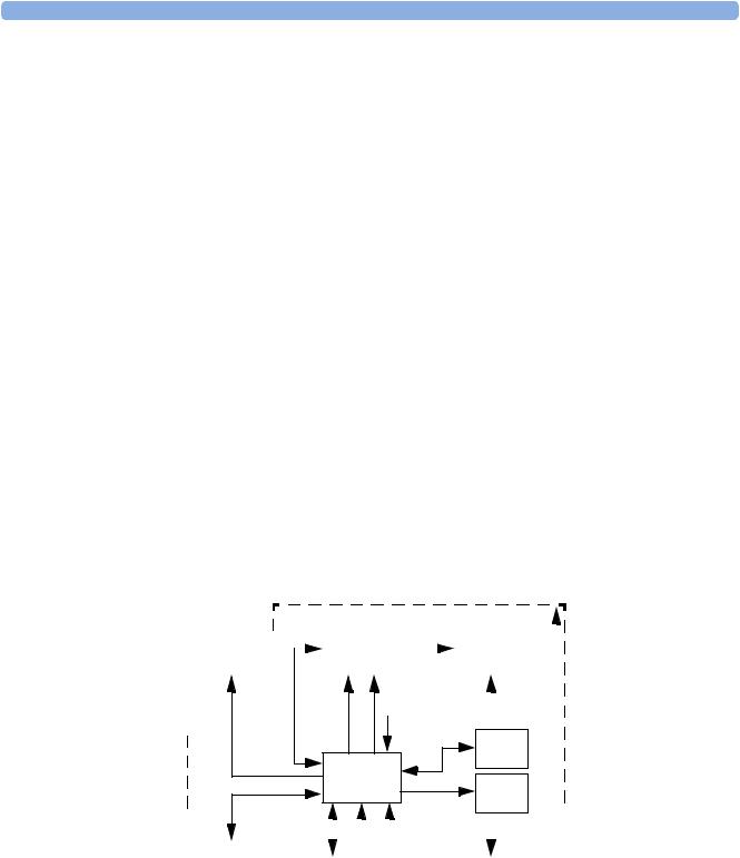
Functional Description of the RF/CPU Hardware
The RF/CPU section of the transducers is made up of the following functional blocks:
•CPU (micro controller)
•LCD
•Base Station communication
•EEPROM
•FLASH download port
•Clock generator
•Power supply and battery charger
•Modulator
•RF transmitter
Boards: M2725-66501,
M2726-66501,
M2727-66501
parameter |
|
|
|
|
|
|
|
modulation signal |
|
RF |
|
|||||||||
frontends |
|
|
wave |
|
Modulator |
(wave +FSK) |
|
|
||||||||||||
|
(see separate description) |
|
|
|
|
|
|
|
transmitter |
|
||||||||||
|
|
|
|
|
|
|
|
|
||||||||||||
|
|
|
|
|
|
|
|
|
|
|
|
|
|
|||||||
|
|
|
|
|
|
|
|
|
|
|
|
|
|
|
|
|
|
|
|
|
|
|
|
|
|
|
|
|
|
|
|
|
|
|
|
|
|
|
|
|
|
|
|
|
|
|
|
|
|
|
|
|
gain control |
FSK signal |
|
|
|
|||||
|
|
|
|
|
|
|
|
|
|
|
|
|
|
|||||||
|
|
|
|
|
|
|
|
|
|
|
|
|
frequency control |
|
|
|
||||
|
|
|
|
|
|
|
|
|
|
|
|
|
|
|
|
|
|
|||
|
|
|
|
|
|
|
|
|
|
|
|
|
|
|
|
|
|
|||
|
|
|
|
|
|
|
|
|
|
|
|
|
|
|
|
|
|
|
|
|
|
|
|
|
|
|
|
|
|
|
|
|
|
|
|
|
|
|
|
|
|
|
|
FLASH |
|
|
|
download |
|
|
CPU |
port |
|
frontend control |
|
||
power management |
(micro |
LCD |
|
controller) |
|||
|
|||
|
|
|
|
|
|
|
|
|
|
|
|
|
|
|
|
|
|
|
|
|
|
|
|
|
|
|
|
|
|
|
|
|
|
|
|
|
|
|
|
|
|
|
|
|
|
|
|
|
|
|
|
|
|
|
|
|
|
|
|
|
|
|
|
|
|
|
|
|
|
|
|
|
|
|
|
|
|
|
|
|
|
|
|
|
|
|
power supply |
|
|
|
|
|
|
|
|
|
|
|
|
|
|
|
|
|
|
|
|
|
|
|
|
|
|
|
|
|
|
|
||||||
|
|
|
and battery |
|
base station |
|
|
|
|
Clock |
|
|
EEPROM |
|
|
|
|
|||||||||||||||||||||||
|
|
|
|
|
|
|
|
|
|
|
|
|
|
|||||||||||||||||||||||||||
|
|
|
charger |
|
communication |
|
|
|
|
generator |
|
|
|
|
|
|
||||||||||||||||||||||||
|
|
|
|
|
|
|
|
|
|
|
|
|
|
|
|
|
|
|
|
|
||||||||||||||||||||
|
|
|
|
|
|
|
|
|
|
|
|
|
|
|
|
|
|
|
|
|
|
|
|
|
|
|
|
|
|
|
|
|
|
|
|
|
|
|
|
|
|
|
|
|
|
|
|
|
|
|
|
|
|
|
|
|
|
|
|
|
|
|
|
|
|
|
|
|
|
|
|
|
|
|
|
|
|
|
|
|
|
|
|
|
|
|
|
|
|
|
|
|
|
|
|
|
|
|
|
|
|
|
|
|
|
|
|
|
|
|
|
|
|
|
|
|
|
|
|
|
|
|
Figure 2 Transducer Block Diagram
17

2 Theory of Operation |
Toco Frontend Hardware |
Base Station Communication
An active base station communicates with docked transducers to check the correct transducer type, serial number, to program the RF frequency, to initiate test cycles, and to check the current battery status.
Power Supply and Battery Charger
A Lithium-Ion (Li-Ion) battery powers the transducer. Batteries are charged whenever a transducer is docked in an base station connected to AC power. Charge power is transferred by the spring-loaded, twopin charge contacts. Communication between the base station and the transducer processors is also done using these contacts.
An intelligent Li-Ion charging circuit in the transducer controls the battery management. See page 72 for battery charging times.
Modulator
The analog heart rate signals (ultrasound Doppler or fetal ECG) are pre-processed and band-limited by filters. The signals are then fed into a programmable gain amplifier controlled by an automatic gain control circuit and a digital FSK modulated subcarrier (1.6 kHz or 2.4 kHz) is added to the RF carrier signal. The subcarrier is responsible for the digital transmission of the Toco data, along with safety and status information, such as serial number, bed label, fetal movement data, battery information.
RF Transmitter
The RF transmitter block contains:
•a PLL synthesizer that divides the reference frequency down to 12.5 kHz, and can be tuned in steps of 12.5 kHz.
•a voltage controlled ocillator (VCO).
•a power amplifier (antenna driver).
Toco Frontend Hardware
Uterine activity is measured by evaluating the hardness of the mother’s abdomen with a pressure sensitive resistor bridge (DMS element). The DMS element requires an excitation voltage and its differential output signal is proportional to the pressure applied to the DMS element. An AC excitation voltage is used, and the resulting AC output signal is amplified and converted to a pressure proportional DC voltage by a synchronous rectifier followed by a low pass filter.
Ultrasound Frontend Hardware
The ultrasound frontend is a pulsed Doppler system with a 1.0 MHz ultrasound frequency, and a pulse repetition rate of 3.2 kHz. Seven ultrasound crystals are used as transmitter and receiver.
ECG Frontend Hardware
Several parameter frontends are combined on the ECG frontend board. Currently supported parameters are DECG and MECG.
18

ECG Frontend Hardware |
2 Theory of Operation |
A seven-pin ‘D-type’ socket carries all parameter related inputs and outputs. An external mode resistor, connected to one of the pins, detects which ECG mode to set when an adapter cable is plugged in. The M1362B ECG adapter cable, used with the M1364A patient module, is also used for the fetal scalp or adult electrodes.
19

2 Theory of Operation |
ECG Frontend Hardware |
20
Loading...