


Instructions for Use
Avalon Fetal Monitor
FM20/30, FM40/50
Release G.0 with Software Revision G.02.xx
Patient Monitoring

Table of Contents
|
1 Introduction |
9 |
Who this Book is For |
9 |
|
Confirm Fetal Life Before Using the Monitor |
10 |
|
Introducing the Avalon Family of Fetal Monitors |
11 |
|
|
2 Installation |
13 |
|
|
|
Installation Checklist |
13 |
|
Unpacking and Checking the Shipment |
14 |
|
Mounting the Monitor |
15 |
|
Mounting the External Power Supply (M8023A) |
15 |
|
Connecting the Monitor to AC Mains |
16 |
|
How and When to Carry Out the Test Blocks |
17 |
|
Safety Tests |
18 |
|
|
3 Basic Operation |
19 |
|
|
|
Supported Measurements |
19 |
|
Avalon FM20 and FM30 |
20 |
|
Avalon FM40 and FM50 |
21 |
|
Cordless Monitoring |
22 |
|
Getting to Know Your Avalon FM20/FM30 |
23 |
|
Getting to Know Your Avalon FM40/FM50 |
24 |
|
Operating and Navigating |
27 |
|
Operating Modes |
32 |
|
Automatic Screen Layouts |
33 |
|
Settings |
33 |
|
Checking Your Monitor Revision |
35 |
|
Preparing to Monitor |
35 |
|
Starting Monitoring |
53 |
|
Switching the Monitor to Standby |
54 |
|
After Monitoring |
54 |
|
Disconnecting from Power |
54 |
|
Troubleshooting |
55 |
|
|
4 Using Batteries (with FM20/30 Battery Option) |
57 |
|
|
|
External Power Supply M8023A |
58 |
|
Battery Power Indicators |
58 |
|
Battery Status Window |
60 |
|
Optimizing Battery Performance |
61 |
|
3

|
5 Alarms |
63 |
Alarm Mode |
63 |
|
Visual Alarm Indicators |
64 |
|
Audible Alarm Indicators |
64 |
|
Acknowledging Alarms |
66 |
|
Acknowledging Disconnect INOPs |
66 |
|
Pausing or Switching Off Alarms |
66 |
|
Alarm Limits |
68 |
|
Reviewing Alarms |
68 |
|
Latching Alarms |
69 |
|
Testing Alarms |
71 |
|
Alarm Behavior at Power On |
71 |
|
|
6 Patient Alarms and INOPs |
73 |
|
|
|
Alarm Messages |
73 |
|
Technical Alarm Messages (INOPs) |
76 |
|
|
7 Admitting and Discharging |
83 |
|
|
|
Admit/Discharge on the Monitor |
83 |
|
New Patient Check |
84 |
|
OB TraceVue: via LAN |
85 |
|
OB TraceVue: via RS232 |
85 |
|
|
8 Non-Stress Test Timer |
87 |
|
|
|
Setting NST Autostart/Autostop |
87 |
|
Viewing the NST Timer |
87 |
|
Timer Expiry Notification |
87 |
|
Accessing the NST Setup Pop-up Keys |
88 |
|
|
9 Non-Stress Test Report |
91 |
|
|
|
Setting Up an NST Report |
91 |
|
NST Report Status Window |
92 |
|
NST Reassurance Criteria |
94 |
|
Non-Reassuring Report |
94 |
|
Non-Reactive NST Test |
94 |
|
10 Monitoring FHR and FMP Using Ultrasound |
95 |
|
|
|
|
Technical Description |
95 |
|
Limitations of the Technology |
96 |
|
Misidentification of MHR as FHR |
96 |
|
Cross-Channel Verification |
97 |
|
What You Need |
97 |
|
Cordless Monitoring - Important Considerations |
97 |
|
Preparing to Monitor |
98 |
|
Selecting Fetal Heart Sound |
99 |
|
Changing the Fetal Heart Sound Volume |
99 |
|
4

Fetal Movement Profile |
100 |
|
Troubleshooting |
102 |
|
Additional Information |
103 |
|
Testing Ultrasound Transducers |
112 |
|
11 Monitoring Twin FHRs |
113 |
|
|
|
|
Important Considerations |
113 |
|
Monitoring Twins Externally |
114 |
|
Monitoring Twins Internally |
115 |
|
Cross-Channel Verification |
115 |
|
Separating FHR Traces |
116 |
|
Troubleshooting |
119 |
|
12 Monitoring Triple FHRs |
121 |
|
|
|
|
Important Considerations |
121 |
|
Monitoring Triplets |
122 |
|
Cross-Channel Verification |
122 |
|
Separating FHR Traces |
123 |
|
"Standard" Separation Order |
123 |
|
"Classic" Separation Order |
123 |
|
When Trace Separation is Off |
124 |
|
Troubleshooting |
125 |
|
13 Fetal Heart Rate Alarms |
127 |
|
|
|
|
Changing Alarm Settings |
127 |
|
Changing Signal Loss Delay |
128 |
|
14 Monitoring Uterine Activity Externally |
129 |
|
|
|
|
What You Need |
129 |
|
External Toco Monitoring |
130 |
|
Toco Sensitivity |
130 |
|
Troubleshooting |
131 |
|
Testing Toco Transducers |
132 |
|
15 Monitoring Uterine Activity Internally |
133 |
|
|
|
|
What You Need |
133 |
|
Internal (IUP) Monitoring |
134 |
|
Troubleshooting |
135 |
|
16 Monitoring FHR Using DECG |
137 |
|
|
|
|
Misidentification of MHR as FHR |
137 |
|
What You Need |
137 |
|
Making Connections |
139 |
|
Monitoring DECG |
139 |
|
Suppressing Artifacts |
140 |
|
Troubleshooting |
141 |
|
5

Testing DECG Mode |
142 |
|
17 Monitoring Noninvasive Blood Pressure |
143 |
|
|
|
|
Introducing the Oscillometric Noninvasive Blood Pressure Measurement |
143 |
|
Preparing to Measure Noninvasive Blood Pressure |
144 |
|
Starting and Stopping Measurements |
146 |
|
Enabling Automatic Mode and Setting Repetition Time |
146 |
|
Choosing the Alarm Source |
147 |
|
Assisting Venous Puncture |
147 |
|
Calibration |
148 |
|
Troubleshooting |
148 |
|
18 Monitoring SpO2 |
149 |
|
|
|
|
Selecting an SpO2 Sensor |
149 |
|
Applying the Sensor |
149 |
|
Connecting SpO2 Cables |
150 |
|
Measuring SpO2 |
151 |
|
SpO2 Signal Quality Indicator |
152 |
|
Assessing a Suspicious SpO2 Reading |
152 |
|
Understanding SpO2 Alarms |
152 |
|
Setting Up Tone Modulation |
153 |
|
Setting the QRS Volume |
153 |
|
19 Monitoring Maternal Heart / Pulse Rate |
155 |
|
|
|
|
Priority for Maternal Heart / Pulse Rate |
155 |
|
Cross-Channel Verification |
155 |
|
MHR from MECG Electrodes |
156 |
|
Monitoring MECG Wave |
158 |
|
Pulse Rate from SpO2 |
159 |
|
Pulse Rate from Toco MP |
159 |
|
Adjusting the Heart Rate / Pulse Alarm Limits |
160 |
|
Average Pulse Rate from Noninvasive Blood Pressure |
160 |
|
Troubleshooting |
160 |
|
Testing MECG Mode |
160 |
|
20 Printing the ECG Waveform |
161 |
|
|
|
|
21 Paper Save Mode for Maternal Measurements |
165 |
|
|
|
|
22 Recovering Data |
167 |
|
|
|
|
Recovering Traces on Paper |
167 |
|
Recovering Traces on an OB TraceVue System |
168 |
|
Recording Stored Data |
168 |
|
23 Care and Cleaning |
171 |
|
|
|
|
General Points |
171 |
|
6

Cleaning and Disinfecting |
172 |
|
Cleaning and Disinfecting Monitoring Accessories |
173 |
|
Sterilizing |
173 |
|
24 Maintenance |
175 |
|
|
|
|
Inspecting the Equipment and Accessories |
175 |
|
Inspecting the Cables and Cords |
175 |
|
Maintenance Task and Test Schedule |
176 |
|
Storing Recorder Paper |
176 |
|
Cleaning the Printhead |
177 |
|
Disposing of the Monitor |
177 |
|
25 Accessories and Supplies |
179 |
|
|
|
|
Information on Latex |
179 |
|
Transducers |
179 |
|
Fetal Accessories |
180 |
|
DECG Accessories: Component Compatibility |
181 |
|
MECG Accessories |
181 |
|
Noninvasive Blood Pressure Accessories |
181 |
|
SpO2 Accessories |
183 |
|
Recorder Paper |
187 |
|
26 Specifications and Standards Compliance |
189 |
|
|
|
|
Environmental Specifications |
189 |
|
Physical Specifications |
190 |
|
Performance Specifications |
191 |
|
Recorder Specifications |
201 |
|
Battery Specifications |
203 |
|
Alarm Defaults |
204 |
|
Compatible External Displays: FM40/FM50 Only |
204 |
|
Manufacturer's Information |
205 |
|
Trademark Acknowledgement |
205 |
|
Regulatory and Standards Compliance |
205 |
|
Environment |
212 |
|
Monitoring After a Loss of Power |
212 |
|
ESU, MRI and Defibrillation |
213 |
|
Cardiac Pacemakers and Electrical Stimulators |
213 |
|
Fast Transients/Bursts |
213 |
|
Symbols on the System |
214 |
|
|
Index |
217 |
|
|
|
7

8

1
Introduction
Who this Book is For
This book is for trained healthcare professionals using the Avalon FM20, FM30, FM40 and FM50 fetal/maternal monitors. It describes how to set up and use the monitor and transducers. Familiarize yourself with all instructions including warnings and cautions before starting to monitor patients. Read and keep the Instructions for Use that come with any accessories, as these contain important information about application and care and cleaning that is not repeated in this book.
You should be:
•Trained in the use of fetal heart rate (FHR) monitors.
•Trained in the interpretation of FHR traces.
•Familiar with using medical devices and with standard fetal monitoring procedures.
For information on how to configure and service the monitor, refer to the Service Guide, or contact your authorized service provider.
Your monitor may not have all of the features and options described in this guide. The exact appearance of the monitor may differ slightly from that shown in the illustrations.
In this guide:
•A warning alerts you to a potential serious outcome, adverse event or safety hazard. Failure to observe a warning may result in death or serious injury to the user or patient.
•A caution alerts you to where special care is necessary for the safe and effective use of the product. Failure to observe a caution may result in minor or moderate personal injury or damage to the product or other property, and possibly in a remote risk of more serious injury.
•Monitor refers to the entire fetal/maternal monitor. Display refers to the physical display unit. Screen refers to everything you see on the monitor's display, such as measurements, alarms, patient data and so forth.
FM30 • Whenever a monitor’s identifier appears to the left of a heading or paragraph, it means that the information applies to that monitor only. Where the information applies to all models, no distinction is made.
9

1 Introduction
Confirm Fetal Life Before Using the Monitor
Fetal monitoring technology available today is not always able to differentiate a fetal heart rate (FHR) signal source from a maternal heart rate (MHR) source in all situations. Therefore, you should confirm fetal life by independent means before starting to use the fetal monitor, for example, by palpation of fetal movement or auscultation of fetal heart sounds using a fetoscope, stethoscope, or Pinard stethoscope. If you cannot hear the fetal heart sounds, and you cannot confirm fetal movement by palpation, confirm fetal life using obstetric ultrasonography. Continue to confirm that the fetus is the signal source for the FHR during monitoring.
Be aware that:
•a MHR trace can exhibit features that are very similar to those of a FHR trace, even including accelerations and decelerations. Do not rely solely on trace pattern features to identify a fetal source.
•Fetal Movement Profile (FMP) annotations on a fetal trace alone may not always indicate that the fetus is alive. The body of a deceased fetus can move and cause the monitor to annotate fetal body movements.
Here are some examples where the MHR can be misidentified as the FHR.
•When using an ultrasound transducer:
–It is possible to pick up maternal signal sources, such as the aorta or other large vessels.
–Misidentification may occur when the MHR is higher than normal (especially when it is over 100 bpm).
•When using a fetal scalp electrode:
–Electrical impulses from the maternal heart can sometimes be transmitted to the fetal monitor through a recently deceased fetus via the spiral scalp electrode cable, appearing to be a fetal signal source.
–The recorded MHR (and any artifact) can be misinterpreted as a FHR (especially when it is over 100 bpm).
•When Fetal Movement Profile (FMP) is enabled:
FMP annotations in the absence of fetal life may be a result of:
–Movement of the deceased fetus during or following maternal movement.
–Movement of the deceased fetus during or following manual palpation of fetal movement (especially if the pressure applied is too forceful).
–Movement of the ultrasound transducer.
–The ultrasound transducer detecting a maternal movement source, such as the mother coughing.
See also the chapters “Monitoring FHR and FMP Using Ultrasound” on page 95 and “Monitoring FHR Using DECG” on page 137.
To reduce the possibility of mistaking the MHR for FHR, it is recommended that you monitor both maternal and fetal heart rates. The monitor's cross-channel verification (CCV) facility can help by automatically detecting when a MHR coincides with a FHR. For further details, see “Cross-Channel Verification” on page 97.
10
1 Introduction
Introducing the Avalon Family of Fetal Monitors
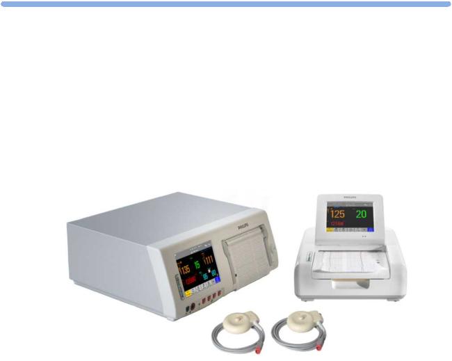
The Avalon family of fetal monitors consists of the Avalon FM20, FM30, FM40 and FM50. While the FM20/FM30 and the FM40/FM50 have different form factors, the method of operation is very similar for all monitors. The Avalon fetal monitors also share the same transducers, accessories, software, and are compatible with the Avalon CTS Cordless Fetal Transducer System (M2720A).
Intended Use
The Philips Avalon FM20 (M2702A), FM30 (M2703A), FM40 (M2704A) and FM50 (M2705A) Fetal/ Maternal Monitors are intended for:
•non-invasive monitoring of fetal heart rates and movements.
•non-invasive monitoring of maternal heart rates, maternal pulse rates, uterine activity, maternal noninvasive blood pressure, and maternal oxygen saturation.
•invasive monitoring of fetal Direct ECG and intrauterine pressure and for displaying and recording of fetal and maternal ECG waves. (FM30 and FM50 only)
•displaying, storing and recording patient data and parameter values and for generating alarms from fetal and maternal parameters.
•transmitting patient data and parameter values to a patient information and surveillance system.
•use by trained health care professionals.
•use in antepartum testing areas, in labor and delivery rooms and during postpartum recovery in the hospital environment. They are not intended for use in intensive care units or operating rooms.
•transport situations in healthcare facilities, for healthcare facilities outside hospitals, such as doctors’ offices, and for use in private households. (FM20 and FM30 only)
WARNING
The fetal/maternal monitors are not intended for:
•use during defibrillation, electro-surgery, or magnetic resonance imaging (MRI).
•ECG measurements on patients connected to electrical stimulators or with cardiac pacemakers.
•use of the invasive measurements IUP and fetal DECG and use of the patient module (M2738A) in domestic establishments and those connected directly to the public low-voltage supply network that supplies buildings used for domestic purposes.
CAUTION
US federal law restricts this device to sale by, or on the order of, a physician.
11

1 Introduction
Indications for Use
Avalon Fetal/Maternal Monitor FM20:
Indicated for use by trained health care professionals whenever there is a need for monitoring of the physiological parameters uterine activity, heart rate, oxygen saturation, non-invasive blood pressure, pulse rate of pregnant women and the fetal heart rates of single fetuses, twins, and triplets in labor and delivery rooms, in antepartum testing areas, in private households and during transports in healthcare facilities.
Avalon Fetal/Maternal Monitor FM30:
Indicated for use by trained health care professionals whenever there is a need for monitoring of the physiological parameters uterine activity, heart rate, ECG, oxygen saturation, non-invasive blood pressure, and pulse rate of pregnant women and the fetal heart rates of single fetuses, twins, and triplets in labor and delivery rooms, in antepartum testing areas, in private households and during transports in healthcare facilities.
Avalon Fetal/Maternal Monitor FM40:
Indicated for use by trained health care professionals whenever there is a need for monitoring of the physiological parameters uterine activity, heart rate, oxygen saturation, non-invasive blood pressure, and pulse rate of pregnant women and the fetal heart rates of single fetuses, twins, and triplets in labor and delivery rooms and in antepartum testing areas.
Avalon Fetal/Maternal Monitor FM50:
Indicated for use by trained health care professionals whenever there is a need for monitoring of the physiological parameters uterine activity, heart rate, ECG, oxygen saturation, non-invasive blood pressure, and pulse rate of pregnant women and the fetal heart rates of single fetuses, twins, and triplets in labor and delivery rooms and in antepartum testing areas.
12

2
Installation
Installation should be carried out by qualified service personnel, either by the hospital's biomedical department, or by Philips Support.
As the first step in preparing the monitor for use, follow the installation instructions given in this chapter.
For a list of conventions used in this guide, see “Basic Operation” on page 19.
Not all accessories and supplies may be available in all geographies. Please contact your local Philips sales representative for details of availability.
Installation Checklist
Use this checklist to document your installation.
Step |
Task |
Check Box |
|
|
when Task |
|
|
Done |
|
|
|
1 |
Perform initial inspection of delivery, unpack and check the shipment |
|
|
(see “Unpacking and Checking the Shipment” on page 14) |
|
|
|
|
2 |
Mount the monitor as appropriate for your installation (see “Mounting |
|
|
the Monitor” on page 15) |
|
|
|
|
3 |
Connect the fetal monitor to AC mains using the supplied power cord. |
|
|
This configuration varies, depending whether an external power |
|
|
supply/battery option is used. (see “External Power Supply M8023A” |
|
|
on page 58) |
|
|
|
|
4 |
Perform Safety Tests (see “Safety Tests” on page 18) |
|
|
|
|
5 |
Check that default settings (including the line frequency) are |
|
|
appropriate for your institution |
|
|
|
|
6 |
Check/set the paper scale (see “Checking/Setting Paper Scale” on |
|
|
page 42) |
|
|
|
|
7 |
Load paper into the recorder (see “Loading Paper: FM20/FM30” on |
|
|
page 44 or “Loading Paper: FM40/FM50” on page 45, depending on |
|
|
your monitor) |
|
|
|
|
8 |
Check/set the time and date (see “Setting the Date and Time” on |
|
|
page 35) |
|
|
|
|
13

2 Installation
Step |
Task |
Check Box |
|
|
when Task |
|
|
Done |
|
|
|
9 |
Check/set paper speed (see “Choosing Paper Speed” on page 48) |
|
|
|
|
10 |
Perform System Test as necessary (see the Service Guide) |
|
|
|
|
11 |
For monitors with the battery option (#E25) chosen, confirm that the |
|
|
battery can be charged, and that the monitor can be powered by the |
|
|
battery. |
|
|
|
|
12 |
Test Transducers (see “Testing Ultrasound Transducers” on page 112 |
|
|
and “Testing Toco Transducers” on page 132) |
|
|
|
|
Unpacking and Checking the Shipment
The monitor and any supporting options ordered are supplied packed in protective shipping cartons.
Initial Inspection
Before unpacking, visually check the packaging and ensure that there are no signs of mishandling or damage.
Open the package carefully and remove the instrument and accessories.
Check that the contents are complete and that the correct options and accessories have been delivered.
System Components, Accessories and Supplies |
FM20 |
FM30 |
FM40 |
FM50 |
|
|
|
|
|
Toco+ Transducer (with belt clip) |
- |
optional |
- |
optional |
Toco MP Transducer (with belt clip) |
1 |
1 |
1 |
1 |
|
|
|
|
|
US Transducer (with belt clip) |
1 |
1 |
1 |
1 |
|
|
|
|
|
Patient Module for DECG/MECG/IUP |
optional1 |
optional |
optional1 |
optional |
DECG Reusable Legplate Adapter Cable |
- |
1 |
- |
1 |
|
|
|
|
|
MECG Adapter Cable |
- |
1 |
- |
1 |
|
|
|
|
|
IUP Adapter Cable2 |
- |
optional |
- |
optional |
External Power Supply and MSL Cable |
optional |
optional |
- |
- |
|
|
|
|
|
Event Marker |
optional |
optional |
optional |
optional |
|
|
|
|
|
Fetal Paper Pack (country-specific, installed) |
1 |
1 |
1 |
1 |
|
|
|
|
|
Powercord |
1 |
1 |
1 |
1 |
|
|
|
|
|
Printed Instructions for Use |
1 |
1 |
1 |
1 |
|
|
|
|
|
Documentation DVD: includes FM20/30 Service Guide, |
1 |
1 |
1 |
1 |
FM40/50 Service Guide, Instructions for Use (including |
|
|
|
|
localized versions), and Training Guide |
|
|
|
|
|
|
|
|
|
1For assessment of maternal heart rate only.
2Ships with Patient Module (K03).
14

2 Installation
Claims for Damage
If the shipping cartons are damaged, contact the carrier.
If any of the equipment is damaged, contact both the carrier and your local Philips service organization for repair or replacement arrangements.
Repacking
Retain the original packing carton and material, in case you need to return equipment to Philips for service. If you no longer have the original packing materials, Philips can advise you on alternatives.
Mounting the Monitor
FM20/30 The monitor can be rested on a flat surface, set at an angle using the built-in stand, or mounted on a wall, on a cart or on a rollstand. See the Service Guide for details.
FM40/50 The monitor can be rested on a flat surface, or on a cart. See your monitor's Service Guide for details.
Mounting the External Power Supply (M8023A)
The external power supply (M8023A option #E25) can be rested on its rubber feet on a flat, level surface, or mounted as described in the Service Guide.
The following pictures show examples of correct  and incorrect
  ways to mount the power supply.
15

2 Installation
Connecting the Monitor to AC Mains
FM20/30 The monitor is an electrical Class II device in which the protection against electric shock does not rely on basic insulation and a protective earth conductor but on double and/or reinforced insulation.
FM40/50 The monitor is an electrical Class I device. Protection against electric shock is provided by a protective earth conductor.
The monitor has a wide-range power supply that allows you to operate the monitor from an AC (alternating current) power source of 100 V to 240 V (± 10%) and 50 or 60 Hz (± 5%).
WARNING
•Always use the supplied power cord with the earthed mains plug to connect the monitor to an earthed AC mains socket. Never adapt the mains plug from the power supply to fit an unearthed AC mains socket.
•Check that the line frequency is correctly set for your institution (50 Hz or 60 Hz) before putting the monitor into service.
•FM20/FM30 only: The protective earth conductor is required for EMC purposes. It has no protective function against electric shock! The protection against electric shock in this device is provided by double and/or reinforced insulation.
•Do not use AC mains extension cords or multiple portable socket-outlets.
16

2 Installation
How and When to Carry Out the Test Blocks
The following table defines which test and inspection blocks need to be performed, and when they are required.
Test Block |
Test or Inspection to be Performed |
Test Block Required for |
|
|
Which Events? |
|
|
|
Visual |
Inspect the monitor, transducers and cables for any |
Installation |
|
damage. |
Preventive Maintenance |
|
Are they free of damage? |
|
|
|
|
|
|
|
Power On |
Power on the monitor. Does it boot up successfully without |
Installation |
|
errors? After boot up the monitor sounds a tone, and can |
Preventive Maintenance |
|
you see the monitoring main screen. |
|
|
|
|
|
If recorder power-on auto-start is configured to On, does |
|
|
the recorder print Selftest: OK across the trace paper? (See |
|
|
“Switching the Recorder On and Off ” on page 49 for |
|
|
details.) |
|
|
|
|
Functionality Test |
FM20/30 with Battery Option #E25 Only |
Installation |
|
After power up, touch the battery status indicator in the |
Preventive Maintenance |
|
bottom right of the screen. The battery status window |
|
|
should open. Check to see if there is an exclamation mark |
|
|
flashing in the gauge. Press the Main Screen key to close |
|
|
the window and return to the main screen. |
|
Safety Tests (1) to (4) |
Perform safety tests (1) to (4), as described in your |
Installation |
|
monitor's Service Guide, for standalone devices if required by |
Preventive Maintenance |
|
local regulations, and each time you combine equipment to |
|
|
form a system, or exchange system components. |
|
|
|
|
Performance |
Test the transducers (see “Testing Ultrasound Transducers” |
Installation |
|
on page 112 and “Testing Toco Transducers” on page 132). |
Preventive Maintenance |
|
|
|
System |
Perform the system test according to IEC/EN 60601-1-1/ |
Combining system |
|
IEC/EN 62353, if applicable, after combining equipment |
components |
|
to form a system (see your monitor's Service Guide). |
|
|
|
|
For test and inspection information regarding repairs, upgrades and all other service events, refer to your monitor's Service Guide.
17

2 Installation
Safety Tests
Details of the safety tests and procedures required after an installation or an exchange of system components are described in your monitor's Service Guide. These safety tests are derived from international standards but may not be sufficient to meet local requirements.
WARNING
•Do not use additional AC mains extension cords or multiple portable socket-outlets. If a multiple portable socket-outlet is used, the resulting system must be compliant with IEC/EN 60601-1-1.
•Do not connect any devices that are not supported as part of a system.
•Do not use a device in the patient vicinity if it does not comply with IEC/EN 60601-1. The whole installation, including devices outside of the patient vicinity, must comply with IEC/EN 60601-1- 1. Any non-medical device, including a PC running an OB TraceVue system, placed and operated in the patient's vicinity must be powered via a separating transformer (compliant with IEC/EN 60601-1-1) that ensures mechanical fixing of the power cords and covering of any unused power outlets.
18
3
Basic Operation
This chapter gives you an overview of the monitor and its functions. It tells you how to perform tasks that are common to all measurements (such as entering data, switching a measurement on, changing some monitor settings, and setting up the recorder). The alarms section gives an overview of alarms. The remaining sections tell you how to perform individual measurements, and how to care for and maintain the equipment.
Supported Measurements
The following Fetal Measurements are supported:
Fetal Monitor |
Fetal Heart Rate |
Triple FHR via |
Toco |
FHR via Direct |
Intrauterine |
or Model |
(FHR) via US |
US |
|
ECG (DECG) |
Pressure (IUP) |
|
(including Twins) |
|
|
|
|
|
|
|
|
|
|
FM20 |
Standard |
Optional |
Standard |
- |
- |
|
|
|
|
|
|
FM30 |
Standard |
Optional |
Standard |
Standard |
Standard |
|
|
|
|
|
|
FM40 |
Standard |
Optional |
Standard |
- |
- |
|
|
|
|
|
|
FM50 |
Standard |
Optional |
Standard |
Standard |
Standard |
|
|
|
|
|
|
19
3 Basic Operation
The following Maternal Measurements are supported:
Fetal Monitor |
Maternal |
Maternal |
Maternal Pulse |
Non-invasive Blood |
Pulse Oximetry |
or Model |
Heart Rate |
ECG |
from Toco |
Pressure with Pulse |
(Maternal SpO2) |
|
(MHR) via |
(MECG) |
|
Rate |
with Pulse Rate |
|
Maternal ECG |
|
|
|
|
|
Electrodes |
|
|
|
|
|
|
|
|
|
|
FM20 |
Standard |
- |
Standard |
Optional |
- |
|
|
|
|
|
|
FM30 |
Standard |
Standard |
Standard |
Optional |
Optional |
|
|
|
|
|
|
FM40 |
Standard |
- |
Standard |
Standard |
Standard |
|
|
|
|
|
|
FM50 |
Standard |
Standard |
Standard |
Standard |
Standard |
|
|
|
|
|
|
Avalon FM20 and FM30
This section outlines the capabilities of your monitor.
Avalon FM20
The Avalon FM20 fetal/maternal monitor provides a solution for external fetal monitoring applications, and optional non-invasive maternal vital signs.
You can monitor fetal heart rates (FHRs) externally using ultrasound, uterine activity and maternal pulse using an external Toco transducer, and the maternal heart rate (MHR) via maternal ECG electrodes, and optionally, non-invasive blood pressure.
Measurements are displayed on a 6.5-inch color display as numerics. The display is a touchscreen, and you operate the monitor using this touchscreen interface. The integrated recorder documents fetal and maternal measurements as well as user defined annotations.
You can connect the monitor to an OB TraceVue system via the RS232 connection, or over a LAN connection (with OB TraceVue Revision E.00.00 and later).
20
3 Basic Operation
Avalon FM30
FM20/30 with Battery Option #E25 Only
The Avalon FM30 fetal/maternal monitor offers a solution for both external and internal fetal monitoring applications, and optional non-invasive maternal vital signs.
The Avalon FM30 shares all the features and capabilities of the Avalon FM20. In addition, you can monitor one FHR internally via direct fetal electrocardiogram (DECG), uterine activity internally using
an intra-uterine pressure (IUP) catheter together with a Toco+ transducer or patient module, and optionally, maternal oxygen saturation (SpO2).
The Avalon FM30 carries the  label, indicating that it is capable of intrapartum monitoring.
The battery option for the FM20/30 provides support for the in-transport monitoring of all measurements when disconnected from a power supply. Existing data storage is automatically uploaded to OB TraceVue after reconnecting to the system. Trace printing during transport is also possible.
Avalon FM40 and FM50
This section outlines the capabilities of your monitor.
Avalon FM40
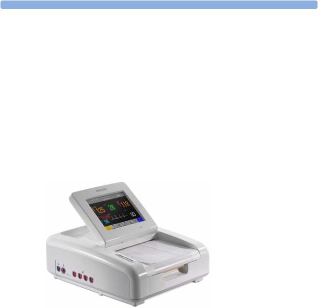
The Avalon FM40 fetal/maternal monitor provides a solution for external fetal monitoring applications, and non-invasive maternal vital signs.
You can monitor fetal heart rates (FHRs) externally using ultrasound, uterine activity using an external Toco transducer, and the maternal heart rate (MHR) via maternal ECG electrodes, and non-invasive blood pressure and maternal oxygen saturation (SpO2).
Measurements are displayed on a 6.5-inch color display as numerics. The display is a touchscreen, and you operate the monitor using this touchscreen interface. The integrated recorder documents fetal and maternal measurements as well as user defined annotations.
You can connect the monitor to an OB TraceVue obstetrical documentation and surveillance system via the RS232 connection, or over a LAN connection (with OB TraceVue Revision E.00.00 and later).
21
3 Basic Operation
Avalon FM50
The Avalon FM50 fetal/maternal monitor offers a solution for both external and internal fetal monitoring applications, and non-invasive maternal vital signs.
The Avalon FM50 shares all the features and capabilities of the Avalon FM40. In addition, you can monitor one FHR internally via direct fetal electrocardiogram (DECG), and uterine activity internally
using an intra-uterine pressure (IUP) catheter together with a Toco+ transducer or patient module.
The Avalon FM50 carries the  label, indicating that it is capable of intrapartum monitoring.
Cordless Monitoring
All monitors are compatible with the Avalon CTS Cordless Fetal Transducer System (M2720A). Note the following points regarding cordless monitoring:
•One Avalon CTS Cordless Fetal Transducer System can be connected to a monitor at a time.
•Monitoring multiple pregnancies using cordless transducers is not supported.
•Using a mixture of wired and cordless fetal transducers is not supported. You can use either wired or cordless fetal transducers. If sufficient signal quality cannot be achieved using cordless fetal transducers, then switching to wired transducers is recommended.
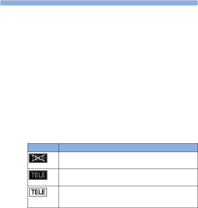
•When the monitor recognizes an Avalon CTS interface cable M2731-60001 (red connector) or M2732-60001 (black connector, for rear connection on FM40/FM50 only), it gives confirmation by showing the following status indicator in the lower right-hand corner of the screen:
Indicator Meaning
Avalon CTS interface cable is connected to the monitor, but the Avalon CTS base station is not connected to the interface cable, disconnected from AC mains, or is in Standby.
Avalon CTS interface cable is connected to the monitor, Avalon CTS base station is connected, powered on, and cordless transducers are ready to use, but no cordless transducers are currently active (all are still docked in the base station).
Avalon CTS interface cable is connected to the monitor, Avalon CTS base station is connected, powered on, and at least one cordless transducer has been taken out of the base station and is active. As cordless transducers have priority over wired transducers, any connected wired transducers are disabled.
•Cordless transducers have priority over wired transducers. When an Avalon CTS base station is connected via the appropriate interface cable to the fetal monitor, and there are also wired transducers connected to the monitor, the wired transducers are disabled whenever a cordless transducer is active. To change back to using wired transducers, dock the cordless transducers in the Avalon CTS base station or switch the base station to Standby, and continue monitoring with the wired transducers. Note that if a sufficient ultrasound signal quality cannot be achieved by transducer repositioning, change to wired transducers.
•When using a cordless ultrasound transducer from an Avalon CTS system, the monitor automatically sets the Fetal Movement Profile (FMP) to Off. You can enable the FMP again should you wish, (see “Switching FMP On and Off ” on page 101), but you should refer to the sections “Cordless Monitoring - Important Considerations” on page 97 and “Fetal Movement Profile” on page 100.
22
3 Basic Operation
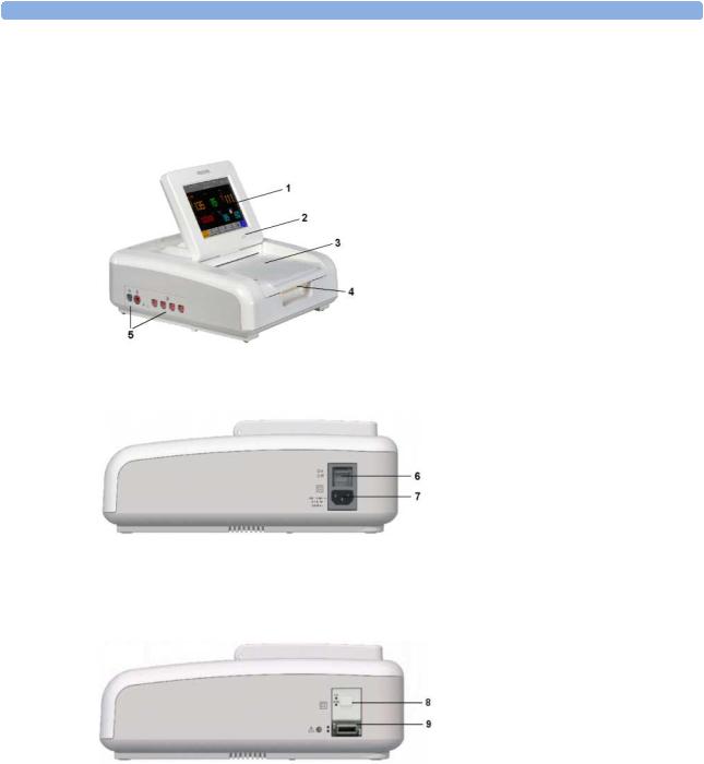
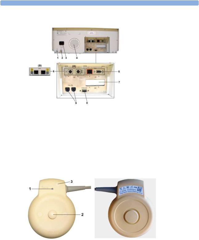
Getting to Know Your Avalon FM20/FM30
Overview
1 Touchscreen Display (tilt and fold)
2 Power LED
3 Paper Drawer
4 Paper Drawer release
5 Connectors (see Left Side view)
Right Side
6 On/Off Switch
7 Power Connector
with Battery Option
8 On/Standby Switch
9 MSL Connector
23
")
3 Basic Operation
Rear
10 Display Release
11 Carrying Handle
12 Built-in Stand
Left Side
13 SpO2 Socket (optional)
14 Noninvasive Blood Pressure Socket (optional)
15 Fetal Sensor Sockets - each socket accepts any fetal transducer, an Avalon CTS Cordless Fetal Transducer System base station (connected via the interface cable M273160001), or event marker
Getting to Know Your Avalon FM40/FM50
Front
1 |
On/Standby Switch |
2 |
Power LED |
3 |
Recorder Paper Table |
4 |
Touchscreen Color Display |
5 |
Transparent Paper Guide with |
|
tear-off edge |
6 |
Paper Eject Button. Press to |
|
open paper drawer. Press again |
|
and hold when removing paper. |
7 |
Fetal Sensor Sockets. Connect |
|
any fetal sensor or patient |
|
module here, including Avalon |
|
CTS via M2731-60001 interface |
|
cable (with red connector). |
8 |
Noninvasive Blood Pressure |
|
Socket |
9 |
SpO2 Socket |
24
3 Basic Operation
Rear
1 |
Reserved for future use: |
|
protective earth intended for use |
|
in system installations. |
2 |
Equipotential Grounding Point |
3 |
Power Cord Connector |
4 |
Loudspeaker |
5 |
Slot 01 for optional LAN / |
|
RS232 system interface (for |
|
connection to an obstetrical |
|
information and surveillance |
|
system) |
6 |
Slot 02 for optional interfaces: |
|
Either dual PS/2 system |
|
interface (A) for mouse and |
|
keyboard connection) |
|
Or MIB interface (B) for |
|
external touch screen |
|
connection |
7 |
Slot 03 reserved for future use |
8 |
Video Output (VGA) |
9 |
Telemetry Interface. If not using |
|
one of the fetal sensor sockets, |
|
one Avalon CTS can be |
|
connected at a time to either |
socket using the M2732-60001 interface cable (with black connector).
Transducers
Toco and Toco MP Transducer (M2734A, M2734B)
1Transducer Finder LED - lights up on the transducer providing the measurement source.
2Belt Button
3"MP" for M2734B "Toco MP" transducers (additionally capable of providing the maternal pulse measurement)
25

3 Basic Operation
Ultrasound Transducer (M2736A)
4 Cable - connects to any of the four Fetal Sensor Sockets on the monitor
Note that the The M2736AA US transducer is identical to the M2736A US transducer, including all specifications.
Toco+ Transducer with ECG/IUP capability (M2735A)
5 Connector - for connecting ECG/IUP adapter cables (M2735A Toco+ transducer only)
6 Butterfly Belt Clip (shown fitted; for use with belts without button holes)
7 Close-up of MECG adapter cable connected to Toco+ transducer
8 Close-up of active Finder LED
26
3 Basic Operation
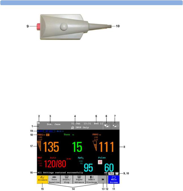
Patient Module for ECG/IUP (M2738A)
9Connector - for connecting ECG/IUP adapter cables (same as for Toco+ transducer)
10Cable - connects to any of the four Fetal Sensor Sockets on the monitor
Operating and Navigating
Your monitor has a touchscreen. Everything you need to operate the monitor, other than to turn it on and off, is contained on its screen. Most screen elements are interactive. Screen elements include measurement numerics, screen keys, information fields, status indicators, alarms fields and menus.
FM40/50 If an optional external touch display with a MIB interface board are connected to the monitor, you can operate the monitor using the external touch display.
Screen Elements
Monitor Information Line
1INOP and alarm status area - shows active alert messages
2LAN connection status indicator only. RS232 system connection is not indicated. Either the Monitor is connected to OB TraceVue  , the LAN cable is connected but no connection to OB TraceVue
  ; or, if no indicator is shown, there is no network connection.
3Patient identification
27

3 Basic Operation
4Date and time
5Bed label (when connected to a Philips OB TraceVue system)
6Fetal heart sound volume adjust/indicator
7Alarm volume adjust/indicator
8Numeric/measurement values
9Fetal Trace Recorder - status indicator Fetal recorder is On
Fetal recorder is Off (when Paper Save Mode is off )
Fetal recorder is Off (when Paper Save Mode is on)
There is a Recorder problem that can be solved by the user (for example, paper out, paper jam, wrong paper scale set)
Fetal recorder is defective: call service.
10Avalon CTS System - status indicator:
Avalon CTS interface cable is connected to the monitor, but Avalon CTS base station is not connected to the interface cable, disconnected from AC mains, or is in Standby.
Avalon CTS interface cable is connected to the monitor, Avalon CTS base station is connected, powered on, and cordless transducers are ready to use, but no cordless transducers are currently active (all are still docked in the base station).
Avalon CTS interface cable is connected to the monitor, Avalon CTS base station is connected, powered on, and at least one cordless transducer has been taken out of the base station and is active. Any connected wired transducers are disabled.
11Close all open menus and windows and return to main screen
12Battery Status Indicator
13Scroll to display more SmartKeys
14SmartKeys - these can vary according to your monitor's configuration
15Silence - key which acknowledges all active alarms by switching off audible alarm indicators
28
3 Basic Operation
16Status line - shows status and prompt messages
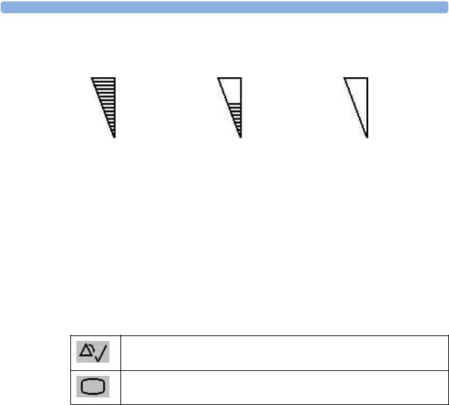
17Signal quality indicator
Good / full |
acceptable / medium |
Poor / no signal |
18Measurement label (a cordless measurement from a connected Avalon CTS system is indicated by the  symbol)
19NST timer, if configured (default is Off)
Keys
The monitor has three different types of keys.
Permanent Keys
A permanent key is a graphical key that remains permanently on the screen, giving you fast access to functions.
Silence - acknowledges all active alarms by switching off audible alarm indicators.
Main Screen - closes all open menus and windows and returns to the main screen.
29

3 Basic Operation
SmartKeys
SmartKeys are configurable graphical keys, located at the bottom of the main screen. They give you fast access to functions. The selection of SmartKeys available on your monitor depends on your monitor configuration and on the options purchased.
|
|
Main Setup - enter main setup |
|
|
Recorder Start/ Stop - turn the trace |
|
|
menu. |
|
|
recorder on or off. |
|
|
|
|
|
|
|
|
Pause Alarms - pauses alarm |
|
|
Paper Advance - advance the paper |
|
|
indicators. Pause duration depends |
|
|
automatically to the next fold. |
|
|
on monitor configuration. If pause |
|
|
|
|
|
duration is infinite, this key is |
|
|
|
|
|
labeled Alarms Off. |
|
|
|
|
|
Select again to immediately re- |
|
|
|
|
|
enable alarm indicators. |
|
|
|
|
|
|
|
|
|
|
|
Start Recordng - turn the trace |
|
|
Stop Recordng - turn the trace |
|
|
|
|
||
|
|
recorder on. |
|
|
recorder off. |
|
|
|
|
|
|
|
|
|
|
|
|
|
|
|
|
|
|
|
|
Start ECG- start printing the |
|
|
Stored Data Rec - print trace data |
|
|
|
|
||
|
|
MECG, DECG or both waves, |
|
|
from the monitor's memory. |
|
|
when both are available. |
|
|
|
|
|
|
|
|
|
|
|
|
|
|
|
|
|
|
|
|
|
|
|
Admit/ Dischrge - enter patient |
|
|
Enter Notes - enter notes |
|
|
identification menu to admit/ |
|
|
|
|
|
discharge |
|
|
|
|
|
|
|
|
|
|
|
Toco Baseline - reset Toco |
|
|
Timer - enters NST timer window |
|
|
|
|
||
|
|
baseline/whichever is available |
|
|
|
|
|
(see below) |
|
|
|
|
|
|
|
|
|
|
|
|
|
|
|
|
|
Zero IUP - zero IUP |
|
|
Set Marker - mark an event |
|
|
|
|
||
|
|
measurement/whichever is |
|
|
|
|
|
available (see above) |
|
|
|
|
|
|
|
|
|
|
|
|
|
|
|
|
|
|
|
|
|
30
 Loading...