


TM
ENGLISH
Product No.77420
HOYA CORPORATION
PENTAX Imaging Systems Division
Technical Service Group
11.10 N.T
[TABLE OF CONTENTS] |
|
PREPARATION ------------------------------------------------------------------------------------------- |
2 |
Preparation of Adjustments -------------------------------------------------------------------------------- |
2 |
Outline of Assembly and Disassembly ----------------------------------------------------------------- |
6 |
1. Caution ---------------------------------------------------------------------------------------------------- |
6 |
2. Flow chart for assembling body and Front housing ------------------------------------------------- |
6 |
3. [IV. Confirmation/ Adjustment] Flow ----------------------------------------------------------------- |
7 |
Assembly and Disassembly --------------------------------------------------------------------- |
8 |
I. Disassembly procedure of main body ----------------------------------------------------------------- |
8 |
II. Assembly and disassembly procedure of front housing block ------------------------------------ |
19 |
III. Assemble procedure of main body ------------------------------------------------------------------- |
32 |
IV. Adjustment and Confirmation ------------------------------------------------------------------------ |
55 |
FW FIRMWARE ------------------------------------------------------------------------------ |
95 |
1. Method for Checking FW version --------------------------------------------------------------------- |
95 |
2. Method for Updating Firmware Version -------------------------------------------------------------- |
95 |
TECHNICAL INFORMATION ----------------------------------------------------------------------------- |
97 |
Battery consumption current ------------------------------------------------------------------------------ |
97 |
Block diagram ----------------------------------------------------------------------------------------------- |
98 |
Table of Error Code 1 (SR unit adjustment) ------------------------------------------------------------ |
100 |
Table of Error Code 2 (SR gain adjustment) ------------------------------------------------------------ |
100 |
Table of Error Code 3 (Uniformity AF adjustment) ------------------------------------------------- |
101 |
Table of Error Code 4 (FI AF adjustment) -------------------------------------------------------------- |
101 |
Table of Error Code 5 for Digital adjustment ----------------------------------------------------------- |
102 |
Table of Error Code 6 for Digital adjustment (Writing Warranty record) --------------------------- |
104 |
Information of Jigs, Tools and Testers ------------------------------------------------------------------- |
105 |
Method for making temporally bottom cover ----------------------------------------------------------- |
105 |
Chart for SR Gain adjustment ---------------------------------------------------------------------------------- |
106 |
AF confirmation chart and scale Ver.2 ------------------------------------------------------------------- |
107 |
77420 - 1/107 -
PREPARATION
The following preparations are required before disassembling and assembling the camera.
1.Prepare the Jigs; tools and testers (Refer to the table of Jigs, tools and testers.)
2.Make the preparation for adjustment with referring [Preparation of Adjustments].
Preparation of Adjustments
[Required equipment]
Programmed software for 77420(CD-ROM) |
|
|
Computer (PC) |
|
|
OS: Windows XP SP2 |
CPU: 1GHz or more |
RAM: 512MB or more |
Free disk space (HD): 500MB or more
SD card 5 pieces (16Mb or above) --- for FW
SD card reader or USB cable (I-USB17) --- For connecting with PC
1. Prepare SD card (5 pcs) for confirming adjustment
*prepare SD card (5pcs)
1.For Product FW (Firmware)
2.For writing Initial Data
3.For Initial set (Initialize / Product shipment)
4.For test mode ON / OFF (For confirming full version, 1 pcs each)
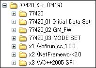
2. Installing procedure of the Adjustment Software (Setting of the Computer)
*Set programmed software for 77420 (CD-R) to CD-ROM drive.
Copy the [77420] folder from the programmed software contained in the CD-ROM to [C: drive]Copy the file from [GM_FW] folder to SD card --- For Product FW (Firmware)
Copy the 2 files from [Initial Data Set] folder to SD card. --- For writing Initial Data.
Copy the file from [Initial Set] folder in the [MODE SET] to SD card.--- For Initial set (Initialize)
Copy the file from [Test mode ON] and [Test mode OFF] folder in the [MODE SET] to each SD card. (Since the name of all files is the same, you should distinguish them by name label etc.)
77420 - 2/107 -
3. Installing software
[Important] Install below 3 kind of software (The same as 77010:K20D and 77050:K200D)
1.Net Framework Ver2.0 (Common with 77010 and 77050. It is not required if the software is already installed)
2.VC++2005 SP1 (Common with 77010 and 77050. It is not required if the software is already installed)
3.VB Runtime (Common with other product. It is not required if the VB Runtime is already installed)
* Set Programmed software for 77420 (CD-R) to CD-ROM drive.
Select [dotnet.exe] from the [NetFramework2.0] folder in CD-ROM then double click icon. Installer will be started up and follow the instruction on the screen and continue with the installation.
Select [vcredist_x86.exe] from the [VC++2005 SP1] folder in the CD-ROM then double click icon. Installer will be started up and follow the instruction on the screen and continue with the installation.
If [VB Runtime] is not set up to your PC yet, select [setup.exe] from the [vb6run_cs_xxx] folder in CD-ROM then double click icon. Installer will be started up and follow the instruction on the screen and continue with the installation. (Refer to the service manual for 76700 for details)
4. Calibration of light source for Digital adjustment
[Important] Execute Calibration of light source before 77420 Digital adjustments.
When replaced the program software, replaced light source or replaced AE master lens, it is required calibration. (Refer to the service manual for 76830 K10D for calibration procedure)
[Required equipment]
K10D Master body for calibration (HOYA Corporation will rend the master body. Please contact with us) Digital adjustment software for 77420 (M-test)
Computer (Windows Xp, support USB), Light source (Example: LB3300, A light source) Master lens for 76180 (D20 or D20-01), and F8 set ring
*Use the same master lens as the ID number printed on CD-ROM to adjust it accurately.
USB cable, AC adaptor for 76830, Dark curtain, Color temperature tester (for calibrate light source), LV meter (for check LV value)
4-1. setting for computer
Complete the [2. Setting for computer] of [PREPARTAION]. (Use software for Digital adjustments)
4-2. Calibration of light source
Before calibration, turn ON the light source and leave 30 minutes for stabilizing light source.
Calibrate Color temperature and Brightness by using color meter and LV checker as shown below table.
Light |
Brightness |
Color |
source |
|
temperature |
LV12 |
LV12.00Ev ±0.50 |
2,856K ±30 |
*Calibrate with using the master body according to the following procedure.
77420 - 3/107 -
4-3. Setting for Master body and Master lens
Set the mode dial to [M].
Set the focus mode lever to [MF].
Set SR function [OFF].
Attach the master lens and F8 set ring to the body.Set the master lens aperture to [F8 position]
4-4. Procedure for calibration
Connect the AC adaptor to the master body.Connect to PC with USB cable.
Turn ON the power and confirm that the camera is recognized by PC.Set the light source to [LV12].
Surely set the camera and lens toward center of light window and cover the whole camera and light window by using a dark curtain
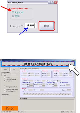
Double crick the adjusting software[K-r_ SLR_MTest.exe] in [K-r_ MTest] folder to start-up.On first screen, select [Adjust All] and input the lens ID number correctly then click [Enter].
When below screen is displayed, click around the title in blue frame to change calibration mode.
77420 - 4/107 -
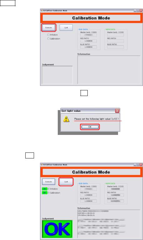
Click Execute on calibration mode to start calibration.
Confirm the light source is set at LV12 then click OK to execute. (Shutter will be released 15 times)
When calibration is completed, OK screen will be displayed.Click [X] button or Quit to finish adjustment software.
* If adjustment is NG, refer to [table of error code].
77420 - 5/107 -
Outline of Assembly and disassembly
1. Caution
1.Be sure to use the anti-static mat and wrist strap to prevent static failure of circuits.
2.This product is used lead free solder.
Surface of solder will be white-tinged color. Solder quickly, because melting temperature is high and so if
heat too much, it is possible to damage to PC board. Soldering iron requirement: The temperature can be adjusted up to 400 and exclusive use for lead free solder. Also it is desirable to use antistatic soldering iron. The temperature for tip of soldering iron must set between 340 360 for lead free solder.
3. Do not stress to the connector terminals and flexible boards because they are very delicate parts. Pay careful attention to the connector terminals and flexible boards and, we recommend marking to the flexible board before disconnecting them. This will be helpful to reconnect the flexible board to the connector terminal properly.
2. Flow chart for assembling body and Front housing
III. Assembling body
1.E100 (Shutter block)
2.A13 (Battery chamber)
3.0-A101 (Front housing block)
4.A6/A19 (Left upper plate, other)
5.T700 (Upper flex circuit board)
6.A4/Q200 (Right front plate/Flash board)
7.T901 (Low flex board)
8.A3 (bottom plate)
9.0-A51 (Tripod plate)
10.Lead wires (bottom)
11.[Conf] Height of SR block Base Plate Support Pillar
12.0-C000 (SR Block)
13.[Adj] Height of 0-C000
14.T100 (Main PC board)
15.Soldering lead wire on T100
16.[Adj] Position of J100
17. 311
18.A150/A201 (Front cover/ Back cover)
19.A301 (Top cover)
20.A401 (Bottom cover) – Temp cover for Adj
21.[Adj] AF-SENSOR POSITION
II. Front housing block
1.Front housing block
2.A104 (Mount ring)
3.0-B52 (Mirror sheet)
4.B11/B20 (Mirror adj parts)
5.[Adj] Positioning 1st and 2nd Mirror
6.G100 (Diaphragm control block)
7.[Conf] Mirror function
8.S300 (AF motor)
9.[Conf] AF Joint stroke
10.0-L101 (Pentamirror)
11.L2 (Fresnel lens)
12.M301(Eyepiece frame)
13.[Conf] Viewfinder focus and parallax
14.O100 (LCD in Viewfinder)
15.[Adj] Viewfinder LCD (0-O100)
16.M100(AF block)
17.J100 (Photo sensor block)
18.M51/O170 (SI block)
19.[Adj] Positioning SI-LED
[IV. Adjustment/Confirmation]
77420 - 6/107 -

3. [IV. Confirmation/ Adjustment] Flow
|
|
|
■General check ■Must execute when replace T100 |
|
1. Battery consumption check |
|
■Optional |
|
|
|
|
|
|
|
|
2. Initialize when replace T100 *Writing Product firm ware [GM_FW] *Writing initial Data [Initial Data Set]
3.SR adjustment I (SR unit adjustment) [SR_Operation_Adjustment]
4. Function Check 1 AF check
Exposure mode/Shutter release Capture/Playback
Flash [Adj]Flash retract position
Diaphragm control/CMOS surface
5. SLR function adjustment [K-r_ PDCAdj] [K-r_ SLR_Uni] [K-r_ SLR_FI]
6. Digital part adjustment [K-r_ MTest]
7. SR adjustment II (SR gain adjustment) [K-r_SR_Gain]
8. Shutter speed adjustment by histogram [K-r_PDCAdj]
Image Shift adjustment [Roration&Shift]
WDC adjustment [K-r_ MTest]
FW (Firmware) (Confirm version/Version up)
9. Writing Warranty Record When replace T100 or serial number
[Warranty_Record]
10. Function check 2 Metering Exposure
WB
AF check by taking picture SR Function
(If already adjusted SR, not necessary) CMOS Cleaning
Initial setting [Initialize Set]
77420 - 7/107 -
Assembly and Disassembly
I. Disassembly procedure of main body
[Preparation] Remove the Hot shoe cover and Eye cap from the main body.
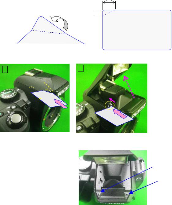
1. POP-up the built-in flash
For removing top cover, install the batteries to the camera and turn on the camera then pop-up the flash by pressing pop-up button.
*If the camera does not pop-up the flash.
[Preparation] Use flash pop-up tool as shown in follow.
(The same tool as MZ-7) --- Use such as thin magnetic card and processes it as follow.
10
5 
Procedure for pop-up.
|
|
|
|
|
|
|
|
|
Unscrew U2 x2 (CNL-D 1.7x4.0)
77420 - 8/107 -
2. Removing A401
[CAUTION] There is strong magnet in the CCD/SR blocks therefore please do not place a screw or magnetic card near the camera after outside cover is removed.
Open the battery cover. |
|
|
|
|
|
|
|
|
|||
Unscrew U4 (1.7x7.0) |
|
|
|
||
|
|
|
|
|
|
|
|
|
|
|
|
Unscrew A34 x3 (1.7x5.0) |
|
|
|
|
|
Unscrew A255 x2 (1.7x4.5) |
|
|
|
|
|
Unscrew A185 x2 (1.7x3.5) |
|
|
|
|
|
Unscrew A191 x2 (1.7x6.0) |
|
|
|
|
|
A401 |
|
|
|
|
|
|
|
|
|
|
[CAUTION] Do not make impact to SR/CCD block on bottom side as shown in figure below.
77420 - 9/107 -

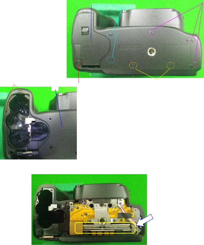
3. Removing top cover (0-A301)
Unscrew A68 x2 (1.7x6.0)
Unscrew A196 (1.7x8.0)
Unscrew A255 (1.7x4.5)
Unscrew A187 (1.7x5.0)
Unscrew TY-CNL-D1.7x4.5 Ni In the battery box
[CAUTION] Be careful the electric shock where flash circuit board is inside the cover.
Discharge the main capacitor.
*Rift up the A301 and discharge the main capacitor by using 100Ω-1kΩ resistor.
(Discharge between Blue and Black soldering land on T750.)
100 1kΩ
Disconnect T50 (Flip lock) and peel off the double-stick tape. |
|
|
|||
Unsolder lead wire x6 |
|
Yellow, White |
|||
A301 |
|
|
|
|
|
|
|||||
|
|
|
|
||
|
|
|
|
||
|
|
|
|
|
|
Black
Blue
77420 - 10/107 - |
Green, Brown |

4. Removing A150 and A201
Set the AF mode lever to [AF]
Peel off the G rubber (A161) and unscrew (CNL-D 1.7x4.0 x2)
Peel off the G rubber (A151) and unscrew (TY-CNL-D 1.7x4.5 x2)The bottom side of camera, unscrew (TY-CNL-D 1.7x4.0)
Unsolder lead wire x2 (Red, Black
A150 --- Remove A150 while lifting side of grip part as shown in figure below.
Black
Red

A201 --- Remove A201 while lifting side of both as shown in figure below.
Disconnect T920 (Plug-in)
77420 - 11/107 -
Unscrew CNL-D1.7x3.0 x2
M311

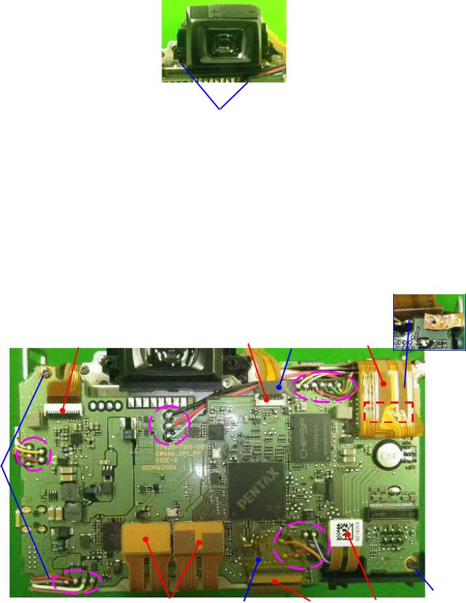
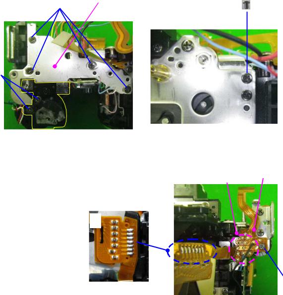
5. Removing 0-T100
Peel off PI tape (U3 (13x17))
Peel off PVF tape (A38 (3.8x10))
Disconnect flexible board (2 positions Flip lock
Disconnect flexible board (4 positions Plug-in
[CAUTION] The flex from CCD block should be taken care (no stress, no bend), otherwise it will affect the performance of CCD.
Unsolder lead wire x24 |
|
|
|
|
|
Unscrew CNL-D 1.7x2.5 x3 |
|
|
|
|
|
|
||
|
Unscrew TY-CNL-D 1.7x3.5 |
|
|
|
|
|
|
||
T100
|
|
|
|
|
|
|
|
||
|
|
|
|
|
|
|
|
|
|
|
|
|
|
|
|
||||
|
77420 - 12/107 -

6. Removing 0-C000 (SR block)
[Requires equipment] Hexagon wrench 1.5mm
[CAUTION 1] Pay attention, there is powerful magnet is carried in the SR block.
[CAUTION 2] Since performance can be damaged, the SR block cannot be disassembled and also don’t apply the external pressure to a movable part.
[CAUTION 3] The flex from SR block should be taken care, otherwise it will affect the performance of SR function.
Disconnect T640 with care. (Plug-in) *Do not damage on T640.
Remove the glue with using tools. (3 Points) --- Peel off part of glue by tool then turn screw.
|
|
|

A31 Adjusting screws x3 by using Hexagon wrench 1.5mm.0-C000 --- Do not scratch on surface of sensor.
A22 Coil springs x3. |
|
|
|
||
|
|
77420 - 13/107 -
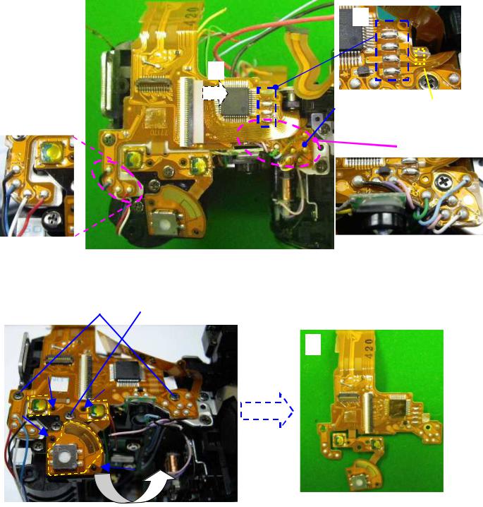
7. Removing T700
Disconnect O100 flex from connector. (Flip lock)
Peel off PI tape (T89)Unsolder lead wires x12
Unsolder flex 4 lands on T71 (G100)

|
|
DT3x4 |
|
|
|
|
|
|
Unscrew CNL-D1.7x1.6 x2 |
|
|
Unscrew TY-CNL-D1.7x2.5 |
|
|
T700 |
|
|
|
||
77420 - 14/107 -
8. Removing A6, A19
Unscrew TY-CNL-D1.7x4.0 x2
A19 |
|
|
Unscrew TY-CSM1.7x4.0 x4 |
|
|
Unscrew CNL-D1.7x2.5 |
|
|
A6 |
|
|

9. Removing T750 (Strobe flex board)
Unscrew CNL-D 1.7x3.0
Unsolder flex 7 lands on O170 |
|
Unsolder lead wires x4 |
|
T750 |
|
77420 - 15/107 -
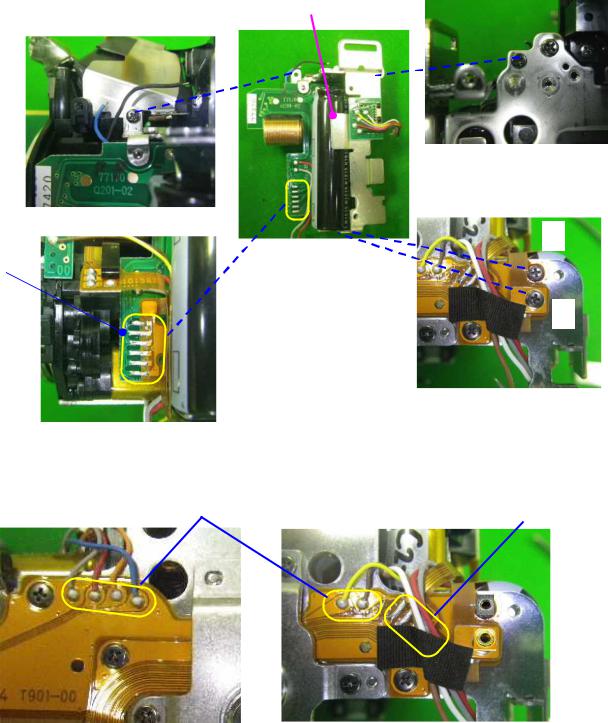
10. Removing A4,Q200 (Right front plate, Strobe circuit block)
Unscrew TY-CNL-D1.7x4.0 |
|
|
|
Unscrew CNL-D1.7x2.5 |
|
|
|
Unscrew CNL-D 1.7x1.6 |
|
|
|
Unscrew CNL-D 1.7x2.2 |
|
|
|
Unsolder flex 6 lands |
|
|
|
Q200 |
|
|
|
|
|
|
|
|
|
|
|
|
|
|
|
|
|
|
|
|
|
|
|
|
|
|
|
11. Unsolder lead wires (Bottom side)
Peel off BT
Unsolder lead wires x6
Unsolder flex 4 lands |
|
|
|

77420 - 16/107 -
12. Removing 0-A51 (Tripod plate assy.)
Unscrew CNL-D1.7x2.2 x30-A51
Unscrew CNL-D1.7x1.6 x3
13 Removing A3 (Bottom plate)
Unscrew CNL-D1.7x2.5 x2
Unscrew TY-CNL-D1.7x4.0 x3A3
14 Removing T901 (Lower flex board)
Unsolder flex 22 lands (T301, M100)T901
Unscrew TY-CNL-D1.7x3.5A141
X58

77420 - 17/107 -

15 Removing 0-A101 (Front housing assy.)
Set the mirror seat top position before removing G100.
Apply DC 2V to 0-S250 and set the mirror seat at top position. (Red lead wire with +)
Unscrew TY-CNM2.0x5.0 x5
0-A101
16. Removing A13 and related parts
Unscrew TY-CNL-D1.7x4.0 x2A13 and related parts

17. Removing E100 (Shutter block)
Unscrew A70 x3E100
Master plate (Not supply
|
|
|
|
|
77420 - 18/107 -
II. Assembly and disassembly procedure of front housing block
*Disassemble the front housing block in reverse of assembly procedures.
*Some pictures are using previous model but basic structural is the same as K-r.
[Assembly]
1. Front housing block
B65
B41, 0-M120 (DT(4x15))
M7 --- Confirm that the surface of lens is clean.
Bond |
|
B65 |
|
|
|
|
0-M120 B41 |
|
M7 |
||
|
2 A104
0-A121 |
|
|
|
|
A133 |
|
|
|
|
|
|
|
G134 |
|
TY-CNL-F1.4x4.0 |
|
|
||
|
|
|
||
|
|
|
||
|
|
|
|
|
|
|
|
|
|
0-A126 and related parts. Apply G134 as shown in figure.
TY-CNL-D1.7x3.0
A105 --- Apply G134 as shown in figure.
A110
0-A108 --- Apply G134 to two shaft part.
G134
G134

G134
77420 - 19/107 -
|
|
|
A104 |
|
|
|
|
|
TY-CNS2.0x4.5Ni x5 |
|
|
*Tighten screw diagonally as shown in figure. |
|
3 0-B52
B58 x2 --- [Temporary position] Installing position as shown in figure below.
B59
TY-CNL-G1.7x2.0
0-B52 (mirror sheet)
B66 (shaft) --- Apply L115 at both side of B66 as shown in figure below. Apply Daia bond (black) to fix 0-B52 as shown in figure below.
B63
B57
B62 (spring) --- Apply screw lock.

|
|
|
10mm |
SL |
|
L115 |
L115 |


Bond
4 B11 B20
Apply G126 (5 positions) and L115 (2 positions) as shown in figure.
Install B20 to B11. |
|
G126 |
|
||
|
|
|
L115 |
|
|
|
|
|
|
|
|
|
|
77420 - 20/107 -
|
|
B11 --- Hook the spring to shaft of mirror seat. |
|
[CAUTION] Caution for come off spring. |
|
B19 |
|
B70 --- Push up 1st mirror then |
|
Surely install B70 as shown in figure. |
|
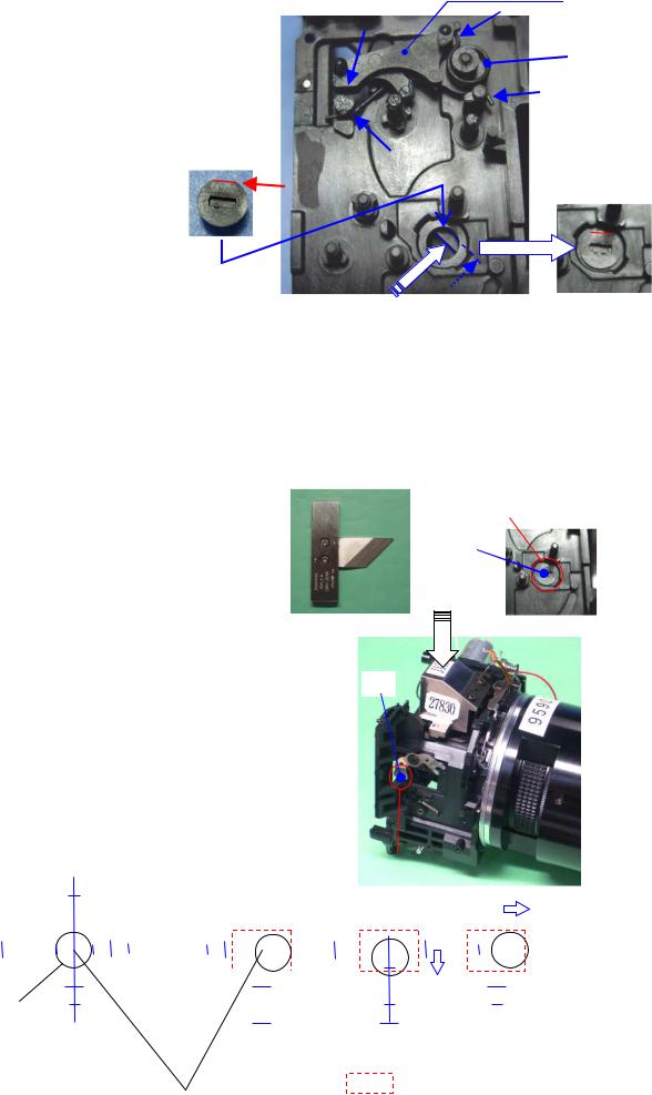
5. [Adjustment] Positioning 1st and 2nd mirror
[Required equipment] 1st mirror angle (45°) adjustment tool,
Mirror angle adjusting for 27830 (need modify), Mirror positioning scope.
*Adjustment is performed by turning B70 and B58 (1 pcs). The Y-axis (the vertical direction) is adjusted to a 0 target.
*Front housing must set mirror down position.
Position 1st mirror : Put the 1st mirror angle (45°) adjusting tool on the camera, and then adjust the mirror seat so that the adjusting tool touches the mirror without gap.
|
|
1st mirror |
|
Tolerance --- X-axis: ±10’ |
|||
|
|
||
Y-axis: ±10’ |
B70 |
||
|
|
|
|
Positioning 2nd mirror : Attach the mirror positioning scope and the 2nd mirror angle adjusting tool to the camera, and then
adjust the mirror angle while looking through the eyepiece lens.
|
|
|
|
|
|
|
|
|
|
|
|
|
|
|
|
|
|
|
|
|
|
|
|
|
|
|
|
|
|
B58 |
|
|
|
|
|
|
|
|
|
|
||||||||
|
Tolerance --- X-axis: ±0.3mm |
|
|
|
|
|
|
|
|
|
|
|
|
|
|
|
|
|
|
|
|
|
|
|||||||||||||||||||||||||
|
|
|
|
|
|
|
|
|
|
|
|
|
|
|
|
|
|
|
|
|
|
|
|
|
|
|
|
|
|
|
|
|
|
|
||||||||||||||
|
|
|
|
|
|
|
|
|
Y-axis: ±0.1mm |
|
|
|
|
|
|
|
|
|
|
|
|
|
|
|
|
|
|
|
|
|
|
|
|
|
|
|
|
|
|
|
|
|
|
|||||
|
|
|
|
|
|
|
|
|
|
|
|
|
|
|
|
|
|
|
|
|
|
|
|
|
|
|
|
|
|
|
|
|
|
|
|
|
|
|
|
|
|
|
|
|
|
|||
|
(Refer to below tolerance for positioning scope) |
|
|
|
|
|
|
|
|
|
|
|
|
|
|
|
|
|
|
|
|
|
|
|||||||||||||||||||||||||
■ Tolerance for 2nd mirror position |
|
|
|
|
|
|
|
|
|
|
|
|
|
|
|
|
|
|
|
|
|
|
|
|
|
|
|
|
|
|
|
|
|
|
||||||||||||||
(Using with the mirror positioning scope) |
|
|
|
|
|
|
|
|
|
|
|
|
|
|
|
|
|
|
|
|
|
|
|
|
|
|
|
|
|
|
||||||||||||||||||
|
|
|
|
|
|
|
|
|
|
|
|
|
Scale |
|
|
|
|
|
|
|
|
|
|
|
|
|
|
|
|
2nd mirror |
|
|
|
|
|
|
|
|
|
|
|
|||||||
|
|
|
|
|
|
|
|
|
|
|
2 |
|
|
|
|
|
|
|
|
2 |
|
|
|
|
|
|
|
|
|
|
|
|
|
|
|
|
|
|
|
|
|
NG: 0.8(X) |
||||||
|
|
|
|
|
|
|
|
|
|
|
|
|
|
|
|
|
|
|
|
0.6 (Y) or over |
|
|
|
|
|
|
|
|
||||||||||||||||||||
|
|
|
|
|
|
|
|
|
|
|
|
|
|
|
|
|
|
|
|
|
|
|
|
|
|
|
||||||||||||||||||||||
|
|
|
|
|
|
|
|
|
|
|
|
1 |
|
|
|
|
|
|
|
|
|
|
|
1 |
|
|
|
|
|
|
|
|
|
|||||||||||||||
|
|
|
|
|
|
|
|
|
|
|
|
|
|
|
|
|
|
|
|
|
|
|
|
|
|
|
|
|
|
|
|
|||||||||||||||||
|
|
|
|
|
|
|
|
|
|
|
|
|
|
|
|
|
|
|
|
|
|
|
|
|
|
|
|
|
|
|
|
|
|
|
|
|
|
|
|
|
|
|
or over. |
|||||
|
|
|
|
|
|
|
|
|
|
|
|
|
|
|
|
|
|
|
|
|
|
|
|
|
|
|
|
|
|
|
|
|
|
|
|
|
|
|
|
|
|
|
|
|
|
|
||
|
|
|
|
|
|
|
|
|
|
|
|
|
|
|
|
|
|
|
|
|
|
|
|
|
|
|
|
|
|
|
|
|
|
|
|
|
|
|
|
|
|
|
|
|
|
|
|
|
|
|
|
|
|
|
|
|
|
|
|
|
|
|
|
|
|
|
|
|
|
|
|
|
|
|
|
|
|
|
|
|
|
|
|
|
|
|
|
|
|
|
|
|
|
|
|
|
|
|
|
|
|
|
|
|
|
|
|
|
|
|
|
|
|
|
|
|
|
|
|
|
|
|
|
|
|
|
|
|
|
|
|
|
|
|
|
|
|
|
|
|
|
|
|
|
|
|
- 2 - 1 |
|
|
|
1 |
2 |
|
- 2 - 1 |
|
|
|
|
1 |
2 |
|
|
|
|
|
|
|
|
|
|
|
|
|
|
|
|
|
|
|
|
|||||||||||||||
|
|
|
|
|
|
|
|
|
|
|
|
|
|
|
|
|
|
|
|
|
|
|
|
|
|
|
|
|||||||||||||||||||||
1mm hole |
- 1 |
|
|
|
|
|
|
|
|
- 1 |
|
|
|
|
|
|
|
|
|
|
|
|
|
|
|
|
|
|
|
|
|
|
|
|||||||||||||||
|
|
|
|
|
|
|
|
|
|
|
|
|
|
|
|
|
|
|
|
|
|
|
|
|
|
|
|
|||||||||||||||||||||
|
|
|
|
|
|
- 2 |
|
|
|
|
|
|
|
|
|
|
|
|
|
|
|
|
|
|
|
|
|
|
|
|
|
|
|
|
|
|
|
|
|
|
|
|
||||||
|
|
|
|
|
|
|
|
|
|
|
|
|
|
- 2 |
|
|
|
|
|
|
|
|
|
|
|
|
|
|
|
|
|
|
|
|
|
|
|
|||||||||||
|
|
|
|
|
|
|
|
|
|
|
|
|
|
|
|
|
|
|
|
|
|
|
|
|
|
|
|
|
|
|
|
|
|
|
|
|
|
|
|
|
|
|||||||
|
|
|
|
|
OK |
|
|
|
|
|
|
OK |
|
|
|
|
NG |
NG |
||||||||||||||||||||||||||||||
|
|
|
|
(Standard) |
|
|
|
|
|
|
|
|
|
|
|
|
|
|
|
|
|
|
|
|
|
|
|
|
|
|
|
|
|
|
|
|
|
|
|
|
||||||||
|
|
|
|
|
|
|
|
|
|
|
|
|
|
|
|
|
|
|
|
|
|
|
|
Tolerance of 1mm hole |
||||||||||||||||||||||||
|
|
|
|
|
|
|
|
|
|
|
|
Center of Standard |
|
|
|
|
|
|
|
|
|
|
|
|
|
|
||||||||||||||||||||||
|
|
|
|
|
|
|
|
|
|
|
|
|
|
|
|
|
|
|
|
|
|
|
|
|
|
|
(X-axis = ±0.8, Y-axis=±0.6) |
|||||||||||||||||||||
|
|
|
|
|
|
|
|
|
|
|
|
|
|
|
|
|
|
|
|
|
|
|
|
|
|
|
|
|
|
|
|
|
|
|||||||||||||||
|
|
|
|
|
|
|
|
|
|
|
|
|
|
|
77420 |
- 21/107 - |
|
|
|
|
|
|
|
|
|
|
|
|
|
|
|
|
|
|
|
|
|
|||||||||||
|
|
|
|
|
|
|
|
|
|
|
|
|
|
|
|
|
|
|
|
|
|
|
|
|
|
|
|
|
|
|
|
|
|
|
|
|||||||||||||

After adjusting and confirming, apply Super-glue as shown in figure.
 Super-glue
B71, B72 --- Surely affix without any gap.
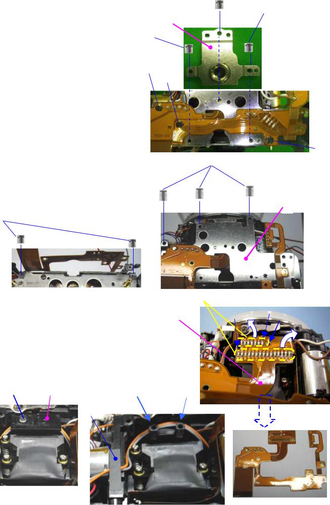
6. 0-G100
Apply G126 (8 points) as shown figure.
G126 |
[CAUTION] Caution for come off spring.B10
B21


Install B17 to B9. |
|
|
|
Install B18 and B9. |
|||
|
|
77420 - 22/107 -
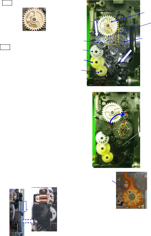
0-B8 (gray)
---Apply G126 to surface of cam.
B7
---Apply G126 to surface of cam on both sides.Align the both hole of 0-B8 and B7.
B3B4B5
B6
|
|
|
|
|
|
|
|
|
|
|
|
Turn B7 clockwise until the arrow indicated in figure right.

Clean code plate by solvent and apply |
G151. |
|
|
||||
Latch the lever of G100 while pushing down the sliding plate. |
|
||||||
|
|
|
|
|
|||
|
|
|
|||||
|
|
|
|
|
|
|
|
|
|
|
|
|
|
|
|
77420 - 23/107 -
0-G100 |
|
--- Surely install G100 without any gap between plates. |
|
TY-CNL-D1.7x3.0 (x4) |
|
Arrange the lead wires with DT(5x5) as shown in figure. |
|

Pink (45mm)
Purple (50)
Red (65mm)
Black (75)
[Arrangement when replace 0-S250]
1.Affix 76140-A61 and DT (7x10) on the mirror motor as shown in figure.
2.Affix S364 on the mirror motor by DT (5x7) and apply super-X (B).
S364 |
|
|
Super-X(B) |
U3 |
|
DT(7x10) |
||
|
||
DT(5x7) |
|
[Notice for disassembly] Set the mirror sheet at top position before removing 0-G100
1.As shown in a figure, a gear is turned, and it sets to a mirror up position.
Mirror up: (Shutter charge lever (1) and mirror sheet (2) and sliding plate (3) must be top end position.)
2.Latch the lever of G100 while pushing down the sliding plate.
3.Remove G100


77420 - 24/107 -

7. [Confirmation] Checking the mirror function
[Required equipment] Power supply
Confirm the following points while applying DC 2V to the mirror motor. (Red wire: Positive) -1) The mirror seat must be moved smoothly without noise.
-2) The shutter charge lever (b) and sliding plate (a) must be moved smoothly and surely go up and down.
Set the mirror seat to the down position while applying DC1.5V. (Fine adjustment is possible when turn white gear at behind of G100.)
Mirror down: mirror, sliding lever, shutter charge lever at down position.
White gear must be positioned as shown in figure. ( )
a |
|
|
|
|
|
||
|
b
Both mirror seats 1st and 2nd must be returned smoothly to the original position when both mirror seat are passed inward about 3mm by finger pressure.
Set the mirror seat to the down position.
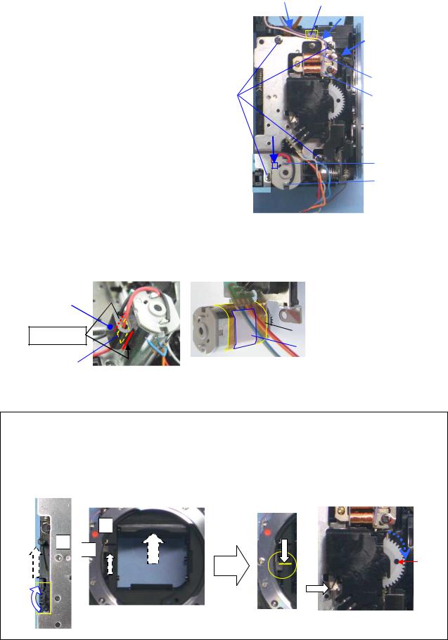
8. 0-S300
Arranged lead wire from motor and S364 as shown in figure and then attach 0-S300.TY-CNL-D1.7x3.5
TY-CNL-D1.7x5.5Apply screw lock.
|
S364 |
|
|
|
DT(5x15) |
0-S300
SL

T940
TY-CNL-D1.7x3.0
A115
TY-CNL-G1.7x2.5


77420 - 25/107 -

9. [Adjustment] AF Joint stroke.
[Required equipment] Vernier calipers
Set the AF lever (0-A115) to the AF.C position.
AF coupler (0-S300) must be projected from the mount surface by 1.2mm or more.
When the mount lock pin comes to the mount surface with pressing the mount lock lever, the AF coupler
must not be projected out of the mount surface.
Adjust 0-A121 by turning an eccentric screw, |
|
and apply the screw lock. |
|
|
SL |
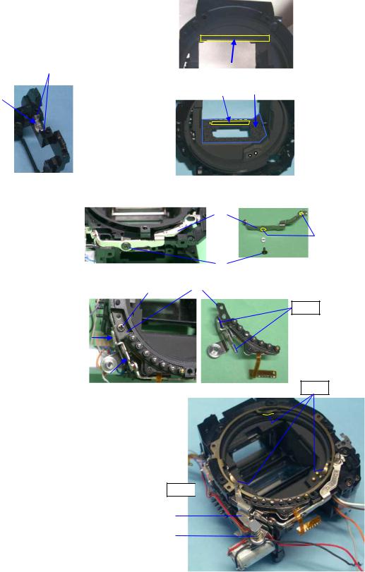
10. 0-L101
[CAUTION] Confirm there is neither dust nor scratch on 0-L101
M3
0-L101 --- Apply Super X (black) to three places.
|
|
|
Super-X(Black) |
|
|
|
||
|
|
|
|
|
|
|||
|
|
|
|
|
|
|
|
|
|
|
|
|
|
|
|
|
|
|
|
|
|
|
|
|
|
|
|
|
|
|
|
|
|
|
|
|
|
|
|
|
|
|
|
|
|
|
|
|
|
|
|
|
|
M9 (M12 x2) |
|
|
[CAUTION] Confirm that three legs are not bent |
||
|
||
TY-CNL-D1.7x3.0 (x3) |
|
|
|
|
[Note of Disassembly]
1.Three screws which hold M9 (Penta cover) are removed.
2.The glue between M9, and three leg tips and
Penta sheets is removed, and is removed together with penta mirror.
[CAUTION] Confirm there is neither scratch on front of pentamirror.
77420 - 26/107 -
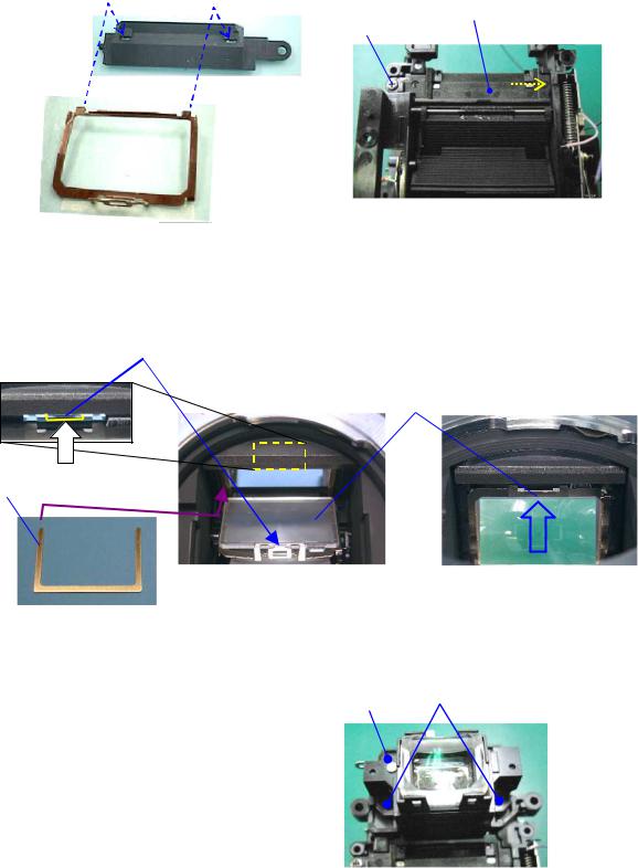
11. L2
[CAUTION] Confirm there is neither dust nor scratch on L2.
Install M21 to M4.
Install to front housing block with avoiding scratch on mirror. (M21 --- In first, put positioning post in the Front housing block.)
TY-CNL-D1.7x3.5
|
|
|
|
Unlock of M4.
M22 --- In the case of temporary adjustment, using with the M22-010E (0.35)
Put the focusing screen (L2) on the frame and then push it back until it locks in place.
12. M301
Eyepiece (M301, L7 and other) |
|
|
|
||
TY-CNL-D1.7x4.0 (x2) |
|
|
77420 - 27/107 -

13. [Adjustment] Viewfinder focus and parallax.
[Requires equipment] 50mm lens, collimator, focus master lens.
[Preparation]
1.Adjust the diopter by the diopter adjustment lever.
2.Set the AF mode switch to MF position. (Upper position)
13-1. Parallax
[CAUTION] Confirm that the pentaprism must be installed securely.
[Confirmation]Confirm there is neither gap nor an inclination at upper and lower, right and left position.
Standard: Right/Left Less than 0.5° Upside down Less than 0.5°
13-2. Viewfinder focus
[Confirmation] Confirm a viewfinder focus. *One scale for focus master lens is 0.03mm.
Standard: 0±0.07 mm
[Adjustment] Exchanges for M22 of other thickness.
The tolerance lever at the time of adjustment is 0±0.04 mm.
M22-00A |
-00B |
-00C |
-00D |
-00E |
-00F |
-00G |
-00H |
-00I |
-01J |
|
|
|
|
|
|
|
|
|
|
t=0.15 |
0.20 |
0.25 |
0.30 |
0.35 |
0.40 |
0.45 |
0.50 |
0.55 |
0.10 |
|
|
|
|
|
|
|
|
|
|
14. O100
Apply small amount of Daia bond (black) as shown in figure.M2 prism --- Make sure that there is no dust on M2.

O100, 27480-A640 |
|
|
|
TY-CNL-F1.7x3.0 |
|
|
|
|
|
|
|
TY-CNL-F1.7x4.5
--- Temporary tightens screws while holding O100 plate.
[Note of Disassembly]
1. |
Remove the screw lock which is stick to the screw. |
|
27480-A640 |
||
2. |
Unscrew (x2) while pressing the plate of 0-O100. |
|
|
|
|
|
|
|
|
||
|
|
|
|
||
3. |
If M2 does not replace, you do not necessary to |
|
|
|
|
|
|
|
|
||
|
disassembly. |
|
|
|
|
|
|
|
|
|
|
77420 - 28/107 -

15. [Adjustment] Positioning 0-O100 (Viewfinder indications)
[Preparation] O100 cable for 77170, O100 positioning jig for 76700, Power supply (8V,3A)
15-1. Preparation
Connect the O100 cable for 77170 to the jig as shown figure. |
|
|
Connect the flex board of O100 to the cable.↓ (Flip lock) |
|
|
Apply 6.0 V to the jig |
|
|
Turn the main switch ON. |
|
DC6V |
Turn the mode switch ON. |
|
|
|
|
|
*Indication of O100 is display. |
|
|
MODE
 MAIN
MAIN
15-2. Adjustment
[Confirmation] Check whether the position of the display is straight.
[Adjustment] Loosen the screw and change the position. |
|
|
|
After adjustment is done, apply screw lock. |
|
|
|
|
|
|
|
|
|
|
|
|
|
|
|
SL
16. 0-M100
[Preparation] Hexagonal screwdriver 1.5mm.
M100 [CAUTION] There is no dust and stain on the surface of lens.
TY-CNL-D1.7x4.0 (x3)
[Adjustment] Temporary adjustment of AF block.
--- Screw in 3 adjusting screws until they stops,
then screw back two turns.
[Note] After sensor position adjustment with programmed
Software is done, apply screw-lock agent to between the  head of adjustment screws and washers.
77420 - 29/107 -
 Loading...