


Service Manual
TOP NEXT
ORDER NO. MD0106137C2
DVD Home Theatre Sound System
• SA-HT70 Colour
(S)... Silver Type
Area
(E)... Continental Europe
(EB)... Great Britain
(EG)... Germany and Italy
MECHANISM :
RAE1805Z-S TRAVERSE UNIT
|
Specifications |
AMPLIFIER SECTION |
|
RMS TTL Power Output |
300 W |
(10% total harmonic distortion) |
|
Front (1 kHz) |
36 W per channel (6Ω ) |
Center (1 kHz) |
36 W (6Ω ) |
Surround (1 kHz) |
36 W per channel (6Ω ) |
Subwoofer (80 Hz) |
120 W (6Ω ) |
DIN TTL Power Output |
220 W |
(1.0% total harmonic distortion) |
|
Front (1 kHz) |
26 W per channel (6Ω ) |
Center (1 kHz) |
26 W (6Ω ) |
Surround (1 kHz) |
26 W per channel (6Ω ) |
Subwoofer (80 Hz) |
90 W (6Ω ) |
Input sensitivity/ input impedance |
|
AUX |
250 mV, 10 kΩ |
DISC SECTION |
|
Disc |
|
DVD |
8 cm/ 12 cm Single-Sided, SingleLayer |
|
8 cm/ 12 cm Single-Sided, Double-Layer |
|
8 cm/ 12 cm Double-Sided, DoubleLayer |
|
(One layer per side) |
CD/ VCD |
8 cm/ 12 cm (CD-R/ RW) |
Video |
|
Signal system |
NTSC/ PAL (depending on disc format) |
Output level |
Composite video 1 Vp-p (75Ω ) |
S-video Y |
1 Vp-p (75Ω ) |
S-video C |
0.300 Vp-p (75Ω / PAL) |
|
0.286 Vp-p (75Ω / NTSC) |
Audio |
|
Sampling frequency |
|
CD |
44.1 kHz |
DVD |
48 kHz/ 96 kHz |
Decoding |
16/ 20/ 24 bit linear |
Wow and flutter |
Below measurable limit |
D/ A converter |
Delta-sigma DAC |
Pick up |
|
Beam Source |
Semiconductor Laser |
Wavelength |
|
DVD |
658 nm |
http://servis-manual.com/

8 Self-Diagnostic Function
TOP PREVIOUS NEXT
Carry out the following procedure after repair works to ensure effee self diagnosis and tilt adjustment. When using the self diagnosis function, confirm that “NO DISC” is being displayed on the display panel and alsothe optical pickup has not been replaced yet. Carry out the self diagnosis in accordance to the guideline and replace the optical pickup when the current value of the laser drive is above 50.
[NOTE] Measure the value once the POWER button is depressed and power is connected before the equipment warm up (within 3 minutes).
•Carry out the following self diagnosis when “NO DISC” is being displayed on the display panel, the equipment does not read the disc or before the replacement of optical pickup.
1.When “NO DISC” is being displayed on the display panel, equipment does not function smoothly, etc.
2.Check the current value of the laser drive. With no disc in the drive, press the “Screen Display” button on the remote control while pressing the STOP button on the equipment.
3.Implement step 4 if the value is below 50. Replace the optical pickup when the value is above 50. After replacement, implement step 2 again and if the value of the optical pickup is above
40, replace the optical pickup again. There is a possiblityof electrostatic failure during replacement.
4.Carry out tilt adjustment of the optical pickup if the value of the optical pickup before replacement is below 50 or the value of the replaced optical pickup is below 40.
5.Carry out initial setting. Press the “> 10” button on the remote control while pressing the STOP button on the equipment. With this, the whole procedure is completed.
TOP PREVIOUS NEXT
http://servis-manual.com/

10.1 Mode List
TOP PREVIOUS NEXT
Use this function when performing maintenance on the unit.
Main unit |
Remote control |
Usage |
button |
button |
|
TUNE |
0 |
UHF display |
MODE |
5 |
Positioning adjustment |
|
||
|
6 |
Confirmation of area code, transmission method |
|
7 |
Confirmation of internal program version |
|
9 |
Total illumination of main unit display panel |
|
Screen Display |
Confirmation of laser drive current |
|
Pause |
Saving of laser drive current value after optical pickup replacement (Do not perform this operation other than for |
|
|
replacement of optical pickup) |
|
>10 |
Initialisation of main unit (Return to factory shipment settings) Carry out for replacement of micro computer, peripheral |
|
|
parts of micro computer or printed board. |
TOP PREVIOUS NEXT
http://servis-manual.com/

10.2 DVD Self Diagnostic Function - Error
Code
TOP PREVIOUS NEXT
Error |
Error Content |
Additional error explanation |
Defect 1 |
Defect 2 |
Defect 3 |
Defect 4 |
Code |
|
|
|
|
|
|
|
U, H error |
|
|
|
|
|
U11 |
Focus error |
|
|
|
|
|
H01 |
Tray loading error |
|
|
|
|
|
H02 |
Spindle servo error |
(Spindle servo, DSC SP motor, CLV servo |
|
|
|
|
|
|
error) |
|
|
|
|
H03 |
Traverse servo error |
|
|
|
|
|
H04 |
Tracking servo error |
|
|
|
|
|
H05 |
Seek error |
|
|
|
|
|
H06 |
Power error |
Cannot switch off the power because of the |
|
|
|
|
|
|
panel and system computer communication error |
|
|
|
|
|
DSC related |
|
|
|
|
|
F500 |
DSC error |
DSC stops in the occurence of servo error |
OPU |
ADSC |
FEP |
servo |
|
|
(starup, focus error, etc) |
|
|
|
drive |
F501 |
DSC not Ready |
DSC-system computer communication error |
ADSC |
CPU |
|
|
|
|
(Communication failure caused by idling of |
|
|
|
|
|
|
DSC) |
|
|
|
|
F502 |
DSC Time out error |
Similar disposal as F500 |
OPU |
ADSC |
FEP |
servo |
|
|
|
|
|
|
drive |
F503 |
DSC communication Failure |
Communication error (result error occured |
ADSC |
FEP |
EEPROM |
|
|
|
although communication command was sent) |
|
|
|
|
F505 |
DSC Attention error |
Similar disposal as F500 |
OPU |
ADSC |
FEP |
servo |
|
|
|
|
|
|
drive |
F506 |
Invalid media |
Disc is flipped over, TOC unreadable, |
DISC |
FEP |
ADSC |
ODC |
|
|
incompatible disc |
|
|
|
|
 ODC related
F600 Access failure to management information caused by demodulation error
Operation stopped because navigation data is not |
ODC |
FEP |
ADSC |
accessible caused by the demodulation defect |
|
|
|
F601 |
Indeterminate sector ID requested |
Operation stopped caused by the request to |
ODC |
FEP |
ADSC |
|
|
|
access abnormal ID data |
|
|
|
|
F602 |
Access failure to LEAD-IN caused by |
LEAD IN data unreadable |
|
|
|
|
|
demodulation error |
|
|
|
|
|
F603 |
Access failure to KEYDET caused by |
Access failure to CSS data of disc |
|
|
|
|
|
demodulation error |
|
|
|
|
|
F610 |
ODC abnormality |
No permission for command execution |
ODC |
|
|
|
F611 |
6626 QCODE don’t read Error |
Access failure to seek address in CD series |
ODC |
|
|
|
F612 |
No CRC OK for a specific time |
Access failure to ID data in DVD series |
ODC |
|
|
|
F630 |
No reply to KEY DET enquiry |
(for internal use only) |
|
|
|
|
F631 |
CPPM KEY DET is not available till |
(CPPM file system is unreadable caused by |
DISC |
CPPM |
|
|
|
the FILE terminal |
scratches) |
|
|
|
|
F632 |
CPPM KEY DET is not available |
Been revoked or falsified |
DISC |
EEPROM |
CPPM |
|
|
Disc code |
|
|
|
|
|
F103 |
Illegal highlight Position |
Big possibility of disc specification violation |
DISC |
|
|
|
|
|
during highlight display |
|
|
|
|
|
HIC Error |
|
|
|
|
|
F4FF |
Force initialize failure (time out) |
|
EEPROM |
CPU |
FEP |
ADSC |
|
Micro computer error |
|
|
|
|
|
F700 |
MBX overflow |
When replying message to disc manager |
|
|
|
|
F701 |
Message command does not end |
Next message is sent before replying to disc |
|
|
|
|
http://servis-manual.com/

F702 Message command changes
F880 Task number is not appropriate
F890 Sending message when message is being sent to AV task
 manager
Message is changed before it is sent as a reply to disc manager
message coming from a non-existing task Sending message to AV task
F891 |
Message couldn’t be sent to AV task |
Begin sending message to AV task |
|
F893 |
FROM falsification |
FROM |
CPU |
F894 |
EEPROM abnormality |
EEPROM |
Serial |
|
|
|
communication on |
|
|
|
lone |
F8A0 |
Message command is not appropriate |
Begin sending message to AV task |
|
TOP PREVIOUS NEXT
http://servis-manual.com/

10.3 Last Error Code saved during NO PLAY
TOP PREVIOUS NEXT
Error |
Error Content |
System computer |
Setting task |
System computer internal error |
code |
|
|
|
code |
F0BF |
6) Cannot playback because physical layer is not |
PCND_NOPLAY PHYSICAL |
DriveManager |
0xDOBF |
|
recoginizable |
0x50 |
|
|
F0C0 8) DVD: Cannot playback because it is not DVD |
PCND_NOPLAY VIDEO 0x70 |
DiscManager |
0xDOCO |
|
|
Video/Adio/VR |
|
|
|
F0C1 9) DVD: Prohibited by the restricted region code |
PCND_NOPLAY RCD 0x80 |
DiscManager |
0xDOC1 |
|
F0C2 A) DVD: PAL restricted playback |
PCND_NOPLAY PAL 0x90 |
DiscManager |
0xDOC2 |
|
F0C3 B) DVD: Parental lock setting prohibits the playback of the |
PCND_NOPLAY PTL 0xA0 |
DiscManager |
0xDOC3 |
|
|
entire title |
|
|
|
F0C4 C) VCD: Prohibited because it is in PHOTO CD format |
PCND_NOPLAY PHOTO CD |
DiscManager |
0xDOC4 |
|
|
|
0xB0 |
|
|
F0C5 VCD/CD: Prohibited bacause it is CDROM without CD-DA |
PCND_NOPLAY CDROM |
DiscManager |
0xDOC5 |
|
|
|
0xC0 |
|
|
TOP PREVIOUS NEXT
http://servis-manual.com/

10.4.1 Recovery after the DVD player is repaired
TOP PREVIOUS NEXT
When an FROM or an EEPROM in and on the module P.C.B. has replaced, carry out the recovery disc processing to optimize the drive.
Playback the disc above to process the recovery automatically.
Recovery disc (Product number: RFKZD5TR001 [SPC supply] )
FROM disc (Product number: RFKFRV45C040 [SPC supply] )
Note:
This unit requires no initialization process carried out after the traditional DVD players were repaired. When the recovery measures are taken, the customer setting will return to the factory setting as same as the procedure described in item of “Initialization” in10.1 is carried out. Write down the contents of the setting before recovery processing, and reset the player.
TOP PREVIOUS NEXT
http://servis-manual.com/

10.5 Retail shop lock function
TOP PREVIOUS NEXT
In order ro prevent damage to disc during display at retail shop, etc., this function disables “Retrieval of disc”.
“LOCKED” is displayed when the operation is selected and the operation would not function. There are 2 types of lock function on this equipment, i.e., Lock Mode A and Lock Mode B. 10.5.1 Setting Method
10.5.2 Removal method
TOP PREVIOUS NEXT
http://servis-manual.com/

10.5.1 Setting Method
TOP PREVIOUS NEXT
Lock Mode A
With the power turned to On, set the SELECTOR to “DVD/CD”. The lock function works by presing the “POWER” button on either the main unit or the remote control while continously pressing on the”TuneMODE” button on the main unit. (When the locked condition is working, “LOCKED” will appear on the display for 3 seconds before commencement of disc playback.)
Lock Mode B
With the power turned to ON, set the SELECTOR to DVD/CD. The lock function works by pressing the “POWER” button on either the main unit or the remote control while continously pressing on the “/MEMORY” buttonon the main unit. (When the locked condition is working, “LOCKED” will appear on the display for 3 seconds before commencement of disc playback.)
When in Lock Mode B, only the sound quality operating buttons will work while the rest of the buttons will not work.
TOP PREVIOUS NEXT
http://servis-manual.com/

10.5.2 Removal method
TOP PREVIOUS NEXT
Both Lock Mode A and B can be disabled by repeatling the setting methods. Furthermore, the lock functions can also be disabled by unplugging the power cord from the equipment. (“UNLOCKED” will appear on the display for 3 secondswhen the lock function is disabled.)
TOP PREVIOUS NEXT
http://servis-manual.com/
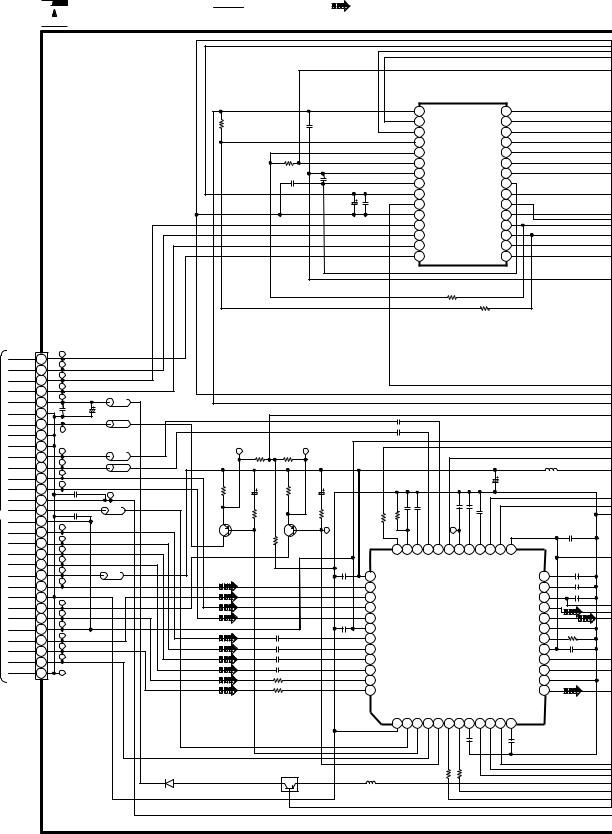
SCHEMATIC DIAGRAM - 1
: +B SIGNAL LINE |
: DVD (AUDIO/VIDEO) SIGNAL LINE |
 OPTICAL PICKUP UNIT
|
|
|
|
|
|
|
|
|
|
|
|
|
|
|
|
|
|
|
FOCUS |
TRACKING |
|
|
|
|
|
|
|
|
|
|
|
|
|
|
|
|
|
|
|
|
COIL |
COIL |
|
|
|
|
|
|
|
|
|
C002 |
|
|
|
|
|
|
|
|
|
|
|
|
|
|
|
|
|
|
|
|
|
|
22P |
|
|
|
|
|
|
|
|
|
|
|
|
|
|
|
|
|
|
|
|
C001 |
|
|
|
|
|
|
|
|
|
|
30 |
T+ |
|
|
|
|
|
|
|
|
|
|
|
|
|
|
|
|
|
|
|
29 |
F+ |
||
|
|
|
|
|
|
|
|
|
0.1 |
|
|
|
|
|
|
|
|
|
|
||
|
|
|
|
|
|
|
|
|
|
|
|
|
|
|
|
|
|
|
|
28 |
F- |
|
|
|
HFM |
|
|
|
|
|
C003 |
|
|
|
|
|
|
|
|
|
|
27 |
T- |
|
|
|
|
|
|
|
|
0.22 |
|
|
|
|
|
|
|
|
|
|
26 |
3.0V HFM |
|
|
|
|
|
|
|
|
|
|
-T |
|
|
|
|
|
|
|
|
|
|||
LDGND 1 |
|
|
|
|
6 LDGND |
|
|
|
|
|
|
|
|
|
|
|
25 |
GND |
|||
C4 L1 |
|
|
C2 |
|
|
BK1005H5601 |
|
|
|
|
|
|
|
|
|
||||||
LDIN |
2 |
R1 |
LC |
|
C3 |
5 |
LDOUT |
|
L001 |
|
|
|
|
|
|
|
|
|
24 |
LD+(DVD) |
|
|
MODULE |
|
|
|
|
|
|
|
|
|
|
|
|
|
23 |
GND |
|||||
3.0V |
|
C1 |
|
|
Q1 |
|
LDGND |
|
|
|
|
|
|
|
|
|
|
||||
3 |
R2 |
|
|
4 |
|
|
|
|
|
|
|
|
|
|
22 |
GND |
|||||
|
|
|
|
|
|
|
|
|
|
|
|
|
|
|
|||||||
|
|
|
|
|
|
|
|
|
|
|
|
|
|
|
|
|
|
|
|
21 |
RFP |
|
|
|
|
|
|
|
|
|
|
|
|
|
|
|
|
|
|
|
|
20 |
RFN |
|
|
|
|
|
|
|
|
|
|
|
|
|
|
|
|
|
|
|
|
19 |
F1(DVD) |
|
|
|
|
|
|
|
|
|
|
|
|
|
|
|
|
|
|
|
|
18 |
F2(DVD) |
|
|
|
|
|
|
|
|
|
|
C004 |
0.1 |
C005 |
0.1 |
R001 |
0 |
VR001 |
|
|
17 |
GAIN(H/L) |
|
|
|
|
|
|
|
|
|
|
|
|
|
|
PIN(DVD) |
||||||||
|
|
|
|
|
|
|
|
|
|
15K |
|
|
16 |
||||||||
|
|
|
|
|
|
|
|
|
|
|
|
|
|
|
|
|
|
|
|
15 |
VREF2.2V(DVD) |
|
|
|
|
|
|
|
|
|
|
|
|
|
|
|
|
|
|
|
|
14 |
TA(DVD) |
|
|
|
|
|
|
|
|
|
|
|
|
|
|
|
|
|
|
|
|
13 |
TD(DVD) |
|
|
|
|
|
|
|
|
|
|
|
|
|
|
|
|
|
|
|
|
12 |
TC(DVD) |
|
|
|
|
|
|
|
|
|
|
|
|
|
|
|
|
|
R004 |
|
|
11 |
TB(DVD) |
|
|
|
|
|
|
|
|
|
|
|
|
|
|
|
|
|
|
|
10 |
VCC5V |
|
|
|
|
|
|
|
|
|
|
|
|
|
|
|
|
|
|
|
|
|
||
|
|
|
|
|
|
|
|
|
|
|
|
|
|
|
|
0 |
0 |
|
|
FE1(CD) |
|
|
|
|
|
|
|
|
|
|
|
|
|
|
|
|
|
|
|
9 |
|||
|
|
|
|
|
|
|
|
|
|
|
|
|
|
|
|
|
|
|
|
8 |
GND |
|
|
|
|
|
|
|
|
|
GND |
|
|
LDGND |
|
|
|
|
|
7 |
LD+(CD) |
||
|
|
|
|
|
|
|
|
|
|
|
|
|
|
|
|
|
T1(CD) |
||||
|
|
|
VREF |
2 |
|
|
|
|
1 |
|
|
16 LD |
|
15 |
LD |
|
|
|
6 |
VREF2.2V(CD) |
|
|
|
|
VCC 3 |
|
|
x1 |
17K |
|
|
|
|
BIAS |
14 SW |
|
|
|
5 |
||||
|
|
|
T1 |
4 |
|
|
|
|
|
|
|
|
|
|
|
|
|
|
FE2(CD) |
||
|
|
|
|
|
|
|
Tr1 |
17K |
|
x1 |
|
|
13 F2 |
|
|
|
4 |
||||
|
|
|
|
|
|
|
|
|
|
|
|
|
|
|
|||||||
|
|
|
|
|
|
|
x2.75 |
|
|
|
|
|
|
|
|
T2(CD) |
|||||
|
|
|
|
|
|
|
|
|
|
|
|
|
|
|
|
|
|
|
3 |
||
|
|
|
T2 5 |
|
|
x1 |
17K |
Tr2 |
|
|
x2.75 |
|
|
|
|
|
|
|
PIN(CD) |
||
|
|
|
|
|
|
|
17K |
|
|
|
|
|
|
|
|
|
|||||
|
|
|
|
|
|
|
|
|
|
|
x1 |
|
|
12 F1 |
|
|
|
2 |
|
||
|
|
|
|
|
|
|
x2.75 |
|
|
|
|
|
|
|
|
|
|
GND |
|||
|
|
|
T3 |
6 |
|
|
x1 |
17K |
Tr3 |
|
|
x2.75 |
|
|
|
|
|
|
|
1 |
|
|
|
|
|
|
|
|
|
|
|
|
|
|
|
|
|
|
|
|
|
||
|
|
|
T4 7 |
|
|
x2.75 |
17K |
|
|
|
|
|
x1 |
11 RFN |
|
|
|
|
FP5201 |
||
|
|
|
|
|
x1 |
Tr4 |
|
|
|
|
x1 |
10 RFP |
|
|
|
|
|
||||
|
|
|
|
|
|
|
x2.75 |
|
|
|
|
|
|
|
|
|
|
|
|
||
|
|
|
|
|
|
|
|
|
|
|
|
|
|
|
|
|
|
|
|
|
|
|
|
|
MON |
|
|
|
|
|
|
|
|
|
Mon |
9 GND |
|
|
|
|
|
||
|
|
|
8 |
|
|
|
|
|
|
|
|
|
|
|
|
|
|
|
|||
|
|
|
|
|
|
|
|
|
|
|
|
|
|
|
|
|
|
|
|
|
|
|
|
|
|
|
|
|
|
|
DVDM |
|
|
|
|
|
|
|
|
|
|
|
|
|
|
|
|
|
|
|
|
|
|
|
|
|
|
|
|
|
|
|
C007 |
|
|
|
|
|
|
|
|
|
|
|
|
|
|
|
|
|
|
|
|
|
0.1 |
|
|
|
|
|
|
|
|
|
|
|
|
|
|
|
|
|
|
|
C008 |
|
R002 |
|
|
|
|
|
|
|
|
|
|
|
|
|
|
|
|
|
|
|
0.1 |
|
0 |
|
|
|
|
|
|
|
|
|
|
|
|
|
|
|
|
|
|
|
|
C009 |
VR002 |
|
|
|
|
|
|
|
|
|
|
|
|
|
|
|
|
|
|
|
|
1K |
|
|
|
|
|
|
|
|
|
|
|
|
|
|
|
|
|
|
|
|
|
0.1 |
|
|
|
|
|
|
|
|
|
|
|
|
|
|
|
|
|
|
|
|
|
|
|
|
|
|
|
|
|
|
|
MON 2 |
|
|
1 GND |
|
12LDGND |
|
|
|
|
|
|
|
|||
|
|
|
|
|
|
3 NC |
|
|
|
|
|
LD |
|
LD 11 |
|
|
|
|
|
||
|
|
|
|
|
|
|
Pmon |
|
|
|
|
|
|
|
|
|
|
||||
|
|
|
|
|
|
4 F1 |
|
P2 |
|
P3 |
|
|
|
|
F2 10 |
|
|
|
|
|
|
|
|
|
|
|
|
|
(60kΩ) |
P4 |
|
P7 |
|
(60kΩ) |
|
|
|
|
|
|
|
||
|
|
|
|
|
|
5 VREF |
|
P8 |
|
P9 |
|
|
|
VCC 9 |
|
|
|
|
|
||
|
|
|
|
|
|
(160kΩ) |
|
|
(160kΩ) |
|
|
|
|
|
|
||||||
|
|
|
|
|
|
|
|
|
P1 |
|
P5 |
|
|
|
|
F 8 |
|
|
|
|
|
|
|
|
|
|
|
6 E |
|
|
|
|
|
|
|
|
|
|
|
|
|
|
|
|
|
|
|
|
|
|
|
P6 |
|
P10 |
|
|
GND |
|
|
|
|
|
|||
|
|
|
|
|
|
|
|
|
|
|
|
|
|
|
|
7 |
|
|
|
|
|
|
|
|
|
|
|
|
|
|
CDM |
|
|
|
|
|
|
|
|
|
|
|
|
TO 

 DVD MODULE (1)CIRCUIT (FP5201) ON SCHEMATIC DIAGRAM-2
SCHEMATIC DIAGRAM - 2

 DVD MODULE(1) CIRCUIT
: +B SIGNAL LINE |
: DVD (AUDIO/VIDEO) SIGNAL LINE |
TO OPTICAL PICKUP UNIT (FP5201) ON  SCHEMATIC
  DIAGRAM-1
T+ 30
F+ 29
F- 28
T- 27 3.3VHFM 26
GND 25 LD+(DVD) 24
GND 23
GND 22
AFP 21
AFN 20 F1(DVD) 19
F2(DVD) 18 GAINH/L 17
PIN(DVD)VREF2.2 16
(DVD) 15 TA(DVD) 14 TD(DVD) 13 TC(DVD) 12 TB(DVD) 11
VCC5V 10 FE1 9 GND 8 LD+(CD) 7
T1(CD)
VREF2.2 6 (CD) 5
FE2(CD) 4
T2(CD) 3
PIN(CD) 2 GND 1
FP5201
|
|
|
|
|
|
|
|
|
|
|
|
|
|
|
|
|
|
|
|
|
|
IC2501 |
|
|
|
|
|
|
|
|
|
||
|
|
|
|
|
|
|
|
|
|
|
|
|
|
|
|
|
|
|
C0GBG0000020 |
|
|
|
|
|
|
||||||||
|
|
|
|
|
|
|
|
|
|
|
|
|
|
|
|
|
|
|
|
MOTOR DRIVE |
|
|
|
|
|
|
|
|
|||||
|
|
|
|
|
|
|
|
|
|
|
|
|
|
|
|
|
|
1 BIAS1 |
|
|
|
|
LDCNT 28 |
|
|
|
|
|
|||||
|
|
|
|
|
R2502 |
|
|
|
|
|
C2507 |
|
|
|
|
|
2 |
VIN1 |
|
|
|
|
MUTE3 27 |
|
|
|
|
|
|||||
|
|
|
|
|
15K |
|
|
|
|
|
|
|
|
|
|
|
|
|
|
|
|
|
|
|
|
|
|
|
|
|
|
||
|
|
|
|
|
|
|
|
|
|
0.1 |
|
|
|
|
|
3 |
VIN2 |
|
|
|
|
|
TRIN 26 |
|
|
|
|
|
|||||
|
|
|
|
|
|
|
|
|
|
|
|
|
|
|
|
|
|
|
|
|
|
|
|
|
|
||||||||
|
|
|
|
|
|
|
|
|
|
|
|
|
|
|
|
|
|
4 |
OPIN+ |
|
|
|
BIAS2 25 |
|
|
|
|
|
|||||
|
|
|
|
|
|
|
|
|
|
|
|
|
|
|
|
|
|
5 |
OPIN- |
IC2501 |
LDIN 24 |
|
|
|
|
|
|||||||
|
|
|
|
|
|
|
R2503 |
C2506 |
0.1 |
|
|
|
|
6 |
GND(PRE) |
|
|
|
VIN3 23 |
|
|
|
|
|
|||||||||
|
|
|
|
|
|
|
|
|
|
|
7 |
FIN |
|
|
|
|
PREVCC 22 |
|
|
|
|
|
|||||||||||
|
|
|
|
|
|
|
15K |
|
|
|
|
|
|
|
|
|
|
|
|
|
|
|
|
|
|
||||||||
|
|
|
|
|
|
C2508 |
0.1 |
|
|
|
|
|
|
|
|
|
FIN |
|
|
|
|
|
FIN |
|
|
|
|
|
|
||||
|
|
|
|
|
|
|
|
|
|
|
|
|
|
|
|
|
|
|
|
|
|
|
|
|
|
|
|
|
|
||||
|
|
|
|
|
|
|
|
|
|
|
|
|
|
C2504 |
|
|
8 |
VCC(CH1-2) |
|
VCC(CH3-4) 21 |
|
|
|
|
|
||||||||
|
|
|
|
|
|
|
|
|
|
|
|
|
C2501 |
|
|
9 |
MUTE12 |
|
|
|
MUTE4 20 |
|
|
|
|
|
|||||||
|
|
|
|
|
|
|
|
|
|
|
|
|
0.1 |
|
|
|
|
|
|
|
|
|
|
||||||||||
|
|
|
|
|
|
|
|
|
|
|
|
6.3V220P |
|
|
10 GND(CH1-2) |
|
GND(CH3-4) 19 |
|
|
|
|
|
|||||||||||
|
|
|
|
|
|
|
|
|
|
|
|
|
|
|
|
|
|
|
|
|
|
|
|
||||||||||
|
|
|
|
|
|
|
|
|
|
|
|
|
|
|
|
|
|
11 VO2- |
|
|
|
|
|
V0318 |
|
|
|
|
|
||||
|
|
|
|
|
|
|
|
|
|
|
|
|
|
|
|
|
|
12 VO2+ |
|
|
|
|
|
V03+ 17 |
|
|
|
|
|
||||
|
|
|
|
|
|
|
|
|
|
|
|
|
|
|
|
|
|
13 VO1- |
|
|
|
|
|
V0416 |
|
|
|
|
|
||||
|
|
|
|
|
|
|
|
|
|
|
|
|
|
|
|
|
|
14 VO1+ |
|
|
|
|
|
V04+ 15 |
|
|
|
|
|
||||
|
|
|
|
|
|
|
|
|
|
|
|
|
|
|
|
|
|
|
|
|
R2505 |
|
|
|
|
|
|
|
|
|
|
|
|
|
|
|
|
|
|
|
|
|
|
|
|
|
|
|
|
|
|
|
|
|
82K |
|
|
|
|
|
|
|
|
|
|
|
|
|
|
|
|
|
|
|
|
|
|
|
|
|
|
|
|
|
|
|
|
|
|
|
|
|
R2504 |
|
|
|
|
|
|
|
|
|
|
|
|
|
|
|
|
|
|
|
|
|
|
|
|
|
|
|
|
|
|
|
|
|
82K |
|
|
|
|
|
|
|
|
TC5225 |
|
|
|
|
|
|
|
|
|
|
|
|
|
|
|
|
|
|
|
|
|
|
|
|
|
|
|
|
|
|
|
|
|
TC5224 |
|
|
|
|
|
|
|
|
|
|
|
|
|
|
|
|
|
|
|
|
|
|
|
|
|
|
|
|
|
|
|
|
|
TC5223 |
|
|
|
|
|
|
|
|
|
|
|
|
|
|
|
|
|
|
|
|
|
|
|
|
|
|
|
|
|
|
|
|
|
TC5222 |
|
|
|
|
|
|
|
|
|
|
|
|
|
|
|
|
|
|
|
|
|
|
|
|
|
|
|
|
|
|
|
|
|
TC5221 |
|
LB5206 |
LB5205-LB5206 |
|
|
|
|
|
|
|
|
|
|
|
|
|
|
|
|
|
|
|
|
|
|
|
|
|
|
|
|
|
|
C5251 |
C5252 |
VLP0323A601R |
|
|
|
|
|
|
|
|
|
|
|
|
|
|
|
|
|
|
|
|
|
|
|
|
|
|
|
|
|
||
0.1 |
LB5203-LB5204 |
|
|
|
|
|
|
|
|
|
|
|
|
|
|
|
|
|
|
|
|
|
|
|
|
|
|
|
|
|
|||
10V10 |
|
|
|
|
|
|
|
|
|
|
|
|
|
|
|
|
|
|
|
|
|
|
|
|
|
|
|
|
|
||||
|
|
VLP0155-T |
|
|
|
|
|
|
|
|
|
|
C5225 |
0.1 |
|
|
|
|
|
|
|
|
|
|
|
|
|
|
|
|
|||
|
|
|
|
|
|
|
|
|
|
|
|
|
|
|
|
|
|
|
|
|
|
|
|
|
|
|
|
|
|
||||
TC5220 |
|
LB5205 |
|
|
|
|
|
|
|
|
|
|
|
C5224 |
0.1 |
|
|
|
|
|
|
|
|
|
|
|
|
|
|
|
|
||
TC5219 |
|
LB5204 |
|
TC5230R5217 |
R5213TC5229 |
|
|
|
|
|
|
|
|
|
|
|
|
|
|
|
|
|
|
|
|
|
|
||||||
TC5218 |
|
|
|
|
47K |
47K |
|
|
|
|
|
|
|
|
|
|
|
|
|
|
|
|
|
|
|
|
|
|
|
|
|
||
|
|
|
|
|
|
|
|
|
|
|
|
|
|
|
|
|
|
|
|
|
|
|
|
|
|
|
|
|
L5201 |
|
|||
|
|
|
|
|
|
|
|
|
|
|
|
|
|
|
|
|
|
|
|
|
|
|
|
|
|
|
|
|
|
|
|
||
TC5217 |
|
LB5203 |
|
|
|
|
|
|
|
|
|
|
|
|
|
|
|
|
|
|
|
|
|
|
|
C5201 |
ELJEA100KF |
|
|||||
TC5216 |
|
|
|
|
|
|
|
|
|
|
|
|
|
|
|
|
|
|
|
|
|
|
|
|
|
|
|
|
|
||||
|
|
R5212 |
|
C5211 6.3V47 |
|
R5216 |
|
C5215 |
6.3V47 |
|
|
|
|
|
|
|
|
|
|
|
|
|
|
|
16V10 |
|
|
|
|
||||
C5253 |
4700P |
TC5215 |
|
|
|
|
|
|
|
|
|
|
|
|
|
|
|
|
|
|
|
|
|
|
|
|
|
||||||
|
|
VLP0323A601R |
R5211 |
|
|
|
|
|
|
|
|
|
|
|
|
|
|
|
|
|
|
|
|
|
|
|
|
|
|||||
C5223 |
0.1 |
|
|
|
|
|
|
|
|
|
|
|
|
|
|
|
|
|
|
|
|
|
|
|
|
|
|
|
|||||
|
LB5202 |
2.2 |
|
|
|
|
|
|
|
|
|
|
|
|
|
|
|
|
|
|
|
|
|
|
|
|
|
||||||
|
|
|
|
|
|
|
|
|
|
|
|
|
|
|
|
|
|
|
|
|
|
|
|
|
|
|
|
||||||
TC5213 |
|
|
27 |
|
27 |
R5215 |
2.2 |
|
R5236 |
0 |
R52351M |
C5240560P |
C52390.1 |
|
|
TC5226 |
C52380.22 |
C52370.1 |
C52361000P |
|
|
|
|
|
|
|
|
||||||
|
|
|
|
|
|
|
|
|
|
|
|
|
|
|
|
||||||||||||||||||
TC5212 |
|
|
|
Q5211 R521422K |
|
Q5215 |
TC5227 |
|
|
|
|
|
|
|
|
|
|
|
|
|
|
|
|
|
|
|
C5204 |
||||||
TC5211 |
|
|
|
|
|
|
|
|
|
|
|
|
|
36 |
35 |
34 |
33 |
32 |
31 |
30 |
29 |
28 |
27 |
26 |
25 |
|
|
|
0.1 |
|
|||
TC5210 |
|
|
|
|
|
|
|
|
|
|
C5203 |
37 VCC1 RFENV |
PEAK |
OCRF |
RFINN |
RFINP |
TESTSG |
AGC6 |
|
DCAGC |
SAG |
FLTON |
FLTOP |
VCC2 |
|
|
|
|
|
||||
TC5209 |
|
LB5201 |
|
|
|
|
|
|
|
|
|
|
|
|
|
|
|||||||||||||||||
|
|
|
|
|
|
|
|
|
0.1 |
|
|
BDDSL 24 |
C5235 |
390P |
|||||||||||||||||||
TC5208 |
JALBK2HS470T |
|
|
|
|
|
|
|
|
|
|
|
C5234 2200P |
||||||||||||||||||||
|
|
|
|
|
|
|
|
|
|
38 VIN5 |
|
|
|
|
|
|
|
|
|
|
|
|
|
|
OFTSL 23 |
||||||||
|
|
|
|
|
|
|
|
|
|
|
|
|
|
|
|
|
|
|
|
|
|
|
|
|
|
|
|
|
|
||||
|
|
|
|
|
|
|
|
|
|
|
|
|
|
39 VIN6 |
|
|
|
|
|
|
|
|
|
|
|
|
|
|
VHALF |
22 |
C5233 |
0.1 |
|
TC5207 |
|
|
|
|
|
|
|
|
|
|
|
|
|
|
|
|
|
|
|
|
|
|
|
|
|
|
|
|
|||||
|
|
|
|
|
|
|
|
|
|
|
|
40 VIN7 |
|
|
|
|
|
|
|
|
|
|
|
|
|
|
FB 21 |
|
|
||||
TC5206 |
|
|
|
|
|
|
|
|
|
|
|
|
|
|
|
|
|
|
|
|
|
|
|
|
|
|
|
|
|||||
|
|
|
|
|
|
|
|
|
|
|
|
41 VIN8 |
|
|
|
|
|
|
|
|
|
|
|
|
|
|
FE 20 |
|
|
||||
TC5205 |
|
|
|
|
|
|
|
|
|
|
|
C5221 |
|
|
|
|
|
IC5201 |
|
|
|
|
|
|
|||||||||
|
|
|
|
|
|
|
|
|
|
|
42 VREF2 |
|
|
|
|
|
|
|
|
GND2 19 |
|
|
|||||||||||
|
|
|
|
|
|
|
|
|
|
|
|
|
|
|
|
|
|
|
|
R5232 |
|||||||||||||
TC5204 |
|
|
|
|
C5205 |
1000P |
|
|
|
0.1 |
43 VIN1 |
|
|
|
|
AN8708FHK |
|
|
|
|
RSCL |
18 |
|||||||||||
|
|
|
|
|
|
|
|
|
|
|
|
|
|
|
12K |
|
|||||||||||||||||
TC5203 |
|
|
|
|
C5206 |
1000P |
|
|
|
|
44 |
VIN2 |
|
|
|
|
|
|
FEP |
|
|
|
|
|
|
VDD 17 |
|
||||||
|
|
|
|
|
|
|
|
|
|
|
|
|
|
|
|
|
|
|
|
|
|
|
|
||||||||||
|
|
|
|
|
|
C5207 |
1000P |
|
|
|
|
|
|
|
|
|
|
|
|
|
|
|
|
|
|
C5232 |
|||||||
TC5202 |
|
|
|
|
|
|
|
|
45 |
VIN3 |
|
|
|
|
|
|
|
|
|
|
|
|
|
|
BDD |
16 |
|||||||
|
|
|
|
|
|
C5208 |
1000P |
|
|
|
|
|
|
|
|
|
|
|
|
|
|
|
|
|
|
0.1 |
|
||||||
|
|
|
|
|
|
|
|
|
|
|
VIN4 |
|
|
|
|
|
|
|
|
|
|
|
|
|
|
OFTR 15 |
|
||||||
TC5201 |
|
|
|
|
|
|
|
|
46 |
|
|
|
|
|
|
|
|
|
|
|
|
|
|
|
|
||||||||
|
|
|
|
R5221 |
8.2K |
|
|
|
|
|
|
|
|
|
|
|
|
|
|
|
|
|
|
|
|
|
|||||||
|
|
|
|
|
|
|
|
|
47 |
VIN9 |
|
|
|
|
|
|
|
|
|
|
|
|
|
|
VSS 14 |
|
|
||||||
|
|
|
|
|
|
|
|
|
|
|
|
|
|
|
|
|
|
|
|
|
|
|
|
|
|
|
|||||||
|
|
|
|
|
|
R5222 |
8.2K |
|
|
|
|
|
|
|
|
|
|
|
|
|
|
|
|
|
|
|
|
|
|||||
|
|
|
|
|
|
|
|
|
|
|
48 VIN10 |
|
|
|
|
|
|
|
|
|
|
|
|
|
TE 13 |
|
|
||||||
|
|
|
|
|
|
|
|
|
|
|
|
|
|
|
|
|
|
|
|
|
|
|
|
|
|
|
|
|
|||||
|
|
|
|
Q5211 |
|
Q5215 |
|
|
|
|
|
|
|
GND1 |
LPC1 |
LPCD1 |
LPC2 |
LPCD2 |
FBAL |
TBAL |
|
PDFLT |
|
|
STDIO |
VREF1 |
|
|
|
|
|
||
|
|
|
|
2SB1115-T |
2SB1115-T |
|
|
|
|
|
|
SEN |
SCK |
|
|
|
|
|
|||||||||||||||
|
|
|
|
LD SUPPLY SWITCH |
CD SUPPLY SWITCH |
|
|
|
|
|
|
|
|
|
|
||||||||||||||||||
|
|
|
|
|
|
|
|
1 |
2 |
3 |
4 |
5 |
6 |
7 |
|
8 |
9 |
10 |
11 |
12 |
|
|
|
|
|
||||||||
|
|
|
|
QR5215 |
|
|
|
|
|
|
|
|
|
|
|
|
|
|
|
|
|||||||||||||
|
|
|
|
UN2121-TX |
|
|
|
|
|
|
|
|
|
|
|
|
|
|
|
|
|
C5231 |
100P |
|
|
|
C5242 |
|
|
|
|||
|
|
|
|
SUPPLY SWITCH (+3.3V) |
|
|
|
|
|
|
|
|
|
|
|
|
|
|
|
|
|
|
|
|
|
|
|
||||||
|
|
|
|
|
|
|
|
|
|
|
|
|
|
|
|
|
|
|
|
|
|
|
|
|
|
4700P |
|
|
|
||||
|
|
|
|
|
|
QR5251 |
|
|
|
|
L5251 |
|
|
|
R5203 |
|
R5204 |
|
|
|
|
|
|
|
|
||||||||
|
|
|
|
|
|
|
|
|
|
|
|
|
|
|
|
|
|
56K |
|
|
|
22K |
|
|
|
|
|
|
|
|
|||
|
|
|
|
D5251 |
|
|
|
|
|
|
|
|
|
ELJEA100KF |
|
|
|
|
|
|
|
|
|
|
|
|
|
|
|
|
|
|
|
|
|
|
|
|
|
|
|
|
|
|
|
|
|
|
|
|
|
|
|
|
|
|
|
|
|
|
|
|
|
|
|
|
|
|
|
|
|
MA728TX |
|
|
|
|
|
|
|
|
|
|
|
|
|
|
|
|
|
|
|
|
|
|
|
|
|
|
|
|
|
 Loading...