


PMX1207007CE
CD Stereo System
Model No. SA-AKX74LM-K
Product Color: (K)...Black Type
Please refer to the original service manual for:
 CD Mechanism Unit (BRS11C), Order No. PSG1201019AE
 Speaker system SB-AKX74LM-K, Order No. PMX1207006CE
© Panasonic Corporation 2012. All rights reserved. Unauthorized copying and distribution is a violation of law.

Please refer to the original service manual for:
 CD Mechanism Unit (BRS11C), Order No. PSG1201019AE
 Speaker system SB-AKX74LM-K, Order No. PMX1207006CE
Nota: El idioma original de este Manual de Servicio es en idioma inglés, sin embargo algunas notas aquí mencionadas serán escritas en español para mejor descripción para Centros de Servicio de México.
TABLE OF CONTENTS
1 Safety Precautions |
4 |
Specifications |
1.1. General Guidelines |
5 |
General/Introduction |
1.3. Before Repair and Adjustment |
|
5.1. Media Information |
1.4. Protection Circuitry |
6 |
Location of Controls and Components |
1.5. Caution For Fuse Replacement |
|
6.1. Remote Control Key Button Operation |
1.6. Safety Parts Information |
|
6.2. Main Unit Key Button Operation |
2 Warning |
7 |
Installation Instructions |
2.1. Prevention of Electrostatic Discharge (ESD) |
|
7.1. Speaker and A/C Connection |
to Electrostatic Sensitive (ES) Devices |
8 |
Service Mode |
2.2. Precaution of Laser Diode |
|
8.1. Cold-Start |
2.3. Service caution based on Legal restrictions |
|
8.2. Doctor Mode Table |
2.4. Handling Precautions for Traverse Unit |
|
8.3. Reliability Test Mode (CD Mechanism Unit |
3 Service Navigation |
|
(BRS11C)) |
3.1. Service Information |
|
8.4. Self-Diagnostic Mode |
|
|
8.5. Self-Diagnostic Error Code Table |
2
8.6. Sales Demonstration Lock Function |
|
|
16 Schematic Diagram |
||||
9 Troubleshooting Guide |
|
|
|
|
|
16.1. Schematic Diagram Notes |
|
9.1. Part Location |
|
|
|
|
|
|
16.2. CD Servo Circuit |
9.2. Troubleshooting Guide for F61 and/or F76 |
|
16.3. Main(MICON) Circuit |
|||||
9.3. D-Amp IC Operation & Control |
|
|
|
16.4. Main(D-Amp) Circuit |
|||
10 Service Fixture & Tools |
|
|
|
|
|
16.5. Panel Circuit |
|
11 Disassembly and Assembly Instructions |
|
16.6. Remote Sensor, USB, Music Port , Memory |
|||||
11.1. Disassembly Flow Chart |
|
|
|
|
LED, Top Bar LED and Bottom Bar LED |
||
11.2. Main Components and P.C.B. Locations |
|
Circuit |
|||||
11.3. Disassembly of Top Cabinet |
|
|
|
|
16.7. CD Interface, Mic and Voltage Selector Circuit |
||
11.4. Disassembly of Front Panel Unit |
|
|
16.8. D-Amp Circuit |
||||
11.5. Disassembly of Mic P.C.B. |
|
|
|
|
16.9. SMPS Circuit |
||
11.6. Disassembly of Panel P.C.B. |
|
|
|
17 Printed Circuit Board |
|||
11.7. Disassembly of Memory LED P.C.B. |
|
|
17.1. CD Servo P.C.B. |
||||
11.8. Disassembly of Remote Sensor P.C.B. |
|
17.2. Main P.C.B. (Side A) |
|||||
11.9. Disassembly of USB P.C.B. |
|
|
|
|
17.3. Main P.C.B. (Side B) |
||
11.10. Disassembly of Music Port P.C.B. |
|
|
17.4. Panel, Remote Sensor, USB and Music Port |
||||
11.11. Disassembly of Top Bar LED P.C.B. |
|
|
P.C.B. |
||||
11.12. Disassembly of Bottom Bar LED P.C.B. |
|
17.5. Memory LED, CD Interface, Top Bar LED, |
|||||
11.13. Disassembly of Main P.C.B. |
|
|
|
|
Bottom Bar LED and Mic P.C.B. |
||
11.14. Replacement |
of |
Voltage |
Regulator |
IC |
17.7. SMPS and D-Amp P.C.B. |
||
(IC2010) |
|
|
|
|
|
|
18 Appendix Information of Schematic Diagram |
11.15. Replacement |
of |
Voltage |
Regulator |
IC |
18.1. Voltage & Waveform Chart |
||
(IC2011) |
|
|
|
|
|
|
18.2. Illustration of ICs, Transistor and Diode |
11.16. Replacement |
of |
Audio |
Digital |
Amp |
IC |
18.3. Terminal Function of ICs |
|
(IC5800) |
|
|
|
|
|
|
19 Exploded View and Replacement Parts List |
11.17. Replacement |
of |
Audio |
Digital |
Amp |
IC |
19.1. Exploded View and Mechanical replacement |
|
(IC5700) |
|
|
|
|
|
|
Part List |
11.18. Disassembly of D-Amp P.C.B. |
|
|
|
19.2. Electrical Replacement Part List |
|||
11.19.Replacement of Audio Digital Amp IC (IC5900)
11.20.Disassembly of SMPS P.C.B.
11.21.Replacement of Switching Regulator IC (IC5701)
11.22.Replacement of Rectifier Diode (D5702)
11.23.Replacement of Rectifier Diode (D5801)
11.24.Replacement of Rectifier Diode (D5802)
11.25.Replacement of Regulator Diode (D5803)
11.26.Disassembly of CD Mechanism Unit (BRS11C)
11.27.Disassembly of CD Interface P.C.B.
11.28.Disassembly of CD Servo P.C.B.
11.29.Disassembly of Rear Panel
12 Service Position
12.1.Checking and Repairing of Main P.C.B.
12.2.Checking and Repairing of D-Amp P.C.B.
12.3.Checking and Repairing of Panel P.C.B.
12.4.Checking and Repairing of SMPS P.C.B. -
12.5.Checking and Repairing of CD Servo P.C.B. (Side A)
12.6.Checking and Repairing of CD Servo P.C.B.
(Side B)
13 Simplified Block Diagram
13.1. Power Block Diagram
14 Block Diagram
14.1.Servo & System Control
14.2.IC Terminal Chart
14.3.Audio
14.4.Power Supply
15 Wiring Connection Diagram
3

1 Safety Precautions
1.1.General Guidelines
1.When servicing, observe the original lead dress. If a short circuit is found, replace all parts which have been overheated or damaged by the short circuit.
2.After servicing, see to it that all the protective devices such as insulation barriers, insulation papers shields are properly installed.
3.After servicing, carry out the following leakage current checks to prevent the customer from being exposed to shock hazards.
1.1.1.Leakage Current Cold Check
1.Unplug the AC cord and connect a jumper between the two prongs on the plug.
2.Measure the resistance value, with an ohmmeter, between the jumpered AC plug and each exposed metallic cabinet part on the equipment such as screwheads, connectors, control shafts, etc. When the exposed metallic part has a return path to the chassis, the reading should be between 1M: and 5.2M:.
When the exposed metal does not have a return path to the chassis, the reading must be 
1.1.2.Leakage Current Hot Check
1.Plug the AC cord directly into the AC outlet. Do not use an isolation transformer for this check.
2.Connect a 1.5k:, 10 watts resistor, in parallel with a 0.15ΠF capacitors, between each exposed metallic part on the set and a good earth ground such as a water pipe, as shown in Figure 1.
3.Use an AC voltmeter, with 1000 ohms/volt or more sensitivity, to measure the potential across the resistor.
4.Check each exposed metallic part, and measure the voltage at each point.
5.Reverse the AC plug in the AC outlet and repeat each of the above measurements.
6.The potential at any point should not exceed 0.75 volts RMS. A leakage current tester (Simpson Model 229 or equivalent) may be used to make the hot checks, leakage current must not exceed 1/2 milliamp. In case a measurement is outside of the limits specified, there is a possibility of a shock hazard, and the equipment should be repaired and rechecked before it is returned to the customer.
Figure 1
4

1.3.Before Repair and Adjustment
Disconnect AC power to discharge unit AC Capacitors as such (C5700, C5701, C5703, C5708) through a 10 Ω, 10 W resistor to ground.
Caution:
DO NOT SHORT-CIRCUIT DIRECTLY (with a screwdriver blade, for instance), as this may destroy solid state devices. After repairs are completed, restore power gradually using a variac, to avoid overcurrent.
Current consumption at AC 127 V, 60 Hz in Power ON, FM Tuner, No Signal, volume minimal mode should be ~ 750 mA.
1.4.Protection Circuitry
The protection circuitry may have operated if either of the following conditions are noticed:
No sound is heard when the power is turned on.
Sound stops during a performance.
The function of this circuitry is to prevent circuitry damage if, for example, the positive and negative speaker connection wires are “shorted”, or if speaker systems with an impedance less than the indicated rated impedance of the amplifier are used.
If this occurs, follow the procedure outlines below:
1.Turn off the power.
2.Determine the cause of the problem and correct it.
3.Turn on the power once again after one minute.
Note:
When the protection circuitry functions, the unit will not operate unless the power is first turned off and then on again.
1.5.Caution For Fuse Replacement
5
1.6.Safety Parts Information
Safety Parts List:
There are special components used in this equipment which are important for safety.
These parts are marked by  in the Schematic Diagrams, Exploded View & Replacement Parts List. It is essential that these critical parts should be replaced with manufacturer’s specified parts to prevent shock, fire or other hazards. Do not modify the original design without permission of manufacturer.
|
Modelo: |
SC-AKX74LM-K |
|
|
|
|
|
|
|
Safety |
Nombre del componente |
|
Número de Parte |
|
|
|
|
|
|
|
CABLE TOMACORRIENTE. |
K2CB2YY00059 |
||
|
|
|
||
|
CONECTOR TOMACORRIENTE |
K2AB2B000007 |
||
|
|
|
||
|
TRANSFORMADOR DE PODER |
G4DYZ0000060 |
||
|
|
|
||
|
TRANSFORMADOR DE |
ETS19AB2E6AG |
||
|
|
RESPALDO |
||
|
|
|
||
|
|
|
||
|
FUSIBLE PRIMARIO |
K5D802APA008 |
||
|
|
|
|
|
|
|
ZNR |
ERZV05Z471CS |
|
|
|
|
||
|
CAPACITOR DE AC |
F1BAF1020020 |
||
|
|
|
||
|
CAPACITOR DE AC |
F0CAF224A105 |
||
|
|
|
||
|
CAPACITOR DE AC |
F0CAF104A105 |
||
|
|
|
||
|
CAPACITOR DE AC |
F1BAF471A013 |
||
|
|
|
||
|
OPTOACOPLADOR |
B3PBA0000579 |
||
|
|
|
|
|
|
|
PCB SMPS |
RJB3568A |
|
|
|
RJB3568A-1 |
||
|
|
|
|
|
|
|
|
||
|
BOBINA PRIMARIO |
G0B932H00002 |
||
|
|
|
||
|
GAB. MET. SIN DOBLAR |
RKMX1011Z-KL |
||
|
BRS1C CD UNIT |
RD-DDL100-PX |
||
|
|
REAR PANEL |
RXTM0002H-A |
|
|
|
INSTRUCTIVO |
RQTM0189 |
|
|
|
RQTM0189-1 |
||
|
|
|
|
|
|
OPTOACOPLADOR |
B3PBA0000503 |
||
|
|
|||
|
Nota: El Optoacoplador B3PBA0000503 |
|||
|
cambiara por el B3PBA0000597 con la TI |
|||
|
A12031 Running Change |
|
||
 La pista de SMPS Cambiara Con la TI
A12037 de RJB3568A a RJB3568A -1 (
Running Change )
6
2 Warning
2.1.Prevention of Electrostatic Discharge (ESD) to Electrostatic Sensitive
(ES) Devices
Some semiconductor (solid state) devices can be damaged easily by static electricity. Such components commonly are called Electrostatically Sensitive (ES) Devices. Examples of typical ES devices are integrated circuits and some field-effect transistors and semiconductor "chip" components. The following techniques should be used to help reduce the incidence of component damage caused by electrostatic discharge (ESD).
1.Immediately before handling any semiconductor component or semiconductor-equipped assembly, drain off any ESD on your body by touching a known earth ground. Alternatively, obtain and wear a commercially available discharging ESD wrist strap, which should be removed for potential shock reasons prior to applying power to the unit under test.
2.After removing an electrical assembly equipped with ES devices, place the assembly on a conductive surface such as aluminum foil, to prevent electrostatic charge buildup or exposure of the assembly.
3.Use only a grounded-tip soldering iron to solder or unsolder ES devices.
4.Use only an anti-static solder removal device. Some solder removal devices not classified as “anti-static (ESD protected)” can generate electrical charge sufficient to damage ES devices.
5.Do not use freon-propelled chemicals. These can generate electrical charges sufficient to damage ES devices.
6.Do not remove a replacement ES device from its protective package until immediately before you are ready to install it. (Most replacement ES devices are packaged with leads electrically shorted together by conductive foam, aluminum foil or comparable conductive material).
7.Immediately before removing the protective material from the leads of a replacement ES device, touch the protective material to the chassis or circuit assembly into which the device will be installed.
Caution:
Be sure no power is applied to the chassis or circuit, and observe all other safety precautions.
8.Minimize bodily motions when handling unpackaged replacement ES devices. (Otherwise harmless motion such as the brushing together of your clothes fabric or the lifting of your foot from a carpeted floor can generate static electricity (ESD) sufficient to damage an ES device).
7

2.2.Precaution of Laser Diode
Caution:
This product utilizes a laser diode with the unit turned “on”, invisible laser radiation is emitted from the pickup lens. Wavelength: 790 nm (CD)
Maximum output radiation power from pickup: 100 ΠW/VDE
Laser radiation from the pickup unit is safety level, but be sure the followings:
1.Do not disassemble the pickup unit, since radiation from exposed laser diode is dangerous.
2.Do not adjust the variable resistor on the pickup unit. It was already adjusted.
3.Do not look at the focus lens using optical instruments.
4.Recommend not to look at pickup lens for a long time.
8

2.3.Service caution based on Legal restrictions
2.3.1.General description about Lead Free Solder (PbF)
The lead free solder has been used in the mounting process of all electrical components on the printed circuit boards used for this equipment in considering the globally environmental conservation.
The normal solder is the alloy of tin (Sn) and lead (Pb). On the other hand, the lead free solder is the alloy mainly consists of tin (Sn), silver (Ag) and Copper (Cu), and the melting point of the lead free solder is higher approx.30 degrees C (86θF) more than that of the normal solder.
Definition of PCB Lead Free Solder being used
The letter of “PbF” is printed either foil side or components side on the PCB using the lead free solder.
(See right figure)
Service caution for repair work using Lead Free Solder (PbF)
•The lead free solder has to be used when repairing the equipment for which the lead free solder is used. (Definition: The letter of “PbF” is printed on the PCB using the lead free solder.)
•To put lead free solder, it should be well molten and mixed with the original lead free solder.
•Remove the remaining lead free solder on the PCB cleanly for soldering of the new IC.
•Since the melting point of the lead free solder is higher than that of the normal lead solder, it takes the longer time to melt the lead free solder.
•Use the soldering iron (more than 70W) equipped with the temperature control after setting the temperature at 350±30 degrees
C (662±86θF).
Recommended Lead Free Solder (Service Parts Route.)
•The following 3 types of lead free solder are available through the service parts route. RFKZ03D01K-----------(0.3mm 100g Reel)
RFKZ06D01K-----------(0.6mm 100g Reel) RFKZ10D01K-----------(1.0mm 100g Reel)
Note
* Ingredient: tin (Sn), 96.5%, silver (Ag) 3.0%, Copper (Cu) 0.5%, Cobalt (Co) / Germanium (Ge) 0.1 to 0.3%
9

2.4.Handling Precautions for Traverse Unit
The laser diode in the optical pickup unit may break down due to static electricity of clothes or human body. Special care must be taken avoid caution to electrostatic breakdown when servicing and handling the laser diode in the traverse unit.
2.4.1.Cautions to Be Taken in Handling the Optical Pickup Unit
The laser diode in the optical pickup unit may be damaged due to electrostatic discharge generating from clothes or human body. Special care must be taken avoid caution to electrostatic discharge damage when servicing the laser diode.
1.Do not give a considerable shock to the optical pickup unit as it has an extremely high-precise structure.
2.To prevent the laser diode from the electrostatic discharge damage, the flexible cable of the optical pickup unit removed should be short-circuited with a short pin or a clip.
3.The flexible cable may be cut off if an excessive force is applied to it. Use caution when handling the flexible cable.
4.The antistatic FPC is connected to the new optical pickup unit. After replacing the optical pickup unit and connecting the flexible cable, cut off the antistatic FPC.
10
2.4.2.Grounding for electrostatic breakdown prevention
Some devices such as the DVD player use the optical pickup (laser diode) and the optical pickup will be damaged by static electricity in the working environment. Proceed servicing works under the working environment where grounding works is completed.
2.4.2.1.Worktable grounding
1. Put a conductive material (sheet) or iron sheet on the area where the optical pickup is placed, and ground the sheet.
2.4.2.2.Human body grounding
1. Use the anti-static wrist strap to discharge the static electricity form your body.
11
3 Service Navigation
3.1.Service Information
This service manual contains technical information which will allow service personnel’s to understand and service this model. Please place orders using the parts list and not the drawing reference numbers.
If the circuit is changed or modified, this information will be followed by supplement service manual to be filed with original service manual.
•CD Mechanism Unit (BRS11C):
1)This model uses CD Mechanism Unit (BRS11C).
•Micro-processor:
1)The following components are supplied as an assembled part.
- Micro-processor IC, IC2003 (MN101EF16KXW) Este material se encuentra sin programar, debe ser programado.
•Speaker System:
1) This model uses Speaker System, SB-AKX54, SB-WAKX74LM-K.
12

4 Specifications
Sección del amplificador
AKX74
Potencia de salida RMS en modo estéreo
Canal frontal alto (ambos canales controlados)
145 W por canal (5 Ω), 1 kHz, 10% THD 190 W por canal (5 Ω), 1 kHz, 30% THD
Canal frontal bajo (ambos canales controlados)
180 W por canal (4 Ω), 1 kHz, 10% THD 235 W por canal (4 Ω), 1 kHz, 30% THD
Subwoofer Ch
250 W por canal (8 Ω), 100 Hz, 10% THD 300 W por canal (8 Ω), 100 Hz, 30% THD
Potencia total RMS del modo estéreo
|
900 W (10% THD) |
|
1150 W (30% THD) |
Potencia de salida PMPO |
12700 W |
Sección del sintonizador, terminales
Emisoras preconfiguradas |
30 emisoras de FM |
|
15 emisoras de AM |
Modulación de frecuencia (FM) |
|
Gama de frecuencias |
|
87,5 MHz a 108,0 MHz (en pasos de 100 kHz) 87,9 MHz a 107,9 MHz (en pasos de 200 kHz)
Terminales de la antena 75 Ω (desbalanceado)
Modulación de amplitud (AM)
Gama de frecuencias
520 kHz a 1710 kHz (en pasos de 10 kHz)
Toma de micrófono |
0,7 mV, 1,1 kΩ |
Sensibilidad |
|
Terminal |
Mono, toma de 3,5 mm |
|
(1 sistema) |
Puerto de música (frontal) |
100 mV, 4,7 kΩ |
Sensibilidad |
|
Terminal |
Estéreo, toma de 3.5 mm |
Entrada AUX |
Clavija jack RCA |
Sección de discos compactos
Discos reproducidos (8 cm o 12 cm)
|
|
|
|
CD, CD-R/RW (CD-DA, MP3Ú) |
Lector |
|
|||
Longitud de onda |
790 nm (CD) |
|||
Potencia de láser |
CLASS 1 (CD) |
|||
Salida de audio (Disco) |
|
|||
Número de canales |
|
|||
|
|
|
|
2,1 canales (FL, FR, SW) |
|
AKX74 |
|
||
|
|
2 canales (FL, FR) |
||
|
|
|
||
|
AKX54 |
|||
FL = Canal frontal izquierdo FR = Canal frontal derecho SW = Canal de subwoofer Ú MPEG-1 Layer 3
Sección de memoria
Memoria |
|
Tamaño de la memoria |
2 GB |
Compatibilidad con formato de archivos de medios |
|
|
MP3 (*.mp3) |
Cómo grabar en la memoria |
|
Velocidad de bits |
128 kbps |
Velocidad de grabación en la memoria |
|
|
1x, 3x (CD solamente) |
Formato de archivo de grabación |
MP3 (*.mp3) |
Capacidad de total de canciones |
510 canciones |
grabadas (Usa 128 kbps, |
|
aproximadamente 1 canción = |
|
4 minutos) |
|
Sección de USB
Puerto USB |
|
Estándar USB |
USB 2,0 velocidad total |
Compatibilidad con formato de archivos de medios |
|
|
MP3 (*.mp3) |
Sistema de archivo de dispositivo USB |
|
|
FAT12, FAT16, FAT32 |
Energía puerto USB |
500 mA (máx.) |
Velocidad de bits |
16 kbps a 320 kbps |
|
(reproducción) |
Cómo grabar en el USB |
|
Velocidad de bits |
128 kbps |
Velocidad de grabación USB |
1x, 3x (CD solamente) |
Formato de archivo de grabación |
MP3 (*.mp3) |
Generalidades
Fuente de alimentación |
~127 V, 60 Hz |
Consumo de energía |
132 W |
|
Dimensiones (An x Al x Prf) 220 mm x 334 mm x 245 mm |
|
Peso |
3,4 kg |
|
|
Gama de temperaturas de funcionamiento |
|
|
0°C a +40°C |
Gama de humedades de funcionamiento |
|
|
35% a 80% humedad relativa |
|
(sin condensación) |
|
|
Consumo de energía en modo normal
132Wh/día (considerando 1 hora de uso al día).
Consumo de energía en modo de espera
4,6Wh/día (considerando 23 horas en modo de espera al día).
Nota:
Las especificaciones están sujetas a cambios sin previo aviso.
El peso y las dimensiones son aproximados.
La distorsión armónica total se mide con el analizador 13 de espectro digital.

5 General/Introduction
5.1.Media Information
14

6 Location of Controls and Components
6.1.Remote Control Key Button Operation
15
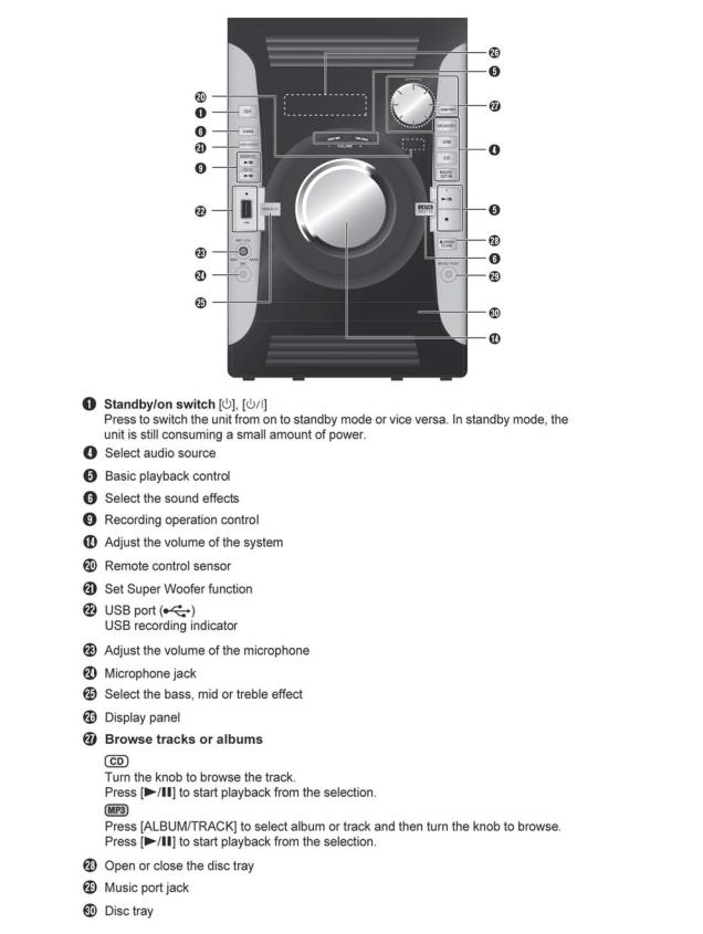
6.2.Main Unit Key Button Operation
16

7 Installation Instructions
7.1.Speaker and A/C Connection
17
8 Service Mode
8.1.Cold-Start
Here is the procedure to carry out cold-start or initialize to shipping mode.
1.Unplug AC power cord
2.Press & hold [POWER] button
3.Plug AC power cord while [POWER] button being pressed FL Display will show “_ _ _ _ _ _ _ _”
4.Release [POWER] button
18

8.2.Doctor Mode Table
8.2.1.Doctor Mode Table 1
|
Item |
|
|
|
|
Key Operation |
||||
|
|
|
FL Display |
|
|
|
||||
|
|
|
|
|
||||||
Mode Name |
Description |
|
|
|
|
|
|
Front Key |
||
|
|
|
|
|
|
|
|
|
|
|
Doctor Mode |
To enter into Doctor Mode |
|
|
|
|
In CD Mode: |
||||
|
|
|
|
|
|
|
|
1. Press [ |
|
] button on |
|
|
|
|
|
|
|
|
|
||
|
|
|
|
|
|
|
|
|
||
|
|
|
|
|
|
|
|
main unit follow by [4] |
||
|
|
|
|
|
|
|
|
and [7] on remote |
||
|
|
|
|
|
|
|
|
|||
|
|
|
|
|
|
|
|
control. |
||
|
|
|
|
|
|
|
|
2. To exit, press [DELETE] |
||
|
|
|
|
|
|
|
|
button on remote control |
||
|
|
|
|
|
|
|
|
|||
|
|
|
|
|
|
|
|
or, press [POWER, /I] button |
||
|
|
|
|
|
|
|
|
on Main Unit |
||
|
|
|
|
|
|
|
|
|
|
|
EEPROM |
Displaying of |
|
|
|
|
In CD mode: |
||||
|
|
|
|
1. Enter Doctor Mode |
||||||
checksum |
1. Year Develop. |
|
|
|
|
|||||
|
|
|
|
|
|
|
||||
check |
2. Model Type. |
|
|
|
|
|
|
|
|
|
|
3. ROM Type. |
|
|
|
|
|
|
|
|
|
|
4. Firmware Version. |
|
|
|
|
|
|
|
|
|
|
|
|
|
|
|
|
|
|
||
|
|
|
|
|
||||||
|
1 2 3 |
|
4 (Decimal) |
|||||||
|
|
Version No. (001 ~ 999) |
specific for each firmware |
|||||||
Cold Start |
To active cold start upon next AC |
|
power up when reset start is |
|
execute the next time . |
In Doctor Mode :
1.Press [SLEEP] button on remote control.
19

8.2.2.Doctor Mode Table 2
|
Item |
|
FL Display |
|
|
|
Key Operation |
|||||||||||||
|
|
|
|
|
|
|
|
|
|
|
|
|
|
|
|
|
|
|||
Mode Name |
Description |
|
|
|
Front Key |
|||||||||||||||
|
|
|
|
|
|
|
||||||||||||||
|
|
|
|
|
|
|
|
|
|
|
|
|
|
|
|
|
|
|
|
|
Volume Setting |
To check the volume setting of a main |
|
|
|
|
|
|
|
In Doctor Mode : |
|
|
|||||||||
|
|
|
|
|
|
|
|
|
||||||||||||
Check |
unit. |
|
|
|
|
|
|
|
|
|
||||||||||
|
|
|
|
|
|
|
1. Press [7], [8], [9] button |
|||||||||||||
|
|
|
|
|
|
|
|
|
||||||||||||
|
|
|
|
|
|
|
|
|
on remote control. |
|||||||||||
|
|
|
|
|
|
|
|
|
|
|
|
|
|
|
|
|
|
|
|
|
|
|
Press [7]: VOL50 |
|
Vo lume |
|
|
|
|
|
|
|
|
|
|||||||
|
|
Press [8]: VOL35 |
|
|
|
|
|
|
|
|
|
|
||||||||
|
|
|
|
|
|
|
|
|
|
|
|
|||||||||
|
|
|
|
|
|
|
|
|
|
|
|
|
|
|
|
|
||||
|
|
Press [9]: VOL0 |
|
|
|
|
|
|
|
|
|
|
|
|
|
|
|
|||
|
|
|
|
|
|
|
|
|
|
|
|
|
|
|
|
|
|
|
|
|
FL Display |
To check the FL segment display |
|
|
|
|
|
|
|
In Doctor mode : |
|
|
|||||||||
|
|
|
|
|
|
|
1. Press [1] button on |
|||||||||||||
Check |
All segment will light up while all LED |
|
|
|
|
|
|
|
||||||||||||
|
|
|
|
|
|
|
remote control. |
|
|
|||||||||||
|
blink at 0.5s,intervals.(if any) |
|
|
|
|
|
|
|
|
|
||||||||||
|
|
|
|
|
|
|
|
|
|
|
|
|
|
|
|
|
|
|
|
|
|
|
|
|
|
|
|
|
|
2. To cancel, press [0 ] |
|||||||||||
|
|
|
|
|
|
|
|
|
on remote control. |
|||||||||||
|
|
|
|
|
|
|
|
|
|
|
|
|
|
|
|
|
|
|
|
|
BRS11C Reliability |
To determine CD Mechanism BRS11C |
|
|
|
|
|
|
|
In Doctor Mode : |
|
|
|||||||||
|
|
|
|
|
|
|
|
|
||||||||||||
Test (Traverse) |
Access Inner & Outer disc operation. |
|
|
|
|
|
|
|
1. Press [10] |
|
|
|
[1] |
|
|
|
[2] button |
|||
|
|
|
|
|
|
|
|
|
|
|
|
|||||||||
|
|
|
|
|
|
|
|
|
on remote control. |
|||||||||||
|
In this mode,ensure the CD is in the |
|
|
|
|
|
|
|
|
|
|
|
|
|
|
|
|
|
|
|
|
|
|
|
|
|
|
|
|
|
|
|
|
|
|
|
|
|
|
|
|
|
main unit. |
|
The counter will |
|
|
|
|
|
|
|
|
|
|
|
|
|
|
|
|
|
|
|
|
|
|
|
|
|
|
|
|
|
|
|
|
|
|
|
|
|
|
|
|
|
increment by one . |
|
|
|
|
|
|
|
|
|
|
|
|
|
|
|
||
|
|
|
When reach 9999 |
|
|
|
|
|
|
|
|
|
|
|
|
|
|
|
||
|
|
|
will change to 0000 |
|
|
|
|
|
|
|
|
|
|
|
|
|
|
|
||
|
|
|
Cancellation Display |
|
|
|
|
|
|
|
|
|
|
|
|
|
|
|
||
|
|
|
|
|
|
|
|
|
2. To cancel, press [0] |
|||||||||||
|
|
|
|
|
|
|
|
|
||||||||||||
|
Note: Refer to Section 8.3 Fig 2. for |
|
|
|
|
|
|
|
on remote control. |
|||||||||||
|
|
|
|
|
|
|
|
|
|
|
|
|
|
|
|
|
|
|
|
|
|
process flow . |
|
|
|
|
|
|
|
|
|
|
|
|
|
|
|
|
|
|
|
|
|
|
|
|
|
|
|
|
|
|
|
|
|
|
|
|
|
|
|
|
BRS11C Reliability |
To determine CD Mechanism Unit |
|
|
|
|
|
|
|
In Doctor Mode : |
|
|
|||||||||
|
|
|
|
|
|
|
|
|
||||||||||||
Test |
(BRS11C) Open/Close & Access Inner & |
|
|
|
|
|
|
|
1. Press [10] |
|
|
[1] |
|
|
|
[5] button |
||||
|
|
|
|
|
|
|
|
|
|
|
|
|||||||||
(Combination) |
Outer Disc Operation. |
|
|
|
|
|
|
|
on remote control. |
|||||||||||
|
In this mode,ensure the CD is in the |
|
|
|
|
|
|
|
|
|
|
|
|
|
|
|
|
|
|
|
|
|
|
|
|
|
|
|
|
|
|
|
|
|
|
|
|
|
|
|
|
|
main unit. |
|
The counter will |
|
|
|
|
|
|
|
|
|
|
|
|
|
|
|
|
|
|
|
|
|
|
|
|
|
|
|
|
|
|
|
|
|
|
|
|||
|
|
|
increment by one . |
|
|
|
|
|
|
|
|
|
|
|
|
|
|
|
||
|
|
|
When reach 9999 |
|
|
|
|
|
|
|
|
|
|
|
|
|
|
|
||
|
|
|
will change to 0000 |
|
|
|
|
|
|
|
|
|
|
|
|
|
|
|
||
|
|
|
Cancellation Display |
|
|
|
|
|
|
|
|
|
|
|
|
|
|
|
||
|
Note: Refer to Section 8.3 Fig 3. for |
|
|
|
|
|
|
|
2. To cancel, press [0] |
|||||||||||
|
|
|
|
|
|
|
|
|||||||||||||
|
|
|
|
|
|
|
|
on remote control . |
||||||||||||
|
process flow . |
|
|
|
|
|
|
|
||||||||||||
|
|
|
|
|
|
|
|
|
|
|
|
|
|
|
|
|
|
|
|
|
|
|
|
|
|
|
|
|
|
|
|
|
|
|
|
|
|
|
|
|
|
BRS11C Reliability |
To determine CD Mechanism Unit |
|
|
|
|
|
|
|
In Doctor Mode : |
|
|
|||||||||
|
|
|
|
|
|
|
|
|
||||||||||||
Test (Loading) |
(BRS11C) Open/Close operation. |
|
|
|
|
|
|
|
1. Press [10] |
|
|
|
[2] |
|
|
|
|
[1] button |
||
|
|
|
|
|
|
|
|
|
|
|
|
|
||||||||
|
|
|
|
|
|
|
|
|
on remote control. |
|||||||||||
In this mode, the tray will open & close.
The counter will increment by one . When reach 9999 will change to 0000
Cancellation Display
2. To cancel, press [0]
on remote control.
Note: Refer to Section 8.3 Fig 1 for
process flow .
20
8.2.3.Doctor Mode Table 3
|
Item |
|
|
FL Display |
|
|
|
|
|
|
|
|
Key Operation |
||||||||||||
|
|
|
|
|
|
|
|
|
|
|
|
|
|
|
|
|
|
|
|
|
|||||
Mode Name |
Description |
|
|
|
|
|
|
|
|
|
|
Front Key |
|||||||||||||
|
|
|
|
|
|
|
|
|
|
|
|
|
|
|
|||||||||||
|
|
|
|
|
|
|
|
|
|
|
|
|
|
|
|
|
|
|
|
|
|
|
|
|
|
CD |
i. Function: To display result of |
|
|
|
|
|
|
|
|
|
|
|
|
|
|
|
In Doctor Mode: |
||||||||
SelfAdjustment |
self-adjustment for CD . |
|
|
|
|
|
|
|
|
|
|
|
|
|
|
|
|
1. Press [10] |
|
[1] |
|
[4] button |
|||
|
|
|
|
|
|
|
|
|
|
|
|
|
|
|
|
|
|
||||||||
(AJST) |
This is used for servicing |
|
|
|
|
|
|
|
|
|
|
|
|
|
|
|
|
on remote control . |
|||||||
Result Display |
and analysis. |
|
|
|
|
|
|
|
|
|
|
|
|
|
|
|
|
|
|
|
|
|
|||
|
|
|
|
|
|
|
|
|
|
|
|
|
|
|
|
|
|
|
|
|
|
|
|
|
|
|
|
|
|
|
|
|
|
|
Display of auto |
|
|
|
|
|
|
|
|
|
|
|
|||||
|
|
|
|
|
|
|
|
|
|
|
|
|
|
|
|
|
|
|
|
||||||
|
|
|
|
|
|
|
|
|
adjustment result |
|
|
|
|
|
|
|
|
|
|
||||||
|
|
|
Reference table: |
|
|
|
|
|
|
|
|
|
|
|
|
|
|
|
|
|
|
|
|
||
|
|
|
|
|
|
|
|
|
|
|
|
|
|
|
|
|
|
|
|
|
|
|
|
|
|
|
|
|
|
|
ERROR Code |
0 |
1 |
2 |
|
4 |
6 |
8 |
A |
C |
E |
F |
|
|
|
|
|
|
|||
|
|
|
Status |
|
|
||||||||||||||||||||
|
|
|
Condition |
|
|
|
|
|
|
|
|
|
|
|
|
|
|
|
|
|
|
|
|
||
|
|
|
AOC1/AOC2 |
O |
|
|
O |
O |
O |
O |
O |
O |
O |
- |
|
|
|
|
|
|
|||||
|
|
|
|
|
|
|
|
|
|
|
|
|
|
|
|
|
|
|
|
|
|
|
|||
|
|
|
ABC2/ABC1 |
O |
- |
X |
|
O |
X |
O |
X |
O |
X |
- |
|
|
|
|
|
|
|||||
|
|
|
|
|
|
|
|
|
|
|
|
|
|
|
|
|
|
|
|
|
|
|
|||
|
|
|
2nd AOC1 |
O |
- |
O |
|
X |
X |
O |
O |
X |
X |
- |
|
|
|
|
|
|
|||||
|
|
|
FAGC/T AGC |
O |
- |
O |
O |
O |
X |
X |
X |
X |
- |
|
|
|
|
|
|
||||||
|
|
|
|
|
|
|
|
|
|
|
|
|
|
|
|
|
|
|
|
|
|
|
|||
|
|
|
|
|
AGC2 |
O |
- |
O |
O |
O |
O |
O |
O |
O |
|
|
|
|
|
|
|
||||
|
|
|
|
|
|
|
|
|
|
|
|
|
|
|
|
|
|
|
|
|
|
|
|
|
|
|
|
|
O: OK ; |
|
|
|
|
|
|
|
|
|
|
|
|
|
|
|
|
|
|
|
|
||
|
|
|
X: NG (In case that time out happens.) |
|
|
|
|
|
|
2. To cancel, press [0] |
|||||||||||||||
|
|
|
: Either one of FO AOC, TR AOC and |
|
|
|
|
|
|
on remote control . |
|||||||||||||||
|
|
|
FO coarse AGC is NG . |
|
|
|
|
|
|
|
|
|
|
|
|
|
|||||||||
|
|
|
: If the AGC is NG (ignore others). |
|
|
|
|
|
|
|
|
|
|
|
|
||||||||||
|
|
|
|
|
|
|
|
|
|
|
|
|
|
|
|
|
|
|
|
|
|
|
|
|
|
CD LSI |
|
|
|
|
|
|
|
|
|
|
|
|
|
|
|
|
|
In Doctor Mode : |
|||||||
For checking CD LSI Version and |
|
|
|
|
|
|
|
|
|
|
|
|
|
|
|
|
|
||||||||
Ve rsion Check |
checksum information. |
|
|
|
|
|
|
|
|
|
|
|
|
|
|
|
|
1. Press [4] button |
|||||||
|
|
|
|
|
|
|
|
|
|
|
|
|
|
|
|
|
|
|
|
|
on remote control . |
||||
|
|
|
|
|
|
|
|
|
|
|
|
|
|
|
|
|
|
|
|||||||
|
|
|
Version (Decimal ) |
|
|
|
C hecksum (Hex) |
|
|
|
|
|
|
|
|
|
|||||||||
|
|
|
|
|
|
|
|
|
|
|
|
|
|
|
|
|
|
|
|
|
2. To cancel, press [0] |
||||
|
|
|
(Display 1) |
|
|
|
|
|
|
|
|
|
|
|
|
|
|
|
on remote control . |
||||||
|
|
|
|
|
|
|
|
|
|
|
|
|
|
|
|
|
|
|
|
|
|
|
|||
|
|
|
|
|
|
|
|
|
|
|
|
|
|
|
|
|
|
|
|
|
|
|
|
|
|
|
|
|
|
|
|
|
|
|
|
|
|
|
|
|
|
|
|
|
|
|
|
|
|
|
|
|
after |
ROM Version |
2 sec |
(Display 2)
Year ROM Version (Decimal)
Develop Type
21

8.3.Reliability Test Mode (CD Mechanism Unit (BRS11C))
Below is the process flow chart of the aging test for the CD Mechanism Unit (BRS11C).
OPEN
Operation
OPEN wait for 1 s
CLOSE |
Count up |
|
Operation |
|
|
|
|
|
|
|
|
CLOSE wait
for 4 s
Fig. 1. Reliability Test (Loading)
First Track
Access
First Track
Play 10 s
Last Track
Access
Last Track
Play 10 s
Open
Operation
Open wait
for 1 s
CLOSE
Operation
First Track
Access
First Track
Play 5 s
Last Track
Access
|
Last Track |
Count up |
|
|
Play 5 s |
|
|
|
|
|
|
|
|
|
|
Fig. 2. Reliability Test (Traverse)
Count up
Fig. 3. Reliability Test (Combination)
22

8.4.Self-Diagnostic Mode
|
Item |
|
|
FL Display |
Key Operation |
||||||||
|
|
|
|
|
|
|
|
|
|
|
|||
Mode Name |
Description |
|
|
|
|
|
|
Front Key |
|||||
|
|
|
|
|
|
|
|
|
|
|
|
|
|
Self Diagnostic |
To enter into self diagnostic checking |
|
|
|
|
|
Step 1: Select CD mode |
||||||
|
|
|
|
|
|||||||||
Mode |
|
|
|
|
|
|
(Ensure no disc is inserted). |
||||||
|
|
|
|
|
|
|
Step 2: Press & hold [ |
|
] follow by |
||||
|
|
|
|
|
|
|
|
||||||
|
|
|
|
|
|
|
[ / |
|
|
|
] on main unit for 2 |
||
|
|
|
|
|
|
|
|
|
|
||||
|
|
|
|
|
|
|
seconds. |
||||||
|
|
|
|
|
|
|
|
|
|
|
|
|
|
Error code |
System will perform a check on any |
|
Example: |
|
|
|
Step 1: In self diagnostic mode, |
||||||
information |
unusual/error code from the memory |
|
|
|
|
|
Press [ |
|
] on main unit. |
||||
|
|
|
|
|
|
||||||||
|
|
|
|
|
|
|
To exit, press [^/I] on main |
||||||
|
|
|
|
|
|
|
unit or remote control. |
||||||
|
|
|
|
|
|
|
|
|
|
|
|
|
|
Delete error |
To clear the stored in memory |
|
|
|
|
|
Step 1: In self diagnostic mode, |
||||||
code |
(EEPROM IC) |
|
|
|
|
|
Press [0] on remote control. |
||||||
|
|
|
|
|
|
|
To exit, press [^/I] on main |
||||||
|
|
|
|
|
|
|
unit or remote control. |
||||||
|
|
|
|
|
|
|
|
|
|
|
|
|
|
|
|
|
|
|
|
|
|
|
|
|
|
|
|
8.5.Self-Diagnostic Error Code Table
Self-Diagnostic Function (Refer Section 8.4. Self-Diagnostic Mode) provides information on any problems occurring for the unit and its respective components by displaying the error codes. These error code such as U**, H** and F** are stored in memory and held unless it is cleared.
The error code is automatically display after entering into self-diagnostic mode.
8.5.1.Power Supply Error Code Table
23

8.5.2.CD Mechanism Error Code Table (CD Mechanism Unit (BRS11C))
Error Code |
Diagnostic Contents |
Descriptionof error |
|
Automatic FL Display |
|
|
|
Remarks |
|
|
|
|
|
|
|
|
|
CD H15 |
CD Open Abnormal |
During operation |
|
|
|
Press [ |
|
] on main unit for |
|
|
|
||||||
|
|
POS_SW_R On fail to be |
|
|
|
|
||
|
|
|
|
|
next error. |
|||
|
|
detected with 4 sec. Error |
|
|
|
|||
|
|
|
|
|
|
|
|
|
|
|
No. shall be clear by force |
|
|
|
|
|
|
|
|
or during cold start. |
|
|
|
|
|
|
|
|
|
|
|
|
|
|
|
CD H16 |
CD Closing Abnormal |
During operation |
|
|
|
Press [ |
|
] on main unit for |
|
|
|||||||
|
|
|||||||
|
|
POS_SW_CEN On fail to |
|
|
|
next error. |
||
|
|
be detected with 4 sec. |
|
|
|
|
|
|
|
|
|
|
|
|
|
||
|
|
Error No. shall be clear by |
|
|
|
|
|
|
|
|
force or during cold start. |
|
|
|
|
|
|
|
|
|
|
|
|
|
|
|
F26 |
Communication between |
During switch to CD func- |
|
|
|
Press [ |
|
] on main unit for |
|
|
|||||||
|
|
|||||||
|
CD servo LSI and micro-p |
tion, if SENSE = “L” within |
|
|
|
next error. |
||
|
abnormal. |
failsafe time of 20ms. |
|
|
|
|
|
|
|
|
|
|
|
|
|||
|
|
|
|
|
|
|
|
|
8.6.Sales Demonstration Lock Function
8.6.1.Entering into sales Demo Mode
Here is the procedures to enter into Sales Demonstration Lock. Step 1: Turn on the unit.
Step 2: Select to any mode function.
Step 3: Press [ OPEN/CLOSE] key then [
 /
/  ] key at the same time,press and hold both [
  OPEN/CLOSE] and [
  /
/  ] keys for 5 sec. Step 4: The display will show upon entering into this mode for 2 sec..
Note: [ OPEN/CLOSE] button is invalid and the main unit displays “LOCKED” while the lock function mode is entered.
8.6.2.Cancellation
Step 1: Turn on the unit.
Step 2: Select to any mode function.
Step 3: Press [ OPEN/CLOSE] key then [
 /
/  ] key at the same time,press and hold both [
  OPEN/CLOSE] and [
  /
/  ] keys for 5 sec. Step 4: The display will show upon entering into this mode for 2 sec..
24
9 Troubleshooting Guide
9.1.Part Location
9.1.1.SMPS P.C.B.
AC Inlet :
P5701
|
|
Fuse : |
|
|
F1 |
|
SMPS Control IC : |
Photocoupler : |
|
IC5799 |
|
|
PC5702, PC5799 |
|
|
|
|
Switching Regulator IC : |
Thermistor : |
|
IC5701 |
Sub Transformer : |
|
|
TH5861 |
D5798 |
Sub Transformer : 
T5751
Rectifier Diode :
 D5801, D5802
Photocoupler :
PC5720
Connector :
Main Tr ansformer :
T5701
CN5802
Fig. 1 SMPS P.C.B.
25

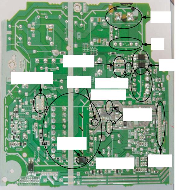
9.1.2.Main P.C.B. (Front Side)
Fig. 2 Main P.C.B. (Front Side)
26

Resistor Defective |
Resistor Defective |
Resistor Defective |
|
R5805 |
R5804 |
R5702 |
|
|
Resistor Defective |
Resistor Defective |
|
Resistor Defective |
R5802 |
|
R5705 |
|
|
Resistor Defective |
|
R5803 |
|
|
|
|
|
|
R5704 |
|
|
|
Resistor Defective |
|
|
|
R5703 |
Audio Digital Amp IC |
|
Audio Digital Amp IC |
|
IC5800 |
|
|
IC5700 |
D2004
Regulator Circuit
L2000  Voltage Regulator IC
IC2011
Regulator Circuit |
Regulator Circuit |
Q2022 |
L2001 |
Voltage Regulator IC
IC2010
Fig. 3 Main P.C.B. (Back Side)
27

9.1.3.D-AMP P.C.B.
Resistor Defective |
Resistor Defective |
R5922 |
R5921 |
Resistor Defective
R5917
Audio Digital
Amp IC: IC5900
Resistor Defective
R5905
Fig. 4 D-Amp P.C.B.
28
9.2.Troubleshooting Guide for F61 and/or F76
This section illustrates the checking procedures when upon detecting the error of “F61” and/or “F76” after power up of the unit. It is for purpose of troubleshooting and checking in SMPS, Main & D-Amp P.C.B.
Symptom |
|
Checking Items |
|
Possible Fault(s) |
Remarks |
Set cannot ON |
1 |
AC Cord |
1 |
AC Cord Faulty, Loose connection. |
Refer to |
|
2 |
AC Inlet, P5701 |
2 |
P5701 solder crack, dry joint. |
Section 9.1.1 |
|
3 |
Fuse, F1 |
3 |
Fuse, F1 Open . |
Fig. 1. SMPS |
|
4 |
Photocoupler |
4 |
PC5702/PC5799 solder crack. |
P.C.B. |
|
|
PC5702, PC5799 |
|
Dry joint, short circuit, open circuit. |
|
|
5 |
Switching Regulator |
5 |
IC5701 Faulty . |
|
|
|
IC, IC5701 |
|
|
|
|
6 |
Main Transformer T5751 |
6a |
T5751 Faulty. |
|
|
|
|
6b |
Switching Mode Power Supply Control IC (IC5799) faulty. |
|
|
|
|
6c |
D5798 faulty. |
|
|
|
|
|
|
|
Set can ON |
1 |
Speaker Output |
1 |
Faulty speaker unit, Loose connection, Short. |
Refer to |
then F61 |
|
|
|
|
Section 9.1.2 |
|
2 |
D -AMP circuit |
2a |
D-AMP IC, IC5700, IC5800, IC5900 defective. |
Fig. 3. Main P.C.B. |
|
|
|
|
(Check DC voltage at speaker terminals, 3V and above defective) |
and Section 9.1.3 |
|
|
|
2b |
DC Voltage ok but no sound, check DC Voltage at Pin 1 . |
Fig. 4. D-Amp |
|
|
|
|
5V ok condition, 2.5V or 0V defective. |
P.C.B. |
|
|
|
2c |
2a, 2b ok but no sound, check PWM waveform at Pin 10 and Pin 14 . |
|
|
|
|
|
If no PWM, 12 resistors defective. |
|
|
|
|
|
For IC5700 (R5702, R5703, R5704, R5705). |
|
|
|
|
|
For IC5800 (R5802, R5803, R5804, R5805). |
|
|
|
|
|
For IC5900 (R5905, R5917, R5921, R5922). |
|
|
|
|
|
|
|
Set can ON |
1 |
Main Transformer T5701 |
1a |
Short circuit between Pin 11 and Pin 12 . |
Refer to |
then F76 |
|
|
1b |
Short circuit between Pin 13 and Pin 14 . |
Section 9.1.1 |
|
|
|
1c |
Short circuit between Pin 16 and Pin 17 . |
Fig. 1. SMPS |
|
|
|
|
|
P.C.B. |
|
|
|
|
|
|
|
2 |
Regulator Circuits |
2a |
IC2010 faulty (No +9V output). |
Refer to |
|
|
|
2b |
L2000 Open. |
Section 9.1.2 |
|
|
|
2c |
Q2022 faulty (No +5V output). |
Fig. 2. and Fig.3. |
|
|
|
2d |
IC2014 faulty (No +3.3V output). |
Main P.C.B. |
|
|
|
2e |
IC2011 faulty (No +5V output). |
|
|
|
|
2f |
L2001 Open. |
|
|
|
|
|
|
|
|
3 |
Photocoupler |
3 |
PC5720 solder crack, |
Refer to |
|
|
PC5720 |
|
Dry joint, short circuit, open circuit. |
Section 9.1.1 |
|
|
|
|
|
Fig. 1. SMPS P.C.B. |
Set can ON |
1 |
Rectifier Diode D5801 |
1a |
Improper contact between D5801 to Heatsink. |
Refer to Section |
working normally |
|
Rectifier Diode D5802 |
|
Improper contact between D5802 to Heatsink. |
|
|
|
9.1.1 Fig. 1. SMPS |
|||
for some time |
2 |
Thermistor TH5860, |
1b |
Set trigger temperature protection. |
P.C.B. |
then F76 |
|
TH5861 |
|
|
|
|
|
|
|
|
|
29

9.3.D-Amp IC Operation & Control
30
 Loading...