


Service Manual
TOP NEXT
ORDER NO. MD0110223C1
A6
CD Stereo System
• SA-AK300 Colour
(K)... Black Type
(S)... Silver Type
Area
(P)... U.S.A.
(PC)... Canada
TAPE SECTION :
SG-2W MECHANISM SERIES
CD SECTION :
RAE0152Z-3 TRAVERSE DECK SERIES
|
Specifications |
AMPLIFIER SECTION |
|
Power output |
|
10% Total harmonic distortion |
|
3 kHz - 16 kHz, both channels driven |
|
(HIGH) |
45 W per channel (6Ω) |
60 Hz - 3 kHz, both channels driven |
|
(LOW) |
45 W per channel (6Ω) |
Total Bi-Amp power |
90 W per channel |
Power output |
|
10% Total harmonic distortion |
|
10 kHz, both channels driven |
|
(HIGH) |
48 W per channel (6Ω) |
1 kHz, both channels driven |
|
(LOW) |
52 W per channel (6Ω) |
Total Bi-Amp power |
100 W per channel |
Input sensitivity |
|
AUX |
250 mV |
Input Impedance |
|
AUX |
13.3 kΩ |
FM TUNER SECTION |
|
Frequency range |
87.9 - 107.9 MHz (200 kHz steps) |
|
87.5 - 108.0 MHz (100 kHz steps) |
Sensitivity |
2.5μV (IHF) |
S/N 26 dB |
2.2μV |
Antenna terminal(s) |
75Ω (unbalanced) |
AM TUNER SECTION |
|
Frequency range |
520 - 1710 kHz (10 kHz steps) |
Sensitivity |
|
S/N 20 dB (at 1000 kHz) |
560μV/m |
CASSETTE DECK SECTION |
|
Track system |
4 track, 2 channel |
Heads |
|
Record/playback |
Solid permalloy head |
SCHEMA*99

Erasure |
Double gap ferrite head |
Motor |
DC servo motor |
Recording system |
AC bias 100 kHz |
Erasing system |
AC erase 100 kHz |
Tape speed |
4.8 cm/s |
Frequency response (+3 dB, -6 dB at DECK OUT) |
|
NORMAL (TYPE I) |
35 Hz - 14 kHz |
S/N |
50 dB (A weighted) |
Wow and flutter |
0.18% (WRMS) |
Fast forward and rewind time |
Approx. 120 seconds with |
|
C-60 cassette tape |
CD SECTION |
|
Sampling frequency |
44.1 kHz |
Decoding |
16 bit linear |
Beam source/wave length |
Semiconductor laser/780 nm |
Number of channels |
Stereo |
Frequency response |
20 Hz - 20 kHz (+1, -2 dB) |
Wow and flutter |
Below measurable limit |
Digital filter |
8 fs |
D/A converter |
MASH (1 bit DAC) |
GENERAL |
|
Power supply |
AC 120 V, 60Hz |
Power consumption |
165 W |
Power consumption in standby mode |
|
|
0.34 W |
Dimensions (W x H x D) |
250 x 315 x 345 mm |
|
(9 27/32” x 12 13/32” x 13 19/32”) |
Mass |
7.4 kg (16.3 lb) |
SYSTEM |
|
SC-AK300(P) |
Music Center: SA-AK300(P) |
|
Speaker: SB-AK300(P) |
SC-AK300(PC) |
Music Center: SA-AK300(PC) |
|
Speaker: SB-AK300(P) |
Notes: |
|
1.Specifications are subject to change without notice. Mass and dimensions are aproximate.
2.Total harmonic distortion is measured by the digital spectrum analyzer.
3.The labels“HIGH” and“LOW” on the rear of the speakers refer to High frequency and Low frequency.
©2001 Matsushita Electronics (S) Pte. Ltd. All rights reserved. Unauthorized copying and distribution is a violation of law.
TOP NEXT
SCHEMA*99

9 Self-Diagnostic Function
TOP PREVIOUS NEXT 9.1 Self-diagnostic display
9.2 How to enter the Self-Diagnostic Function
9.3 Cassette Mechanism Test (For error code H01, H02, H03, F01, F02) 9.4 CD Mechanism Test (F15, F26, F16, F17, F27, F28, F29, H15)
9.5 To clear all Error code
9.6 How to get out from Self-Diagnostic function 9.7 Power Amplifier Failure (F61)
TOP PREVIOUS NEXT
SCHEMA*99

9.1 Self-diagnostic display
TOP PREVIOUS NEXT
This unit is equipped with a self-diagnostic display function which, if a problem occurs, will display an error code corresponding to the problem.
Use this function when performing maintenance on the unit.
TOP PREVIOUS NEXT
SCHEMA*99
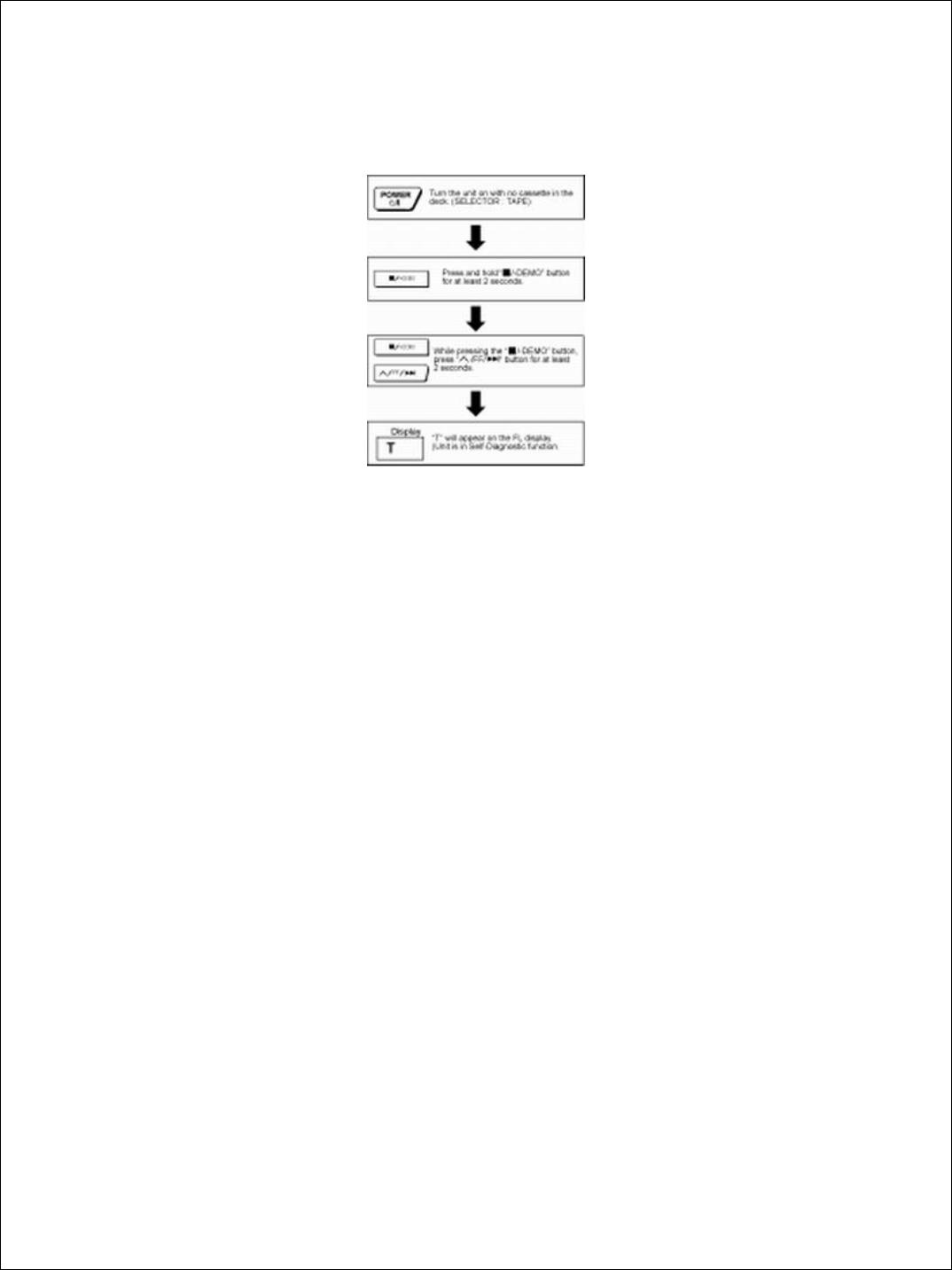
9.2 How to enter the Self-Diagnostic Function
TOP PREVIOUS NEXT
TOP PREVIOUS NEXT
SCHEMA*99

9.3 Cassette Mechanism Test (For error code H01, H02, H03, F01, F02)
TOP PREVIOUS NEXT
1.Press “TAPE, DECK 1/2” to select Deck 2.
2.Load a cassette tape with the erasure prevention tab, remove from left side only and close the cassette holder.
3.Press “FAST FORWARD MEMORY” (Tape will be stop after 2 seconds)
4.Load a cassette tape with the erasure prevention tab, remove from right side only and close the cassette holder.
5.Press “REVERSE FM MODE/BP” (Tape will be stop after 2 seconds)
6.Load a pre-recorded tape with both side record tabs intact and close the cassette holder.
7.Press “PLAY/TUNE/TIME ADJ UP” (After TPS function, tape will stop automatically)
8.Press “REC/STOP” (Tape will not move)
9.Press “STOP/TUNE MODE” to indicate Error code.
¡ If several problem exist, error code will change each time when “ /TUNE MODE” is pressed.
(e.g. H01 → H03 → F01 .....etc.)
10.Press “TAPE, DECK 1/2” to select Deck 1.
11.Repeat step 2 to 9 to test Deck 1. (Tape Deck 1 will not check H02 because of no recording function)
TOP PREVIOUS NEXT
SCHEMA*99

9.4 CD Mechanism Test (F15, F26, F16, F17, F27, F28, F29, H15)
TOP PREVIOUS NEXT
1.Press “CD”.
2.Press “OPEN/CLOSE (1)” and place a CD.
3.Press “OPEN/CLOSE (1)” to close the tray.
4.Press “OPEN/CLOSE (5)” and wait until the tray is open.
5.Press “OPEN/CLOSE (1)” and remove the CD.
6.Press “OPEN/CLOSE (1)” to close the tray.
7.Press “ /TUNE MODE” to indicate Error Code.
¡ If several problem exist, error code will change each time when “ /TUNE MODE” is pressed. (e.g. F15 → F26 → F16 ....etc).
TOP PREVIOUS NEXT
SCHEMA*99

9.5 To clear all Error code
TOP PREVIOUS NEXT
1.Press “STOP/TUNE MODE” button for 5 seconds.
2.FL indicator shows “CLEAR” for 1 second and change to “T”.
TOP PREVIOUS NEXT
SCHEMA*99

9.6 How to get out from Self-Diagnostic function
TOP PREVIOUS NEXT
1. Press “Power” button OFF.
TOP PREVIOUS NEXT
SCHEMA*99

9.7 Power Amplifier Failure (F61)
TOP PREVIOUS NEXT
1. When power amplifier fail, F61 will indicate automatically.
TOP PREVIOUS NEXT
SCHEMA*99
10 Description of Error Code
TOP PREVIOUS NEXT
10.1 Error detection for Cassette Mechanism block
10.2 Error detection for CD/Changer block
10.3 Power Supply related error detection
TOP PREVIOUS NEXT
SCHEMA*99

10.1 Error detection for Cassette Mechanism block
TOP PREVIOUS NEXT
No. |
Error |
ErrorDisplay |
Problem condition |
1 |
MODE SWdetection error |
H01 |
Faulty operation of cassette mechanism.Faulty contact or short-circuit of mechanism mode switch (S951, |
|
|
|
S971). |
2 |
REC INH SWdetection |
H02 |
Recording not possible.Faulty contact or short-circuit of REC INH switch (S974, S975). |
|
error |
|
|
3 |
HALF SWdetection error |
H03 |
Playback cannot perform.Faulty contact or short-circuit of HALF siwtch (S952, S972). |
4 |
Reel Pulsedetection error |
F01 |
The tape advances slightly and then stops.Faulty reel pulse, faulty hole detect IC (IC951, IC971). |
5 |
TPS abnormal |
F02 |
Cassette deck will not perform TPS function.Faulty playback EQ/recording amplifier IC (IC101). |
TOP PREVIOUS NEXT
SCHEMA*99

10.2 Error detection for CD/Changer block
TOP PREVIOUS NEXT
No. |
Error |
ErrorDisplay |
Problem condition |
1 |
REST SW detection error |
F15 |
CD does not function.This error occurs when the Optical Pick Up REST SW (S701) is not |
|
|
|
detected within the specified time (about 8 seconds) |
2 |
CD tray opens automatically |
F16 |
CLAMP switch (S4) NG (Check & Replace) |
3 |
Does not startup when [PLAY]button is pressed |
F17 |
BOTTOM switch (S5) NG (Check & Replace) |
4 |
Transmission error between CDservo LSI and micon |
F26 |
CD does not function.This error occurs when the POWER is ON for the CD block and an error is |
|
|
|
detected after the transmission has started. |
5 |
Startup fails even when youinsert CD or the selected disc tray |
F27 |
Tray 1 detect switch or Tray 2 detect switch NG (Check & Replace) |
|
does not open |
|
|
6 |
Cannot insert CD |
F28 |
Tray 1 detect switch NG (Check & Replace) |
7 |
Cannot eject CD |
F29 |
Check if disc is stuck. Tray 2 detect switch NG (Confirm & Replace) |
8 |
The CD tray closes |
H15 |
CD disc tray detect switch NG (S3) (Check & Replace) |
TOP PREVIOUS NEXT
SCHEMA*99

10.3 Power Supply related error detection
TOP PREVIOUS NEXT
No. |
Error |
ErrorDisplay |
Problem condition |
1 |
POWER AMPoutput abnormal |
F61 |
When POWER is switched on, power become off automatically.During normal operation, if DC DET become L, PCNT shall become |
|
|
|
L and the error display on the left shall be displayed. (IC501) |
TOP PREVIOUS NEXT
SCHEMA*99

11 CD Test Mode Function
TOP PREVIOUS NEXT
This CD test mode is provided to check CD unit without connecting to changer loading mechanism. This mode shall operate CD PLAY with CD unit being connected only and CD Automatic Alignment result is shown on FL display.
11.1 How to set CD test mode
11.2 CD Automatically Adjustment result indication
TOP PREVIOUS NEXT
SCHEMA*99

11.1 How to set CD test mode
TOP PREVIOUS NEXT
TOP PREVIOUS NEXT
SCHEMA*99
11.2 CD Automatically Adjustment result indication
TOP PREVIOUS NEXT
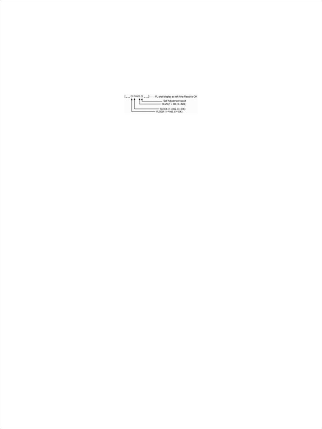
Under CD test mode, pressing the numeric key ‘0’ on the remote controller will display the auto adjustment result. FLOCK, TLOCK and CLVS status shall be shown as below:
During the above display, executing CD PLAY will display auto adjustment result for CD PLAY mode.
TOP PREVIOUS NEXT
SCHEMA*99

15 Block Diagram
TOP PREVIOUS NEXT
TOP PREVIOUS NEXT
SCHEMA*99

16 Schematic Diagram
TOP PREVIOUS NEXT
(All schematic diagrams may be modified at any time with the development of the new technology) Note:
•
•
•
•
•
•
•
•
•
•
•
S701
:Reset switch S600
:Power switch S601
:Display switch S602
:Disc 1 switch S603
:Disc 2 switch S604
:Disc 3 switch S605
:Disc 4 switch S606
:Disc 5 switch S607
:CD open/ Close switch S910
:CD Play switch
S911
: Tape Play switch
SCHEMA*99
 Loading...