


SA-GX770

TeChnics
AV control stereo receiver
SA-GX770/SA-GX670
SA-GX470/SA-G9057
Operating Instructions
The photographs show SA-GX770.
'Before"€oi_neotlng, opetat ng or adjusting this product,
instructions completely.
193-P
Dear Customer
Thank you for purchasing this Technics product.
For optimum performance and safety, please read
these instructions carefully.
These operating instructions are applicable to models SA-
GX770, SA-GX670, SA-GX470 and SA-G9057.
These operating instructions, however, are intended primarily
for model SA-GX770.
Before use
Precautions ........................................ 4
Accessories ........................................ 5
Front panel controls .............................. 6
Connections
Equipment connections .......................... 8
Antenna connections ............................. 10
Speaker connections ............................. 12
Listening
Basic operations .................................. 14
To listen to a desired audio source while watching a
video ................................................. 15
To adjust the tone quality .............................. 15
To mute the sound level ............................... 15
To adjust the sound balance ........................... 15
To emphasize low-frequency sound
m-_f;_et:fwJ07_-'f;wet:(wd0nr_ q ........................... 15
To liSteRthrough headphones ................. : ........ 15
tf sound output stops during use
Ik_;_ _et:fdr40]rk"f;_e]);(,'lrJ[0=rff__ ........................... 15
Listening to radio broadcasts ................... 16
Direct access tuning .................................. !6
Sequential tuning ...................................... " 17
Preset tuning ......................................... 18
.:.-

Adjusting the sound field
Enjoying sound with DOLBY PRO LOGIC ..... 21
SURROUND .......................................... 21
3 STEREO ............................................ 21
Setting the center mode ............................... 21
Adjusting the output level of each speaker ............... 22
Adjusting the delay time Ik'lr__-'le#_q,TJ-z,]-,lql ..... 23
Enjoying with SURROUND or 3 STEREO ................. 23
Recording
Making a recording ............................... 24
Tape recording on the tape deck or digital compact
cassette deck (DCC) ................................... 24
VCR (VCR 1) recording from an audio source ............ 24
Recording from VCR 2 to VCR 1 ........................ 25
To record picture from VCR 2 and sound from
a different audio source ............................... 25
When there seems to be a
problem
About the HELP function
_, . i _, .. 0., ............................. 26
Product service .................................... 26
Troubleshooting guide ........................... 27
Re£erence
Technical specifications ............. Back cover
The model number and serial number of this product can be
found on either the back or the bottom of the unit.
Please note them in the space provided below and retain
them for future reference.
MODEL NUMBER .......................................
SERIAL NUMBER .......................................
CAUTION:
Any unauthorized changes or modifications to this equipment
would void the user's authority to operate this device.
WARNING:
TO REDUCE THE RISK OF FIRE OR
ELECTRIC SHOCK, DO NOT EXPOSE THIS
APPLIANCE TO RAIN OR MOISTURE.
CAUTION:
TO PREVENT ELECTRIC SHOCK MATCH
WIDE BLADE OF PLUG TO WIDE SLOT,
FULLY INSERT.
CAUTION
CAUTION: TO REDUCE THE RISK OF ELECTRIC
SHOCK, DO NOT REMOVE SCREWS.
NO USER-SERVICEABLE PARTS
INSIDE.
REFER SERVICING TO QUALIFIED
SERVICE PERSONNEL.
The lightning flash with arrowhead symbol, within
an equilateral triangle, is intended toalert the user
to the presence of uninsulated "dangerous
voltage" within the product's enclosure that may
be of sufficient magnitude to constitute a risk of
electric shock to persons.
The exclamation point within an equilateral tri-
angle is intended to alert the user to the presence
of important operating and maintenance (ser-
vicing) instructions in the literature accompanying
the appliance.
Beforeusing this unit please read these operating instructions
carefully. Take special care to follow the warnings indicated on
the unit itself as well as the safety suggestions listed below.
Afterwards keep them handy for future reference.
Power Source --The unit should be connected to power sup-
ply only of the type described inthe operating instructions or
as marked on the unit.
2. Polarization -- If the unit is equipped with a polarized AC
power plug (a plug having one blade wider than the other),
that plug will fit into the AC outlet only one way. This is a safe-
ty feature. If you are unable to insert the plug fully into the
outlet, try reversing the plug. If the plug should still fail to fit,
contact your electrician to replace your obsolete outlet. Do
not defeat the safety purpose of the polarized plug.
3. Power Cord Protection -- AC power supply cords should be
routed so that they are not likely to be walked on or pinched
by items placed upon or against them. Never take hold of the
plug or cord if your hand is wet, and always grasp the plug
body when connecting or disconnecting it.
4. Nonuse Periods -- When the unit is not used, turn the power
off. When left unused for a long period of time, the unit should
be unplugged from the household AC outlet.
Installation
Environment
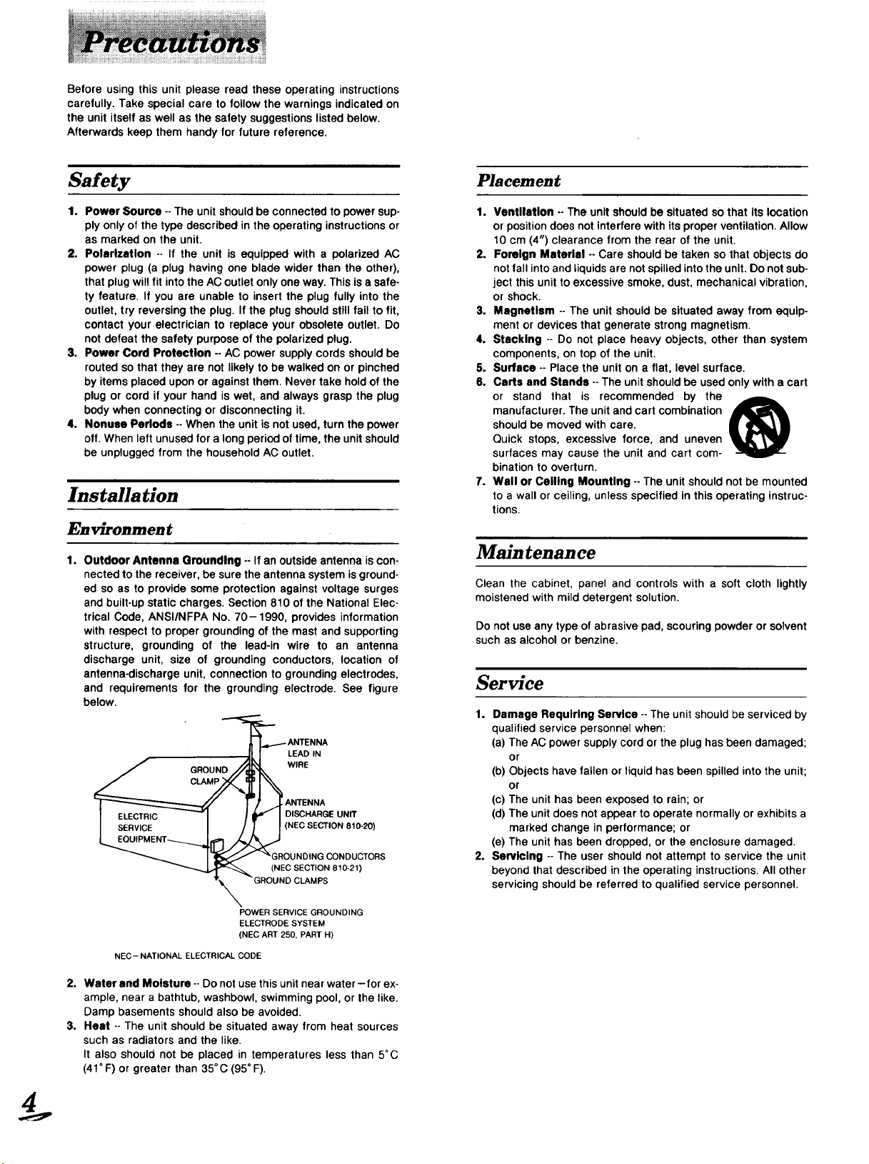
1.
Outdoor Antenna Grounding -- If an outside antenna iscon-
nected to the receiver, be sure the antenna system is ground-
ed so as to provide some protection against voltage surges
and built-up static charges. Section 810 of the National Elec-
trical Code, ANSIINFPA No. 70-1990, provides information
with respect to proper grounding of the mast and supporting
structure, grounding of the lead-in wire to an antenna
discharge unit, size of grounding conductors, location of
antenna-discharge unit, connection to grounding electrodes,
and requirements for the grounding electrode. See figure
below.
'__ANTENNA
_1 1 LEAD IN
f GROUN_ WIRE
]_'""-'__ I )' .,_LANTENNA
l ELECTRIC _1 _ _ I DISCHARGE UNff
L_V_CEE NT_.._[I_ _ (NEC SECTION 810-20)
i.__f _GROUNDINGCONDUCTORS
(NEC SECTION 810-21)
T_ -GROUND CLAMPS
POWER SERVICE GROUNDING
ELECTRODE SYSTEM
(NEC ART 250, PART H)
NEC- NATIONAL ELECTRICAL CODE
2. Water and Moisture-- Do not use this unit near water-for ex-
ample, near a bathtub, washbowl, swimming pool, or the like.
Damp basements should also be avoided.
3. Heat -- The unit should be situated away from heat sources
such as radiators and the like.
It also should not be placed in temperatures less than 5°C
(41°F) or greater than 35°C (95 ° F).
Placement
1. Ventilation -- The unit should be situated so that its location
or position does not interfere with its proper ventilation. Allow
10 crn (4") clearance from the rear of the unit.
2. Foreign Material -- Care should be taken so that objects do
not fall intoand _iquids are not spilled into the unit. Do not sub-
ject this unit to excessive smoke, dust, mechanical vibration,
or shock.
3. Magnetism -- The unit should be situated away from equip-
ment or devices that generate strong magnetism.
4. Stacking -- Do not place heavy objects, other than system
components, on top of the unit.
5. Surface -- Place the unit on a flat, level surface.
6. Carts and Stands -- The unit should be used only with a cart
or stand that is recommended by the _,=
manufacturer. The unit and cart combination
should be moved with care.
Quick stops, excessive force, and uneven
surfaces may cause the unit and cart com-
bination to overturn.
7. Wall or Ceiling Mounting -- The unit should not be mounted
to a wall or ceiling, unless specified in this operating instruc-
tions.
Main tenan ce
Clean the cabinet, panel and controls with a soft cloth lightly
moistened with mild detergent solution.
Do not use any type of abrasive pad, scouring powder or solvent
such as alcohol or benzine.
Service
1.
2.
Damage Requiring Service --The unit should be serviced by
qualified service personnel when:
(a) The AC power supply cord or the plug has been damaged;
or
(b) Objects have fallen or liquid has been spilled into the unit;
or
(c) The unit has been exposed to rain; or
(d) The unit does not appear to operate normally or exhibits a
marked change in performance; or
(e) The unit has been dropped, or the enclosure damaged.
Servicing -- The user should not attempt to service the unit
beyond that described in the operating instructions. All other
servicing should be referred to qualified service personnel.

Pleasecheckandidentifythesupplied
accessories
Listening caution
@
Selecting fine audio equipment such as the unit you've just pur-
chased is only the start of your musical enjoyment. Now it's time
to consider how you can maximize the fun and excitement your
equipment offers. This manufacturer and the Electronic In-
dustries Association's Consumer Electronics Group want you to
get the most out of your equipment by playing it at a safe level.
One that lets the sound come through loud and clear without an-
noying blaring or distortion- and, most importantly, without affec-
ting your sensitive hearing.
Sound can be deceiving. Over time your hearing "comfort level"
adapts to higher volumes of sound. So what sounds "normal"
can actually be loud and harmful to your hearing.
Guard against this by setting your equipment at a safe level
BEFORE your hearing adapts.
To establish a safe level:
• Start your volume control at a low setting.
• Slowly increase the sound until you can hear it comfortably and
clearly, and without distortion.
Once you have established a comfortable sound level:
• Set the dial and leave it there.
Taking a minute to do this now will help to prevent hearing
damage or loss in the future. After all, we want you listening for a
lifetime.
We Want You Listening For A Lifetime
Useclwisely, your new sound equipment will provide a lifetime of
fun and enjoyment. Since hearing damage from loud noise is
often undetectable until it is too late, this manufacturer and the
Electronic Industries Association's Consumer Electronics Group
recommend you avoid prolonged exposure to excessive noise.
This list of sound levels* is included for your protection.
*The level used here is different from that displayed on the
system's display.
Decibel
Level
30
40
50
60
70
80
Example
Quiet library, soft whispers
Living room, refrigerator, bedroom away from traffic
Light traffic, normal conversation, quiet office
Air conditioner at 20 feet, sewing machine
Vacuum cleaner, hair dryer, noisy restaurant
Average city traffic, garbage disposals, alarm clock at
two feet
THE FOLLOWING NOISES CAN BE DANGEROUS UNDER
CONSTANT EXPOSURE
90 Subway, motorcycle, truck traffic, lawn mower
100 Garbage truck, chain saw, pneumatic drill
120 Rock band concert in front of speakers, thunderclap
140 Gunshot blast, jet plane
180 Rocket launching pad
Information courtesy of the Deafness Research Foundation.
D AC power ....................... pc.
supply
cord
1
(For USA: SJA172-A or SJA172-1)
(For Canada: SJA172-A or SJA172)
I--] AM loop antenna set (RSA0010)
• AM loop antenna ........................ 1 pc.
• AM antenna holder ...................... 1 pc.
• Screw .................................. 1 pc.
_] FM indoor antenna (RSA0006) ............... 1 pc.
[] Remote control transmitter 1 pc.
For SA.GX470 For SA-GX7701SA-GX6701
SA-Gg057
(RAK-SA112MH) (RAK-SA723M H)
For details on remotecontrol transmitteropera-
tion, refer to "How to use the remote control
transmitter"in the separate booklet,
D Batteries (UM-4, "AAA", R03) ............... 2 pcs.
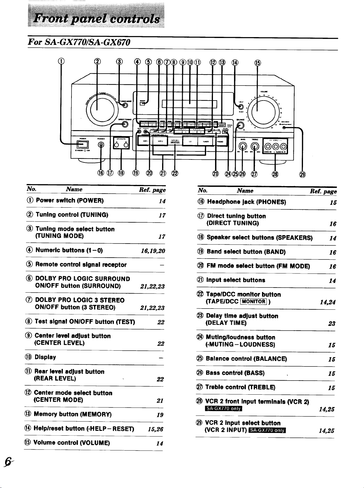
For SA-GX770/SA-GX670
No. Name Re[. page
(_) Power switch (POWER) 14
(_) Tuning control (TUNING) 17
(_ Tuning mode select button
(TUNING MODE) 17
(_) Numeric buttons (1-0) 16,19,20
Remote control signal receptor
(_ DOLBY PRO LOGIC SURROUND
ONIOFF button (SURROUND) 21,22,23
(_ DOLBY PRO LOGIC 3 STEREO
ONIOFF button (3 STEREO) 21,22,23
(_ Test signal ONIOFF button (TEST) 22
(_) Center level adjust button
(CENTER LEVEL) 22
(_ Display
(_ Rear level adjust button
(REAR LEVEL) 22
_) Center mode select button
(CENTER MODE) 21
Memory button (MEMORY) 19
(_ Helplreset button (-HELP-RESET) 15,26
Volume control (VOLUME) 14
i i
No. Name Re[. page
(_ Headphone Jack (PHONES) 15
(_ Direct tuning button
(DIRECT TUNING) 16
Speaker select buttons (SPEAKERS) 14
(_ Band select button (BAND) 16
FM mode select button (FM MODE) 16
Input select buttons 14
(_ TapelDCC monitor button
(TAPE/DCC IMONITOR] ) 14,24
Delay time adjust button
(DELAY TIME)
Mutlnglloudness button
(-MUTING- LOUDNESS)
Balance control (BALANCE)
Bass control (BASS)
Treble control (TREBLE)
VCR 2 front Input terminals (VCR 2)
@
23
®
15
(_ VCR 2 Input select button
(VCR 2 INPUT)
14,25
14,25
.
For SA-GX470/SA-G9057
z I
m_
I I I I
....I....
i , i
I ÷ I
Name Ref. page
(_ Power switch (POWER) 14
(_ Tuning control (TUNING) 18
(_ Band select button (BAND) 16
(_) FM mode select button (FM MODE) 16
(_ Direct tuning button
(DIRECT TUNING) 16
Numeric buttons (1-0) 16,19,20
(_ Remote control signal receptor
(_ DOLBY PRO LOGIC SURROUND
ONIOFF button (SURROUND) 21,22,23
DOLBY PRO LOGIC 3 STEREO
ONIOFF button (3 STEREO) 21,22,23
(_ Test signal ONIOFF button (TEST) 22
Center level adjust button
(CENTER LEVEL) 22
(_ Display
(_ Rear level adjust button
(REAR LEVEL) 22
No.
No. Name Ref. page
(_ Center mode select button
(CENTER MODE) 21
(_ Memory button (MEMORY) 19
(_ Treble control (TREBLE) 15
(_ Bass control (BASS) 15
Headphone Jack (PHONES) 15
(_ Speaker select buttons (SPEAKERS) 14
Input select buttons 14
(_ TapelDCC monitor button
(TAPEIDCC [MONITOR I) 14,24
Muting button (MUTING) 1.9
Balance control (BALANCE) 15
Volume control (VOLUME) 14
7
!:r_l.'f,_let'.fdrMl_'__l[et'.(,'lri
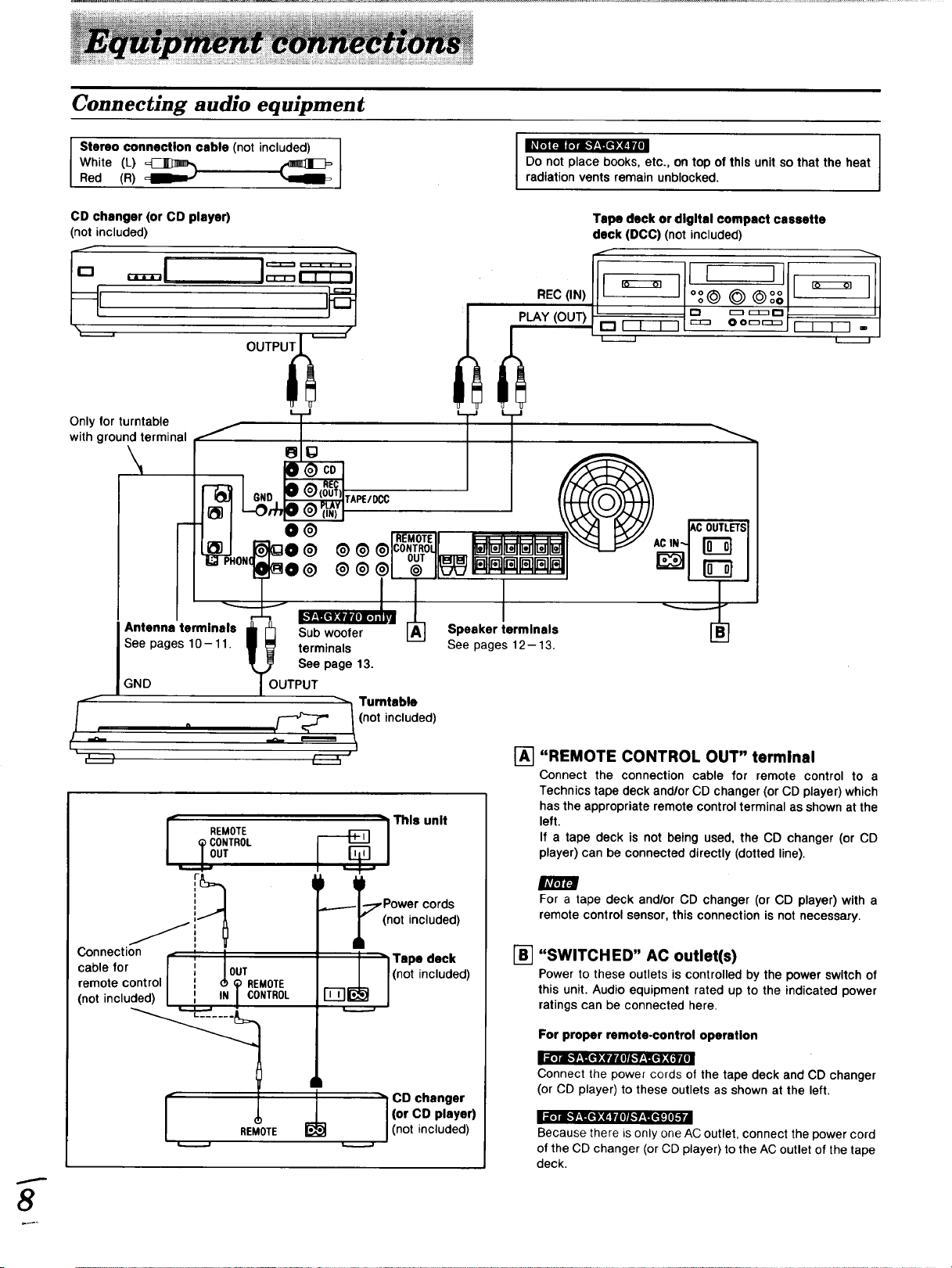
Connecting audio equipment
Stereo connection cable (not included)
White (L) _
Red (R)
_r_llF.iir;_ [,=fl_l[_;=eIt4,
Do not place books, etc., on top of this unit so that the heat
radiation vents remain unblocked.
CD changer (or CD player)
(not included)
OUTPU_ '_-.--f
REC(IN)
PLAY (OUT)
Tape deck or digital compact cassette
deck (DCC) (not included)
iJo l o,
© ©°8
_ r_r_ r-t
O Oor-r_
Only for turntable
with ground terminal
\
I Antenna terminals
See pages 10 -- 11.
GND
S °
/.x_
r REMOTE
(_ CONTROL
._.L OUT
,,
1
Connection _ _ I
cable for / I OUT
remote control l I d__ REMOTE
(not included) / : IN / CONTROL
---_i This unit
t)
,_._..-- ;TPower cords
(not included)
r "1 Tape deck
I'i-i-I I_ J(not included)
" CD changer
(or CD player)
(not included)
[]
"REMOTE CONTROL OUT" terminal
Connect the connection cable for remote control to a
Technics tape deck and/or CD changer (or CD player) which
has the appropriate remote control terminal as shown at the
left.
If a tape deck is not being used, the CD changer (or CD
player) can be connected directly (dotted line).
For a tape deck and/or CD changer (or CD player) with a
remote control sensor, this connection is not necessary.
"SWITCHED" AC outlet(s)
Power to these outlets is controlled by the power switch of
this unit. Audio equipment rated up to the indicated power
ratings can be connected here.
For proper remote-control operation
Connect the power cords of the tape deck and CD changer
(or CD player) to these outlets as shown at the left.
Because there is only one AC outlet, connect the power cord
of the CD changer (or CD player) to the AC outlet of the tape
deck.
8
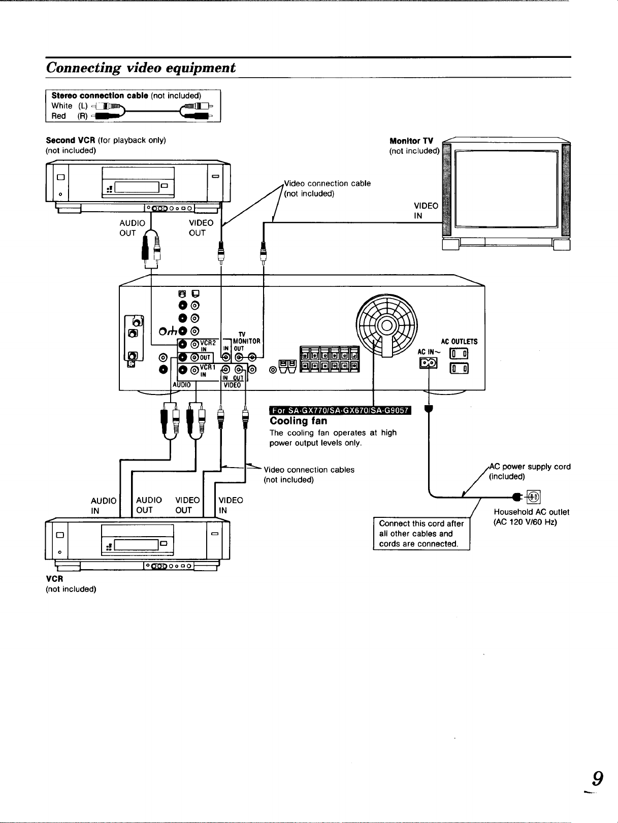
Connecting video equipment
Stereo connection cable (not included) I
White (L)_
I
Red (R)
Second VCR (for playback only)
(not included)
AUDIO
OUT
VIDEO
OUT
connection cable
included)
Monitor TV
(not included)
VIDEO
IN
I_._1
VCR
(not included)
AUDIOIN I
t-:l
' AUDIO VIDEO
OUT OUT
l"V
--'1 MONITOR
iN I OUT
VIDEO
IN
Cooling fan
The cooling fan operates at high
power output levels only,
ACOUTLETS
!
connection cables
(not included)
/_i c power supply cord
ncluded)
Household AC outlet
Connect this cord after (AC 120 V/60 Hz)
all other cables and
cords are connected.
9
 Loading...