


ORDER NO. MD0101009C1
A6
Specifications
■ AMPLIFIER SECTION |
|
Power output |
|
10% Total harmonic distortion |
|
70 Hz-16 kHz, both channels driven |
|
(LOW) |
60 W per channel (6 Ω) |
Power output |
|
10% Total harmonic distortion |
|
1 kHz, both channels driven |
|
(HIGH) |
70 W per channel (6 Ω) |
Input sensitivity |
|
AUX |
250 mV |
Input Impedance |
|
AUX |
13 kΩ |
■ FM TUNER SECTION |
|
Frequency range |
87.9 - 107.9 MHz (200 kHz steps) |
|
87.5 - 108.0 MHz (100 kHz steps) |
Sensitivity |
2.5 µV (IHF) |
S/N 26 dB |
2.2 µV |
Antenna terminal(s) |
75 Ω (unbalanced) |
■ AM TUNER SECTION |
|
Frequency range |
520 - 1710 kHz (10 kHz steps) |
Sensitivity |
|
S/N 20 dB (at 1000 kHz) |
560 µV/m |
CD Stereo System
SA-AK22
Colour
(S)... Silver Type
Area
(P)... U.S.A.
(PC)... Canada
TAPE SECTION :
SG2 MECHANISM SERIES
CD SECTION :
RAE0152Z-3 TRAVERSE DECK SERIES
■ CASSETTE DECK SECTION |
|
Track system |
4 track, 2 channel |
Heads |
|
Record/playback |
Solid permalloy head |
Erasure |
Double gap ferrite head |
Motor |
DC servo motor |
Recording system |
AC bias 100 kHz |
Erasing system |
AC erase 100 kHz |
Tape speed |
4.8 cm/s |
Frequency response (+3 dB, -6 dB at DECK OUT) |
|
HIGH (TYPE II) |
35 Hz - 14 kHz |
S/N |
50 dB (A weighted) |
Wow and flutter |
0.18 % (WRMS) |
Fast forward and rewind time |
Approx. 120 seconds with |
|
C-60 cassette tape |
■ CD SECTION |
|
Sampling frequency |
44.1 kHz |
Decoding |
16 bit linear |
Beam source/wave length |
Semiconductor laser/780 nm |
Number of channels |
Stereo |
Frequency response |
20 Hz - 20 kHz (+1, -2 dB) |
Wow and flutter |
Below measurable limit |
Digital filter |
8 fs |
© 2001 Matsushita Electronics (S) Pte. Ltd. All rights reserved. Unauthorized copying and distribution is a violation of law.
SA-AK22 |
|
|
|
|
D/A converter |
MASH (1 bit DAC) |
SC-AK22(P) |
Music Center: SA-AK22(P) |
|
■ GENERAL |
|
|
Speaker: SB-AK22(P) |
|
Power supply |
AC 120 V, 60Hz |
SC-AK22(PC) |
Music Center: SA-AK22(PC) |
|
Power consumption |
155 W |
|
Speaker: SB-AK22(P) |
|
Dimensions (W x H x D) |
250 x 332 x 316 mm |
Notes: |
|
|
|
|
9 27/32” x 13 1/16” x 12 7/16” |
1. Specifications are subject to change without notice. Mass and |
|
Mass |
(7.6 kg) 16.8 lb |
dimensions are aproximate. |
|
|
|
|
|||
■ SYSTEM |
2. Total harmonic distortion is measured by the digital spectrum |
|
analyzer. |
||
|
||
|
|
|
|
|
CONTENTS
|
|
Page |
|
|
Page |
1 |
Safety Precaution |
3 |
11 |
CD Test Mode Function |
21 |
2 |
Before Repair and Adjustment |
4 |
12 |
Measurements and Adjustments |
21 |
3 |
Protection Circuitry |
4 |
13 |
Illustration of IC’s, Transistors and Diodes |
24 |
4 |
Accessories |
4 |
14 |
Terminal Function of IC’s |
25 |
5 |
Handling Precautions For Traverse Deck |
5 |
15 |
Block Diagram |
28 |
6 |
Precaution of Laser Diode |
6 |
16 |
Schematic Diagram |
34 |
7 |
Operation Procedures |
7 |
17 |
Printed Circuit Board |
47 |
8 |
Operation Checks and Main Component Replacement |
|
18 |
Wiring Connection Diagram |
57 |
|
Procedures |
9 |
19 |
Troubleshooting Guide |
58 |
9 |
Self-Diagnostic Function |
19 |
20 |
Parts Location and Replacement Parts List |
59 |
10 |
Description of Error Code |
20 |
|
|
|
2
SA-AK22
1 Safety Precaution
(This “Safety Precaution” is applied only in U.S.A.)
1.Before servicing, unplug the power cord to prevent an electric shock.
2.When replacing parts, use only manufacturer’s recommended components for safety.
3.Check the condition of the power cord. Replace if wear or damage is evident.
4.After servicing, be sure to restore the lead dress, insulation barriers, insulation papers, shields, etc.
5.Before returning the serviced equipment to the customer, be sure to make the following insulation resistance test to prevent the customer from being exposed to a shock hazard.
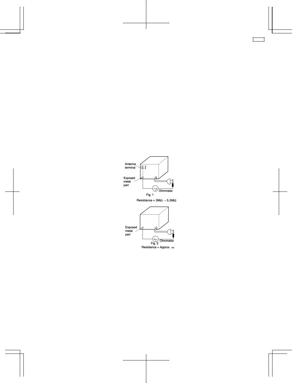
1.1.Insulation Resistance Test
1.Unplug the power cord and short the two prongs of the plug with a jumper wire.
2.Turn on the power switch.
3.Measure the resistance value with ohmmeter between the jumper AC plug and each exposed metal cabinet part, such as screwheads, antenna, control shafts, handle brackets, etc.
Equipment with antenna terminals should read between 3 MΩ and 5.2 MΩ to all exposed parts*.(Fig.1) Equipment without antenna terminals should read approximately infinity to all exposed parts.(Fig.2) *Note: Some exposed parts may be isolated from the chassis by design. These will read infinity.
4.If the measurement is outside the specified limits, there is a possibility of a shock hazard. The equipment should be repaired and rechecked before it is returned to the customer.
3
SA-AK22
2 Before Repair and Adjustment
Disconnect AC power, discharge Power Supply Capacitors C536, C545 and C546 through a 10Ω, 5W resistor to ground. DO NOT SHORT-CIRCUIT DIRECTLY (with a screwdriver blade, for instance), as this may destroy solid state devices. After repairs are completed, restore power gradually using a variac, to avoid overcurrent.
Current consumption at AC 120V, 60 Hz in NO SIGNAL mode should be ~400mA.
3 Protection Circuitry
The protection circuitry may have operated if either of the following conditions are noticed:
∙No sound is heard when the power is turned on.
∙Sound stops during a performance.
The function of this circuitry is to prevent circuitry damage if, for example, the positive and negative speaker connection wires are “shorted”, or if speaker systems with an impedance less than the indicated rated impedance of the amplifier are used.
If this occurs, follow the procedure outlines below:
1.Turn off the power.
2.Determine the cause of the problem and correct it.
3.Turn on the power once again after one minute.
Note :
When the protection circuitry functions, the unit will not operate unless the power is first turned off and then on again.
4 Accessories
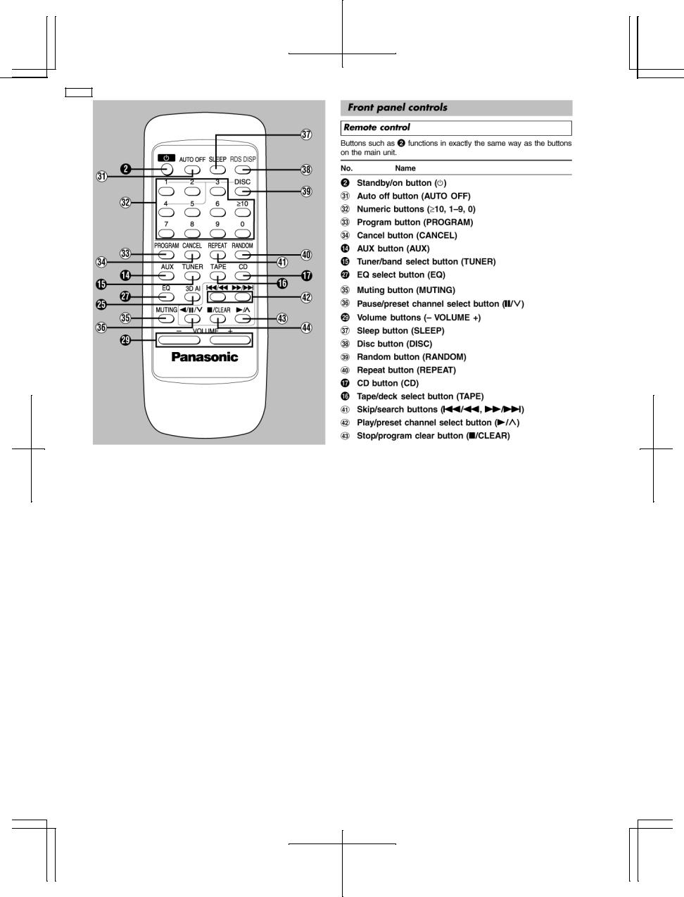
Remote Control
Transmitter
FM indoor antenna
AC mains lead
AM Loop antenna
4
SA-AK22
5 Handling Precautions For Traverse Deck
The laser diode in the traverse deck (optical pickup) may break down due to potential difference caused by static electricity of clothes or human body.
So, be careful of electrostatic breakdown during repair of the traverse deck (optical pickup).
∙ Handling of traverse deck (optical pickup)
1.Do not subject the traverse deck (optical pickup) to static electricity as it is extremely sensitive to electrical shock.
2.The short land between the No.4(LD) and No.5(GND) pins on the flexible board (FFC) is shorted with a solder build-up to prevent damage to the laser diode.To connect to the PC board, be sure to open by removing the solder build-up, and finish the work quickly.
3.Take care not to apply excessive stress to the flexible board (FFC).
4.Do not turn the variable resistor (laser power adjustment). It has already been adjusted.
∙Grounding for electrostatic breakdown prevention
1.Human body grounding
Use the anti-static wrist strap to discharge the static electricity from your body.
2.Work table grounding
Put a conductive material (sheet) or steel sheet on the area where the traverse deck (optical pickup) is placed, and ground the sheet.
Caution :
The static electricity of your clothes will not be grounded through the wrist strap. So, take care not to let your clothes touch the traverse deck (optical pickup).
Caution when Replacing the Traverse Deck :
The traverse deck has a short point shorted with solder to protect the laer diode against electroststics breakdown. Be sure to remove the solder from the short point before making connections.
5

SA-AK22
6 Precaution of Laser Diode
CAUTION:
This unit utilizes a class 1 laser.
Invisible laser radiation is emitted from the optical pickup lens.
When the unit is turned on:
1.Do not look directly into the pick up lens.
2.Do not use optical instruments to look at the pick up lens.
3.Do not adjust the preset variable resistor on the pickup lens.
4.Do not disassemble the optical pick up unit.
5.If the optical pick up is replaced, use the manufacturer’s specified replacement pick up only.
6.Use of control or adjustments or performance of procedures other than those specified herein may result in hazardous radiation exposure.
CAUTION!
THIS PRODUCT UTILIZES A LASER.
USE OF CONTROLS OR ADJUSTMENTS OR PERFORMANCE OF PROCEDURES OTHER THAN THOSE SPECIFIED HEREIN MAY RESULT IN HAZARDOUS RADIATION EXPOSURE.
6

SA-AK22
7 Operation Procedures
7
SA-AK22
8
SA-AK22
8Operation Checks and Main Component Replacement Procedures
“ATTENTION SERVICER”
Some chassis components may have sharp edges.
Be careful when disassembling and servicing.
1.This section describes procedures for checking the operation of the major printed circuit boards and replacing the main components.
2.For reassembly after operation checks or replacement, reverse the respective procedures. Special reassembly procedures are described only when required.
3.Select items from the following index when checks or replacement are required.
Contents
∙Disassembly and assembly main unit
1.Checking of the Main, Panel, Deck and Power P.C.B.
∙Main Component Replacement Procedures
1.Replacement of the Traverse Deck.
2.Replacement of the Power Amplifier IC.
∙Disassembly and assembly of the Traverse Unit
∙Disassembly and assembly of the Disc Tray Warning:
This product uses a laser diode. Refer to caution statement Precaution of Laser Diode.
9
SA-AK22
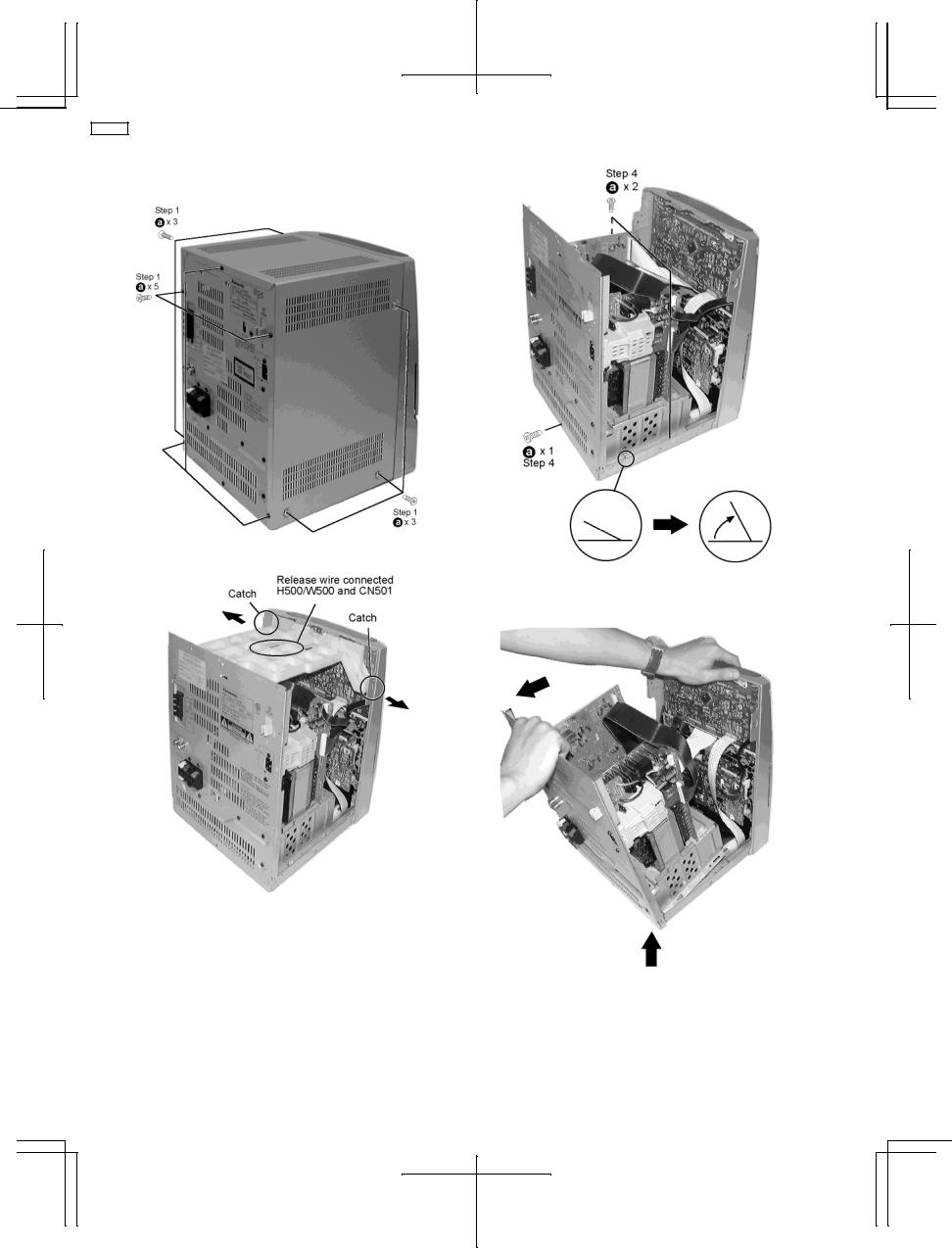
8.1.Disassembly and assembly main unit
Step 1 Remove 3 screws each side and 5 screws at rear panel.
Step 2 Remove the Top Cabinet
Step 3 Remove T-bracket.
Step 4 Remove 2 screws each side of the inner chassis and a screw at the rear panel. Turn locating pin 90°.
(Locating pin need not have to be bent back).
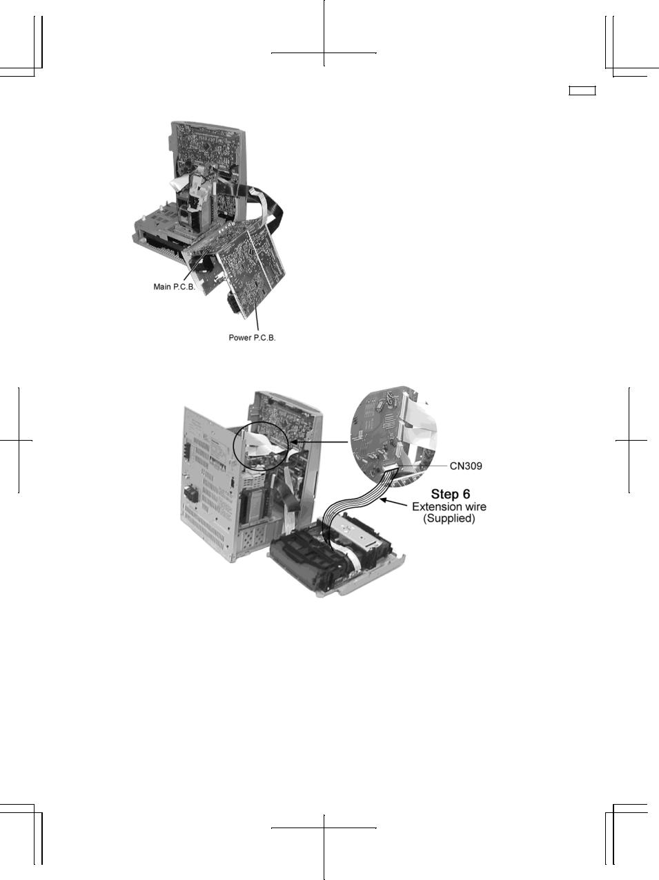
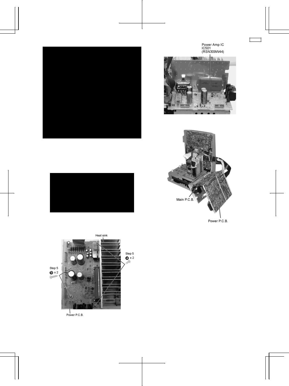
Step 5 Release the wires CN 300, 301, 302, 304 and 309.
Remove rear panel by pulling backward and lift rear panel assy off.
10
SA-AK22
Remove Front Panel
Step 4 : Remove the CD lid in the direction of the arrow.
Step 5 : Release the two catches shown above to remove the front cabinet from the CD Traverse Unit.
Step 1 : Use a hexagonal wrench and turn clockwise to release the tray.
Step 2 : Remove the 2 screws.
Separated front and rear panel assy.
Step 3 : Push the CD tray in the direction shown above.
11
SA-AK22
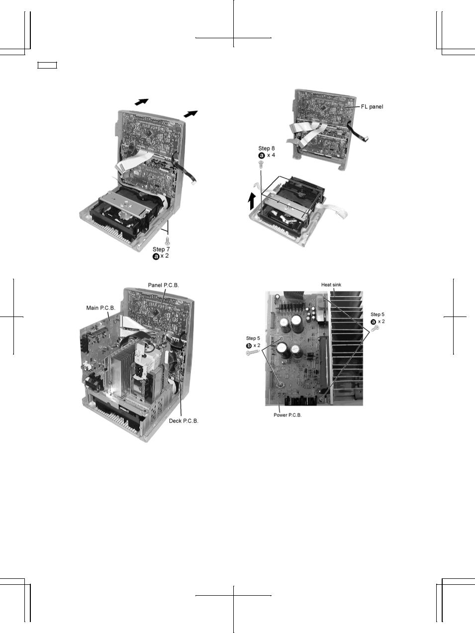
Step 7 Remove 2 screws from bottom and 2 screw beside inner bracket to push forward to release the front panel.
Removal of Inner bracket.
Step 8 To release inner bracket, remove 4 screws.
8.1.1.Checking for Panel, Main and Deck P.C.B.
Step 1 Remove 2 screws each side.
12
SA-AK22
8.1.2.Checking for Power P.C.B.
8.1.3.For Live Troubleshooting Procedure
Step 6 : Reconnect all connectors.
Step 7 : Use extension 14pin FFC wire for CN309.
Step 8 : Supply power for troubleshooting.
13
SA-AK22
8.2.Main Component Replacement Procedures
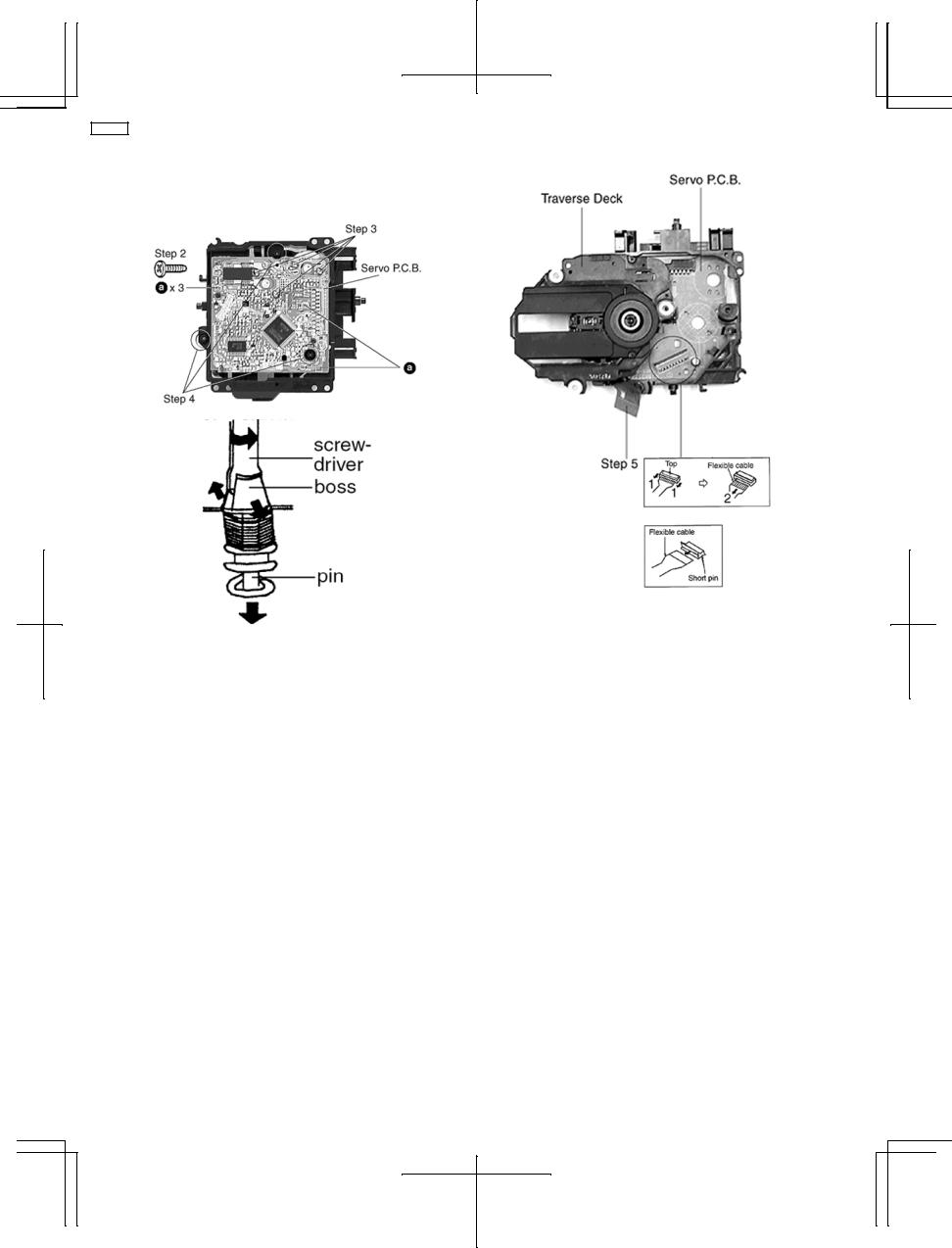
1. Replacement of the Traverse Deck
Step 1 Follow the procedures in ‘Disassembly of the Traverse
Unit’ ( Step 1 - Step 4 )
Step 3 Desolder the 4 legs of the 2 motors and pull out the Servo P.C.B.
Step 4 Widen the 3 bosses with a flat screwdriver and pull out the 3 pins. Then remove the Traverse Deck.
Step 5 Remove the flexible cable CN 701.
∙Removal of the flexible cable. Push the top of the connector in the direction of the arrow 1, and then pull out the flexible cable in the direction of the arrow 2.
Note:
Insert a short pin into the flexible cable for traverse unit.
∙ Installation of the CD servo P.C.B. after replacement
Step 1 Connect the FFC board.
Step 2 Install the CD servo P.C.B. in the traverse deck assembly.
14
SA-AK22
Step6 Unsolder the terminals of Power Amp IC and replace the respective component.
Note:
Before installing the CD servo P.C.B., move the optical pickup towards the outer edge from the marking (black triangle). [Otherwise, the reset detect switch (S701) mounted on the CD servo P.C.B. may be damaged.]
2. Replacement of the Power Amplifier IC
Step 1 Follow the procedures in ‘Checking Procedure for each major P.C.B.’ ( Step 1 - Step 6 ).
Step 4 Remove the wires at CN302, CN303 and CN304 and pull out the Main P.C.B.
Step 5 Remove 4 screws fixed to the Power Amplifier IC.
15
SA-AK22
8.3.Disassembly and assembly of the Traverse Unit
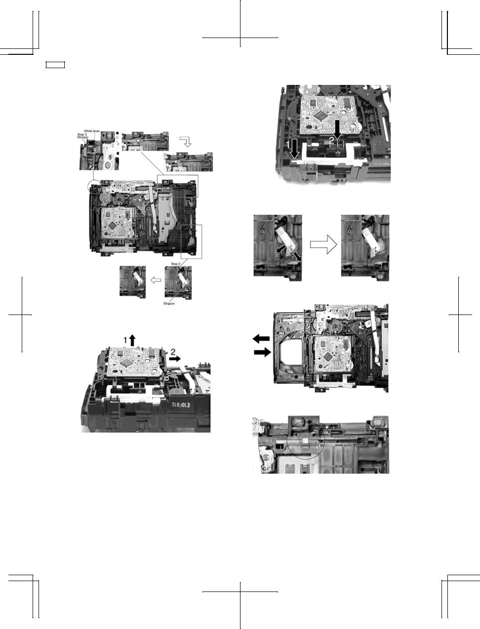
Step 1 Push the lever from position A to B.
Step 2 Pull the stopper (black) in the direction of arrow 1 and push the lever in the direction of arrow 2.
Step 3 Push the stpeer (black) down until the white lever eject out.
Step 4 Lift up the traverse unit and slide out the unit as shown.
∙ Replacement of Traverse Unit
Step 1 Place the traverse unit as shown.
Step 2 Press in the lever shaft in the direction of arrow 1 as shown and push the traverse unit into the position in the direction of arrow 2.
Step 3 Pull the stopper in the direction of arrow 1 and release the lever in the direction of arrow 2 as shown.
Step 4 Pull out the tray half way and push it back fully.
Step 5 Push the lever to the initial position indicated ‘I---I’.
16

SA-AK22
8.4.Disassembly and assembly of the Disc Tray
Step 5 Rotate the hexagonal wrench in the direction of arrow (clockwise), and then open the disc tray fully.
Step 2 With lifting the claw in the direction of arrow 1, draw the clamp SW P.C.B. in the direction of arrow 2.
Step 3 Remove the mechanism cover.
Step 6 Upset the CD changer unit again.
Step 7 Release both the claws, and then draw the disc tray.
Step 4 Insert the gear with hexagonal wrench into the hole.
Step 8 With forcing the left guide bar manually because the left guide bar interfers with claw, draw the disc tray.
∙ Installation of the disc tray after replacement
17

SA-AK22
Step 1 Slide the drive rack fully in the direction of arrow.
Step 2 Holding the drive rack not to move, install the disc tray.
Step 3 Align the drive rack with the driver gear.
Step 4 Holding the disc tray manually, rotate the pulley gear in the direction of arrow.
Step 5 Rotate the gear 5 or 6 times manually, and then push the disc tray.
18
SA-AK22
9 Self-Diagnostic Function
9.1.Self-diagnostic display
This unit is equipped with a self-diagnostic display function which, if a problem occurs, will display an error code corresponding to the problem.
Use this function when performing maintenance on the unit.
9.2.How to enter the Self-Diagnostic Function
9.3.Cassette Mechanism Test (For error code H01, H02, H03, F01, F02)
1.Press “TAPE, DECK 1/2” to select Deck 2.
2.Load a cassette tape with the erasure prevention tab, remove from left side only and close the cassette holder.
3.Press “FAST FORWARD MEMORY” (Tape will be stop after 2 seconds)
4.Load a cassette tape with the erasure prevention tab, remove from right side only and close the cassette holder.
5.Press “REVERSE FM MODE/BP” (Tape will be stop after 2 seconds)
6.Load a pre-recorded tape with both side record tabs intact and close the cassette holder.
7.Press “PLAY/TUNE/TIME ADJ UP” (After TPS function, tape will stop automatically)
8.Press “REC/STOP” (Tape will not move)
9.Press “STOP/TUNE MODE” to indicate Error code.
∙If several problem exist, error code will change each time when “■ /TUNE MODE” is pressed. (e.g. H01 → H03 → F01 .....etc.)
10.Press “TAPE, DECK 1/2” to select Deck 1.
11.Repeat step 2 to 9 to test Deck 1. (Tape Deck 1 will not check H02 because of no recording function)
19
SA-AK22
9.4.CD Mechanism Test (F15, F26, F16, F17, F27, F28, F29, H15)
1.Press “CD”.
2.Press “OPEN/CLOSE (1)” and place a CD.
3.Press “OPEN/CLOSE (1)” to close the tray.
4.Press “OPEN/CLOSE (5)” and wait until the tray is open.
5.Press “OPEN/CLOSE (1)” and remove the CD.
6.Press “OPEN/CLOSE (1)” to close the tray.
7.Press “■/TUNE MODE” to indicate Error Code.
∙If several problem exist, error code will change each time when “■/TUNE MODE” is pressed. (e.g. F15 → F26 → F16 ....etc).
9.5.To clear all Error code
1.Press “STOP/TUNE MODE” button for 5 seconds.
2.FL indicator shows “CLEAR” for 1 second and change to “T”.
9.6.How to get out from Self-Diagnostic function
1. Press “Power” button OFF.
9.7.Power Amplifier Failure (F61)
1. When power amplifier fail, F61 will indicate automatically.
10 Description of Error Code
10.1. Error detection for Cassette Mechanism block
No. |
Error |
Error |
Problem condition |
|
|
Display |
|
1 |
MODE SW |
H01 |
Faulty operation of cassette mechanism. |
|
detection error |
|
Faulty contact or short-circuit of mechanism mode switch (S951, S971). |
|
|
|
|
2 |
REC INH SW |
H02 |
Recording not possible. |
|
detection error |
|
Faulty contact or short-circuit of REC INH switch (S974, S975). |
|
|
|
|
3 |
HALF SW |
H03 |
Playback cannot perform. |
|
detection error |
|
Faulty contact or short-circuit of HALF siwtch (S952, S972). |
4 |
Reel Pulse |
F01 |
The tape advances slightly and then stops. |
|
detection error |
|
Faulty reel pulse, faulty hole detect IC (IC951, IC971). |
|
|
|
|
5 |
TPS abnormal |
F02 |
Cassette deck will not perform TPS function. |
|
|
|
Faulty playback EQ/recording amplifier IC (IC101). |
|
|
|
|
10.2. Error detection for CD/Changer block
No. |
Error |
Error |
Problem condition |
|
|
Display |
|
|
|
|
|
1 |
REST SW detection error |
F15 |
CD does not function. |
|
|
|
This error occurs when the Optical Pick Up REST SW (S701) is not |
|
|
|
detected within the specified time (about 8 seconds) |
2 |
CD tray opens automatically |
F16 |
CLAMP switch (S4) NG (Check & Replace) |
|
|
|
|
3 |
Does not startup when [PLAY] |
F17 |
BOTTOM switch (S5) NG (Check & Replace) |
|
button is pressed |
|
|
|
|
|
|
4 |
Transmission error between CD |
F26 |
CD does not function. |
|
servo LSI and micon |
|
This error occurs when the POWER is ON for the CD block and an error |
|
|
|
is |
|
|
|
detected after the transmission has started. |
5 |
Startup fails even when you |
F27 |
Tray 1 detect switch or Tray 2 detect switch NG (Check & Replace) |
|
insert CD or the selected disc tray |
|
|
|
does not open |
|
|
|
|
|
|
6 |
Cannot insert CD |
F28 |
Tray 1 detect switch NG (Check & Replace) |
|
|
|
|
7 |
Cannot eject CD |
F29 |
Check if disc is stuck. Tray 2 detect switch NG (Confirm & Replace) |
8 |
The CD tray closes |
H15 |
CD disc tray detect switch NG (S3) (Check & Replace) |
|
|
|
|
20
SA-AK22
10.3. Power Supply related error detection
No. |
Error |
Error |
Problem condition |
|
|
Display |
|
|
|
|
|
1 |
POWER AMP |
F61 |
When POWER is switched on, power become off automatically. |
|
output abnormal |
|
During normal operation, if DC DET become L, PCNT shall become |
|
|
|
L and the error display on the left shall be displayed. (IC501) |
|
|
|
|
11 CD Test Mode Function
This CD test mode is provided to check CD unit without connecting to changer loading mechanism. This mode shall operate CD PLAY with CD unit being connected only and CD Automatic Alignment result is shown on FL display.
11.1. How to set CD test mode
11.2. CD Automatically Adjustment result indication
Under CD test mode, pressing the numeric key ‘0’ on the remote controller will display the auto adjustment result. FLOCK, TLOCK and CLVS status shall be shown as below:
During the above display, executing CD PLAY will display auto adjustment result for CD PLAY mode.
12 Measurements and Adjustments
12.1. Cassette Deck Section
∙Measurement Condition
−Tape edit: NORMAL
−Record timer: OFF
−Make sure head, capstan and press roller are clean.
−Judgeable room temperature 20 ± 5 °C (68 ± 9°F)
∙Measuring instrument
−EVM (Electronic Volmeter)
−Digital quency counter
∙Test Tape
−Tape speed gain adjustment (3 kHz, -10 dB); QZZCWAT
12.1.1. Tape Speed Adjustment (Deck 1/2)
1.Set the tape edit button to “NORMAL” position.
2.Insert the test tape (QZZCWAT) to DECK 2 and playback (FWD side) the middle portion of it.
3.Adjust Motor VR (DECK 2) for the output value shown below.

 Adjustment target: 2940 ~ 3060 Hz (NORMAL speed)

21

SA-AK22
4.After alignment, assure that the output frequency of the DECK 1 FWD are within ±60 Hz of the value of the output frequency of DECK 2 FWD.
12.1.2. Bias and Erase Voltage Check
1.Set the unit “AUX” position.
2.Insert the Normal blank tape (QZZCRA) into DECK 2 and the unit to “REC” mode (use “ ● REC/STOP” key).
3.Measure and make sure that the output is within the standard value.
Bias voltage for Deck 2 |
14 ± 4mV (Normal) |
Standard value) |
|
Erase voltage for Deck 2 |
more than 80mV (Normal) |
12.1.3.Bias Frequency Adjustment (Deck 1/2)
1.Set the unit to “AUX” position.
2.Insert the Normal blank tape (QZZCRA) into DECK 2 and set the unit to “REC” mode (● use “REC/STOP” key).
3.Adjust L1002 so that the output frequency is within the standard value.

 Standard Value: 97 ±8 kHz

12.2. Tuner Section
12.2.1. AM-IF Alignment
∙ AM-IF ALIGNMENT
SIGNAL GENERATOR OR SWEEP |
|
RADIO DIAL SETTING |
INDICATOR |
ADJUSTMENT(Shown in |
REMARKS |
|
GENERATOR |
|
|
(ELECTRONIC |
Fig.3) |
|
|
|
|
|
|
VOLTMETER |
|
|
CONNECTIONS |
FREQUENCY |
|
|
|
|
|
|
|
|
|
OSCILLOSCOPE) |
|
|
Fashion a loop of |
450 kHz 30% Mod. |
Point of non- |
Headphone Jack (32Ω) |
Z102 (AM IFT) |
Adjust for maximum |
|
several turns of wire |
at 400Hz. |
|
interference (on/about |
Fabricate the plug as |
|
output. |
and radiate signal |
|
|
600 kHz) |
shown in Fig. 2 and then |
|
|
into loop of receiver. |
|
|
|
connect the lead wires of |
|
|
|
|
|
|
the plug to the |
|
|
|
|
|
|
measuring instrument. |
|
|
|
|
|
|
|
|
|
∙ FM/AM-RF ALIGNMENT
SIGNAL GENERATOR OR SWEEP |
RADIO DIAL SETTING |
INDICATOR |
ADJUSTMENT(Shown in |
REMARKS |
|
GENERATOR |
|
(ELECTRONIC |
Fig.1) |
|
|
|
|
|
VOLTMETER |
|
|
CONNECTIONS |
FREQUENCY |
|
|
|
|
|
|
|
OSCILLOSCOPE) |
|
|
Fashion a loop of |
520 kHz |
Tuning capacitor fully |
Headphone Jack (32Ω) |
Z101 (AM OSC Coil) |
Adjust for maximum |
several turns of |
|
closed. |
Fabricate the plug as |
|
output. |
wire and radiate |
|
|
shown in Fig. 2 and then |
|
|
signal into loop of |
|
|
connect the lead wires of |
|
|
receiver. |
|
|
the plug to the measuring |
|
|
|
|
|
instrument. |
|
|
|
|
|
|
|
|
Fashion a loop of |
600 kHz |
Tuning capacitor fully |
Headphone Jack (32Ω) |
Z101 (AM ANT Coil) |
Adjust for maximum |
several turns of |
|
open. |
Fabricate the plug as |
|
output. |
wire and radiate |
|
|
shown in Fig. 2 and then |
|
|
signal into loop of |
|
|
connect the lead wires of |
|
|
receiver. |
|
|
the plug to the measuring |
|
|
|
|
|
instrument. |
|
|
|
|
|
|
|
|
22
SA-AK22
12.3. Alignment Points
Cassette Deck Section
Tuner Section
23
SA-AK22
13 Illustration of IC’s, Transistors and Diodes
M38B79MFA053 (100P) |
BU2090AF-E2(16P) |
|
|
|
RSN3502C (14P) |
TA7291P |
M5218AP |
BH3874AKS2 (64P) |
|
|
|
|
|
93LC46B |
|
MN662790RSC (80P) |
LA1833NMNTLM(24P) |
|
|
|
|
||
|
|
|
|
|
|||
|
LC72131MDTRM(20P) |
|
|
|
|
|
|
|
AN7348STA-E1(24P) |
|
|
|
|
|
|
|
BA4558FE2(8P) |
|
|
|
|
|
|
|
AN8885SBE1(28P) |
|
|
|
|
1 |
|
|
|
|
|
|
|
|
|
|
|
|
|
|
|
10 |
|
BA7755A |
KTC2026 |
0N2180RLC1 |
AN8739SBE2 |
2SC2058SPTA |
2SK544F-AC |
||
KTA1046 |
2 |
|
|
|
|
|
|
|
|
|
|
|
|
||
|
|
1 |
|
|
|
|
|
|
|
2 |
4 |
3 |
|
|
|
|
|
3 |
|
|
|
||
|
|
1 |
|
4 |
|
|
|
2SD1859QRTV2 |
KRC114STA |
KTA12710YTA |
|
2SA1037AKSTX |
|
||
|
2SC2412KT96R |
|
|||||
|
|
KTD1146YTA |
|
|
|||
|
|
|
KRA102STA |
|
|||
|
|
2SB621ARSTA |
|
|
|||
|
|
|
KTC3875GRTA |
|
|||
|
|
KTC3205YTA |
|
|
|||
|
|
|
KRC111STA |
|
|||
|
|
KRC101MTA |
|
|
|||
|
|
|
KTD1304TA |
|
|||
|
|
KTC32030YTA |
|
|
|||
|
|
|
KRC102STA |
|
|||
|
|
|
|
|
|
|
|
|
|
|
|
|
|
KRA102STA |
|
2SA933SSTA |
|
KRA102MTA |
DAP202KT146 |
|
|
||
|
KRC103MTA |
|
MA8300MTX |
|
|||
2SC2787FL1TA |
|
|
|
||||
|
KRC102MTA |
|
1SS355TE17 |
|
|||
2SD2144STA |
|
|
|
||||
|
KRA110MTA |
|
UDZSTE175R1B |
|
|||
KTC3199GRTA |
|
|
|
||||
|
|
|
|
|
UDZSTE177R5B |
|
|
RVTDTC143EST |
|
|
|
|
|
|
|
|
|
|
|
|
UDZTE173R6B |
|
|
2SC2786MTA |
|
|
|
|
|
|
|
|
|
|
|
|
UDZSTE179R1B |
|
|
|
|
BC E |
|
|
|
|
|
|
|
|
|
|
|
|
|
RL1N4003S-P |
SVC211SPA-AL |
SLI325URCT31 |
|
|
GP1S94 |
||
1N5402BM21 |
|
SLR325MCT31W |
MA4020LTA |
|
|||
|
|
|
|||||
1T3T |
|
|
|
|
|
|
|
|
|
|
|
MTZJ6R8BTA |
|
|
|
|
|
|
|
|
|
|
|
|
|
|
|
|
MTZJ4R7BTA |
|
|
|
|
|
|
|
MTZJ10BTA |
|
|
|
|
|
|
|
MTZJ15CTA |
|
|
|
|
|
|
|
MTZ556BTA |
|
|
RVD1SS133TA |
|
1SS355TE17 |
|
|
|
||
|
|
|
|
|
|
|
|
1SS291TA |
|
|
|
|
|
|
|
MA165TA |
|
|
|
|
|
|
|
MA700ATA |
|
|
|
|
|
|
|
MA723TA |
|
|
|
|
|
|
|
24
 Loading...