


GA-AS10TPoE+ Series
Table of contents
 Loading...
Panasonic GA-AS10TPoE+ Series, GA-AS10T Series, GA-AS12T Series, GA-AS4T Series, GA-AS4TPoE+ Series Instruction Manual
...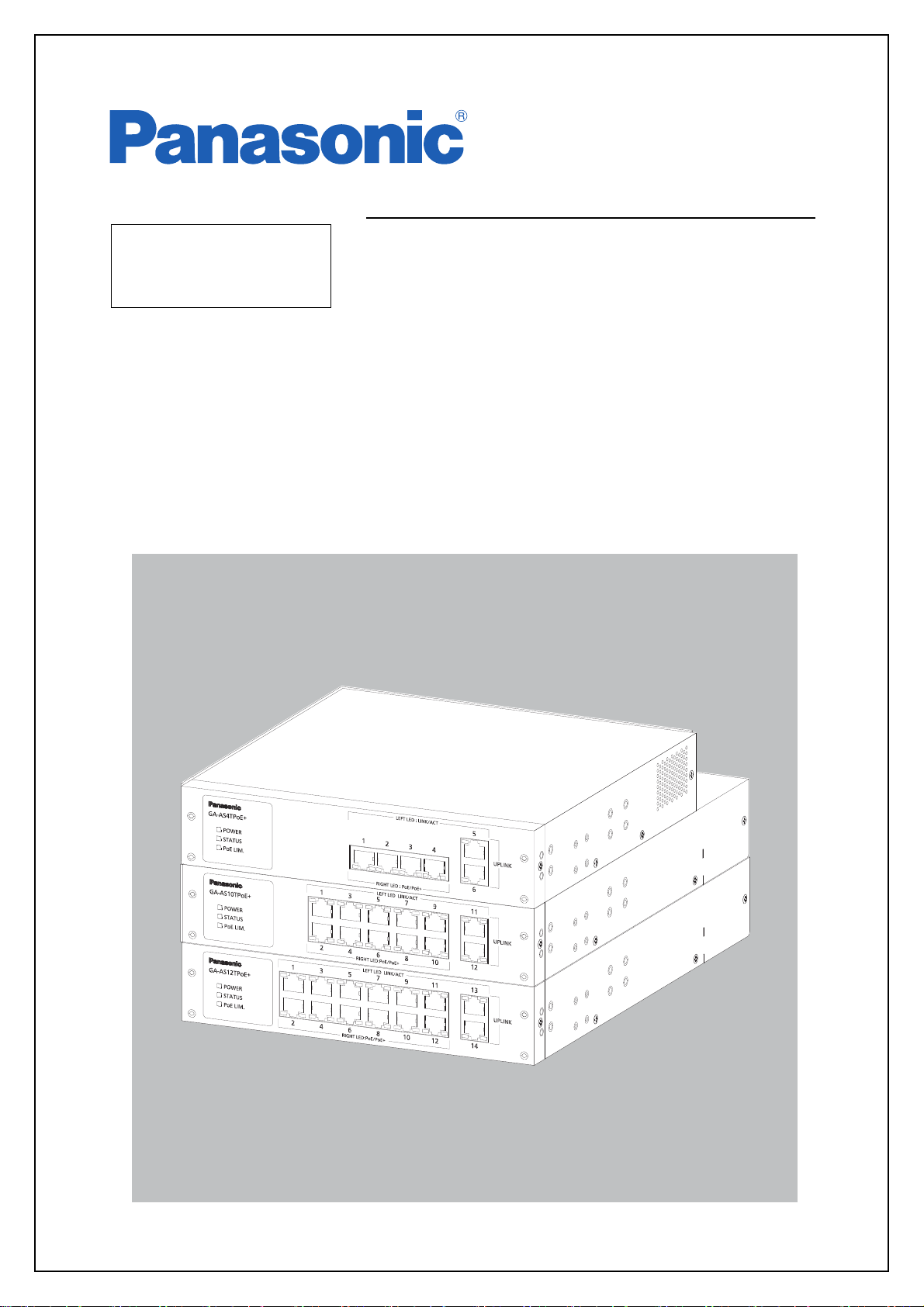
Layer 2 Switching Hub
Instruction
Manual
Model No. PN25041/PN25048
PN25101/PN25108
PN25121/PN25128
Thank you for purchasing our product.
This manual provides important information about safe and proper operations
of this Switching Hub.
Please read 「Important Safety Instructions」 on pages 3 to 5 before use.
For target model names and numbers, refer to the next page.
Under all circumstances, customer disassembling of this Switching Hub voids the
warranty.

The target model for this Instruction Manual is as follows.
Model name Model number Firmware version
GA-AS4TPoE+
PN25048-ID
PN25048-TH
PN25048-MY
PN25048-SG
1.0.0.14 and above
GA-AS10TPoE+
PN25108-ID
PN25108-TH
PN25108-MY
PN25108-SG
1.0.0.14 and above
GA-AS12TPoE+
PN25128-ID
PN25128-TH
PN25128-MY
PN25128-SG
1.0.0.14 and above
GA-AS4T
PN25041-ID
PN25041-TH
PN25041-MY
PN25041-SG
1.0.0.07 and above
GA-AS10T
PN25101-ID
PN25101-TH
PN25101-MY
PN25101-SG
1.0.0.07 and above
GA-AS12T
PN25121-ID
PN25121-TH
PN25121-MY
PN25121-SG
1.0.0.07 and above
2

ヸモンワリワヨ
ヤモヶヵリヰワ
Important Safety Instructions
Please Follow the Instructions
ヸモンワリワヨ
This chapter contains important safety instructions for preventing bodily injury
and/or property damage. You are required to follow them.
■Severity of bodily injury and/or property
rect use of this Switching Hub, is explain
This symbol indicates a potential hazard that could result in serious
injury or death.
Deviation from these instructions could lead to bodily injury and/or
property damage.
■The following symbols are used to classify and describe the type of instructions
to be observed.
This symbol is used to alert users
to what they must not do.
● Do not use power other than AC 100-240 V.
Deviation could lead to fire, electric shock, and/or equipment failure.
damage, which could result from incor-
ed below.
This symbol is used to alert users
to what they must do.
● Do not handle this Switching Hub and connection cables during a
thunderstorm.
Deviation could lead to electric shock.
● Do not disassemble and/or modify this Switching Hub.
Deviation could lead to fire, electric shock, and/or equipment failure.
● Do not damage the power cord. Do not bend too tightly, stretch,
twist, bundle with other cord, pinch, put under a heavy object, and/
or heat it.
A damaged power cord could lead to fire and/or electric shock.
● Do not handle the power cord with wet hands.
Deviation could lead to electric shock and/or equipment failure.
● Do not put foreign objects (such as metal or combustibles) into the
opening and do not drop them inside the Switching Hub.
Deviation could lead to fire, electric shock, and/or equipment failure.
3
● Do not store and/or use this Switching Hub at a location where liq-
ヸモンワリワヨ
ヤモヶヵリヰワ
ヤモヶヵリヰワ
uid (water) may be spilled, or hi
sive gas, flammable gas is present.
Deviation could lead to fire, electric shock, and/or equipment failure.
● Do not store and/or use this Switching Hub under direct sunlight
and/or high temperature.
Deviation could lead to high internal temperature and cause fire.
● Do not store and/or use this Switching Hub at a location with continuous vibration or strong shock, or at an unstable location.
The Switching Hub may fall causing injury and/or equipment failure.
● Do not put this Switching Hub into fire.
Deviation could lead to explosion and/or fire.
gh humidity, conductive dust, corro-
● Do not connect devices other than 10BASE-T/100BASE-TX/
1000BASE-T to a twisted pair port.
Deviation could lead to equipment failure.
● Use the bundled power cord (AC 100-240 V specifications).
Deviation could lead to electric shock, malfunction, and/or equip-
ment failure.
● Unplug the power cord in case of equipment failure.
Leaving failed equipment connected for a long time could lead to fire.
● Be sure to connect this Switching Hub to ground.
Deviation could lead to electric shock, malfunction, and/or equip-
ment failure.
Connect the supplied power cord into the grounded electric outlet.
If the electric outlet is not grounded, connect the grounding line
(AWG18: green/yellow) to the ground terminal screw.
● Connect the power plug firmly to the power port.
Deviation could lead to electric shock or malfunction.
4

● Unplug the power cord if the STATUS LED flashes in orange. This
ヤモヶヵリヰワ
shows failure.
Leaving failed equipment connected for a long time could lead to fire.
● Handle the Switching Hub carefully so that fingers or hands may
not be damaged by the twisted pair port or power cord hook block.
●To connect a power receiving equipment supporting IEEE802.3at
to this Switching Hub, use a cable rated Cat5e or higher.
Using other cables may result in heat generation, ignition, and/or
equipment failure.
● When installing this Switching Hub on a wall, use the separately
sold mounting bracket PN71053 (wall-mount bracket). Securely
mount and install the Switching Hub so it would not fall under its
own weight or the weight of connection cables.
The Switching Hub may fall causing injury and/or equipment failure.
● Up to two Switching Hubs can be connected side by side. For this,
use the connecting brackets and screws (for attaching the connecting bracket) included in the separately sold mounting bracket
PN71052 (for 19-inch rack mount, for two Switching Hubs).
Securely attach the connecting brackets to the connecting screw
holes on the front and back panels, and then install the Switching
Hubs.
If the Switching Hubs are not securely fixed, they may fall causing
injury and/or equipment failure.
● Perform maintenance at periodic intervals to maintain performance.
Assign an administrator for this product and make sure to perform
periodic maintenance. Refer to Panasonic Eco Solutions Network's
web site for the inspection table that lists all required items to be
checked during maintenance.
● When designing a system using this Switching Hub, place appropriate measures such as setting it up in a redundant configuration.
Communication failure may occur due to failure and/or malfunction
of the equipment during use.
5
● When using this Switching Hub for a purpose that requires
ヤモヶヵリヰワ
Important Notice for Measures against Failures Caused
by Lightning Strikes
● When connecting devices (especially outdoor devices) prone to lightning
strikes, such as network cameras or wireless access points, to a twisted pair
port of this Switching Hub, overcurrent and/or overvoltage caused by lightning passing through the twisted pair cable may affect this Switching Hub,
causing equipment failure. When connecting such devices, we strongly recommend installing a lightning arrester (SPD: Surge Protective Device) at the
twisted pair port side of the Switching Hub.
● Overcurrent and/or overvoltage caused by lightning may affect this Switching
Hub through a power source connected to the power port and/or a grounding line, causing equipment failure. When there is a possibility of overcurrent/
overvoltage from lightning affecting this Switching Hub from a power source
and/or a grounding line, we strongly recommend installing a lightning
arrester (SPD: Surge Protective Device) at the power port side of the Switching Hub.
● In case this Switching Hub fails due to lightning strikes, repair charges will
apply even during the warranty period as prescribed in the free repair provisions on page 19 of the Operation Manual (print) which is included to each
device.
extremely high reliability, take all possible measures to ensure
safety and reliability.
This Switching Hub is not designed and/or manufactured with the
intent of being used for applications that require extremely high reli-
ability (application in the railways, aviation, medical areas in which
adverse effects caused by communication failure or those that
directly affect human life must be avoided).
● Pay attention to any failure caused by the usage environment
including aging degradation.
The performance of this Switching Hub may drop due to aging degra-
dation of parts, etc. depending on various conditions including the
rate of operation or usage environment. It is recommended to
replace this Switching Hub approximately five years after installment.
6

Basic Instructions for the Use of This Product
● For internal inspection and/or repair, please contact your dealer.
● Use commercial power supply from a wall socket, which is close and easily
accessible from this Switching Hub.
● Unplug the power cord when installing or moving this Switching Hub.
● Unplug the power cord when cleaning this Switching Hub.
● Use this Switching Hub within the specifications. Deviation could lead to malfunctions.
● When mounting with magnets, be sure to confirm that this Switching Hub
does not move or fall under the weight of the cables. Connect cables while
holding the Switching Hub down.
● Do not touch the metal terminal of the RJ45 connector (twisted pair port) or
metal terminal of the modular plug of connected twisted pair cable. Do not
place charged objects in the proximity of them.
Static electricity could lead to equipment failure.
● Do not put the modular plug of the connected twisted pair cable on or near
an object that can carry static electricity, such as a carpet. Static electricity
could lead to equipment failure.
● Do not apply strong shock, including dropping, to this Switching Hub. Deviation could lead to equipment failure.
● Please use this Switching Hub in places where the ambient temperature is in
the range from 0 to 50 degrees C.
Do not store and/or use this Switching Hub in an environment with any of
the characteristics listed below.
(Store and use this Switching Hub in an environment in accordance with the
specifications.)
― High humidity. Possible spilled liquid (water).
― Dusty. Possible static charge (such as on a carpet).
― Under direct sunlight.
― Possible condensation. High/low temperature exceeding the environment
specifications.
― Strong vibration and/or strong shock.
Failure to satisfy the conditions above may result in a fire, electric shock, equip-
ment failure, and/or malfunction. Such events are not covered by the warranty.
7

● Do not cover vent holes of this Switching Hub.
Covering vent holes could lead to rise of internal temperature and eventual
equipment malfunction.
● Do not stack Switching Hubs. When placing the Switching Hubs side by side,
ensure clearance of 20 mm or more.
● When mounting the Switching Hub in a rack, ensure clearance of 20 mm or
more between upper or lower device.
1. Panasonic will not be liable for any damage (including but not limited to loss of
profits, loss of opportunity, etc.) resulting from the operation not in accordance
with this operation manual, which may or may not be caused by failure and/or
malfunction of this device.
2. The contents described in this document may be changed without prior notice.
3. For any questions, please contact your dealer.
8

Table of Contents
Important Safety Instructions ............................................................................ 3
● Basic Instructions for the Use of This Product .................................................. 7
1. Product Outline ........................................................................................ 11
1.1. Features ............................................................................................... 11
1.2. Accessories .......................................................................................... 12
1.3. Optional Parts ...................................................................................... 13
1.4. Part Names and Functions .................................................................... 14
1.5. LED Behavior ........................................................................................ 15
1.5.1.LED Behavior during Start-up ........................................................... 15
1.5.2.LED Behavior while Operating ......................................................... 16
1.5.3.Operation Overview of PoE Power Supply Function on PoE Supported
Models 18
2. Installation ............................................................................................... 19
3. Connection .............................................................................................. 20
3.1. Connecting a Twisted Pair Port ............................................................. 20
3.2. Connecting to Power ........................................................................... 21
4. Web Browser-based Control ..................................................................... 22
4.1. Operating Environment ........................................................................ 22
4.2. IP Address Configuration ...................................................................... 23
4.3. Access to Web Control Function ........................................................... 24
4.4. Displaying Basic Information ................................................................. 27
5. Switch Configuration ............................................................................... 29
5.1. Basic Config ......................................................................................... 29
5.1.1.Administration Config ..................................................................... 29
5.1.2.IP Config ......................................................................................... 30
5.1.3.Basic Port Config ............................................................................. 31
5.1.4.Extend Port Config .......................................................................... 33
5.1.5.Power Saving Config ....................................................................... 34
5.1.6.System Security ............................................................................... 35
5.1.7.Syslog Transmission Config ............................................................. 36
5.1.8.ID/Password Change ....................................................................... 37
5.1.9.FDB Table ........................................................................................ 38
5.1.10.Time Config .................................................................................. 39
5.1.11.Static ARP Table ............................................................................ 40
5.1.12.ARP Table ..................................................................................... 41
5.2. Advanced Switch Configuration ........................................................... 42
5.2.1.VLAN Management ........................................................................ 42
5.2.1.a. VLAN Modification ............................................................... 44
5.2.2.VLAN Creation ................................................................................ 45
5.2.3.VLAN Port Config ............................................................................ 46
9

5.2.4.Traffic Class Config .......................................................................... 47
5.2.5.Diffserv Config ................................................................................ 48
5.2.6.Link Aggregation Config ................................................................. 49
5.2.6.a. Link Aggregation Modification ............................................. 50
5.2.7.Storm Control Config ...................................................................... 51
5.2.8.Port Monitoring Config ................................................................... 52
5.2.9.Static Multicast Address Config ....................................................... 54
5.2.10.PoE Port Config (for PoE Supported Models) ................................. 55
5.2.11.PoE Global Config (for PoE Supported Models) .............................. 57
5.2.12.Port Group Config ......................................................................... 58
5.3. System Tools ........................................................................................ 59
5.3.1.Software Update ............................................................................. 59
5.3.2.Reboot ............................................................................................ 60
5.3.3.Save Current Config ........................................................................ 61
5.3.4.Statistics .......................................................................................... 62
5.3.5.System Log ..................................................................................... 65
5.3.5.a. System Log Config ............................................................... 67
5.3.6.Config File Transfer ......................................................................... 68
5.3.7.Ping Execution ................................................................................ 69
5.3.8.Exception Handler ........................................................................... 70
5.3.9.Watchdog Timer ............................................................................. 71
6.Appendix ...................................................................................................... 72
6.1. Specifications ....................................................................................... 72
6.2. Easy IP Address Setup Function ............................................................ 74
7.Troubleshooting ............................................................................................ 75
8.After-sales Service ......................................................................................... 77
10

1. Product Outline
GA-AS4TPoE+/GA-AS10TPoE+/GA-AS12TPoE+/GA-AS4T/GA-AS10T/GA-AS12T
are Ethernet Switching Hubs that feature the Web control function and 10/100/
1000BASE-T ports.
The downlink ports support the PoE power supply function for IEEE802.3at/af
compatible devices.
1.1. Features
・ All ports (twisted pair ports) are 10/100/1000BASE-T ports that support auto-
negotiation.
Speed and communication mode can be switched by configuring the settings.
・ The downlink ports of PoE supported models can provide PoE power supply to
IEEE802.3at and IEEE802.3af compatible devices.
A single port can supply power by PoE up to 30 W.
The total number of ports, number of downlink ports, and amount of power
supply by the whole unit are shown below for each model.
Number of downlink
Model name Total number of ports
GA-AS4TPoE+ 6 (port 1 to 6) 4 (port 1 to 4) 62 W
GA-AS10TPoE+ 12 (port 1 to 12) 10 (port 1 to 10) 70 W
GA-AS12TPoE+ 14 (port 1 to 14) 12 (port 1 to 12) 84 W
(PoE power supply
ports
supported)
Power supply by the
whole unit
・ All twisted pair ports support the straight/cross cable auto sensing function.
You can simply connect devices with a straight cable, whether the target is a ter-
minal or a network device.
(By factory default, downlink ports are fixed to MDI-X.)
・ The IEEE802.3az (LPI) compatible Energy Efficient Ethernet (EEE) function is sup-
ported, allowing reduction of power consumption of each port by automatically
switching to a power saving state when there is no data communication at link
up.
・ The power saving mode detects the connection status automatically, and
reduces power consumption to a minimum.
・ The IEEE802.1Q compatible tag VLAN is supported, allowing registration of up
to 256 VLANs.
・ The Internet Mansion function is supported, allowing to ensure security of each
room in a building.
・ The IEEE802.1p compatible QoS function is supported.
・ The IEEE802.3ad compatible link aggregation function is supported, allowing
aggregation up to 8 ports.
(For GA-AS4TPoE+ and GA-AS4T, up to 6 ports.)
11

1.2. Accessories
Please be sure to confirm the contents. Please contact your dealer if any item is
missing.
・Switch 1
・Operation Manual 1
・ CD-ROM (including Operation Manual (this manual), ZEQUO assist Plus) 1
・Rubber foot 4
・Power cord 1
12

1.3. Optional Parts
・ PN71051 19-inch rack mount bracket (for one unit)
・ PN71052 19-inch rack mount bracket (for connecting two units)
・ PN71053 Wall-mount bracket
13
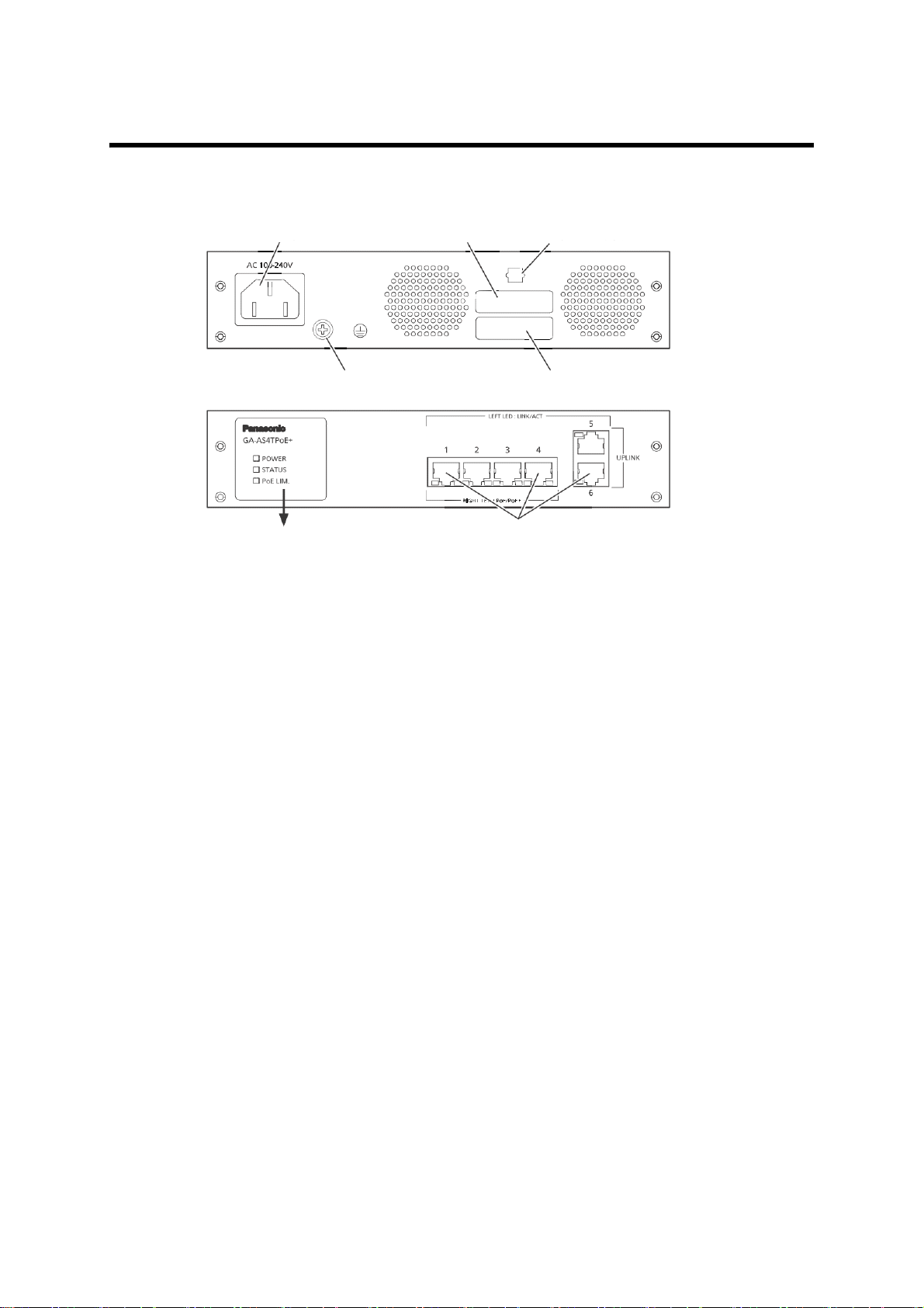
1.4. Part Names and Functions
Back
Front
See next page for
enlarged figure
10BASE-T/100BASE-TX/1000BASE-T
Ground terminal screw Manufacture number label
Power port MAC address label
Power cord hook block
Figure 1-1 External View (Example: GA-AS4TPoE+)
● Power port
Connect the supplied power cord into the port and connect the other end into
an electric outlet (AC 100-240 V).
● Power cord hook block
Hooking the supplied power cord on the block makes the cord less likely to be
unplugged from the power port.
●Ground terminal screw
If the electric outlet is not grounded, connect the grounding line (AWG18:
green/yellow) to the ground terminal screw.
● 10BASE-T/100BASE-TX/1000BASE-T ports (all ports)
10BASE-T/100BASE-TX/1000BASE-T compatible terminals, hubs, repeaters,
bridges, and switching hubs can be connected.
The length of the twisted pair cable (Cat5e or higher) connecting this switch
and a device must be 100 m or shorter.
● PoE power supply supported ports
(For GA-AS4TPoE+, GA-AS10TPoE+, and GA-AS12TPoE+; downlink ports)
Supports PoE power supply to IEEE802.3at/af compatible devices.
10BASE-T/100BASE-TX/1000BASE-T compatible terminals, hubs, repeaters,
bridges, and switching hubs can be connected.
The length of the twisted pair cable (Cat5e or higher) connecting this switch
and a device must be 100 m or shorter.
14

1.5. LED Behavior
1.5.1. LED Behavior during Start-up
When you turn on this switch, all LEDs are lit momentarily.
Then, self-diagnosis of the hardware is conducted. When the self-diagnosis is completed, the STATUS LED is lit in green, and the hardware starts operation as a
switching hub.
15
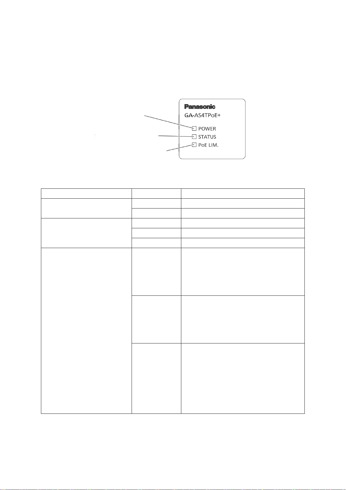
1.5.2. LED Behavior while Operating
POWER LED (Power)
STATUS LED (Status)
PoE LIM. LED (PoE limit)
Each switch has system LEDs and a set of LEDs for each port. These LEDs indicate
the operation status of the switch and each port.
・System LEDs
Figure 1-2 System LEDs (Example: GA-AS4TPoE+)
LED Behavior Description
POWER LED Green light Power On.
Off Power Off.
STATUS LED Green light System operating normally.
Orange light System starting-up.
Orange blink System failure.
PoE LIM. LED
(PoE supported models
only)
Off Supplies power 0 to 55 W.
[GA-AS4TPoE+]
Supplies power 0 to 63 W.
[GA-AS10TPoE+]
Supplies power 0 to 77 W.
[GA-AS12TPoE+]
Green light Supplies power 55 to 62 W.
[GA-AS4TPoE+]
Supplies power 63 to 70 W.
[GA-AS10TPoE+]
Supplies power 77 to 84 W.
[GA-AS12TPoE+]
Green blink When power supply by the whole
unit exceeds 62 W.
[GA-AS4TPoE+]
When power supply by the whole
unit exceeds 70 W.
[GA-AS10TPoE+]
When power supply by the whole
unit exceeds 84 W.
[GA-AS12TPoE+]
16
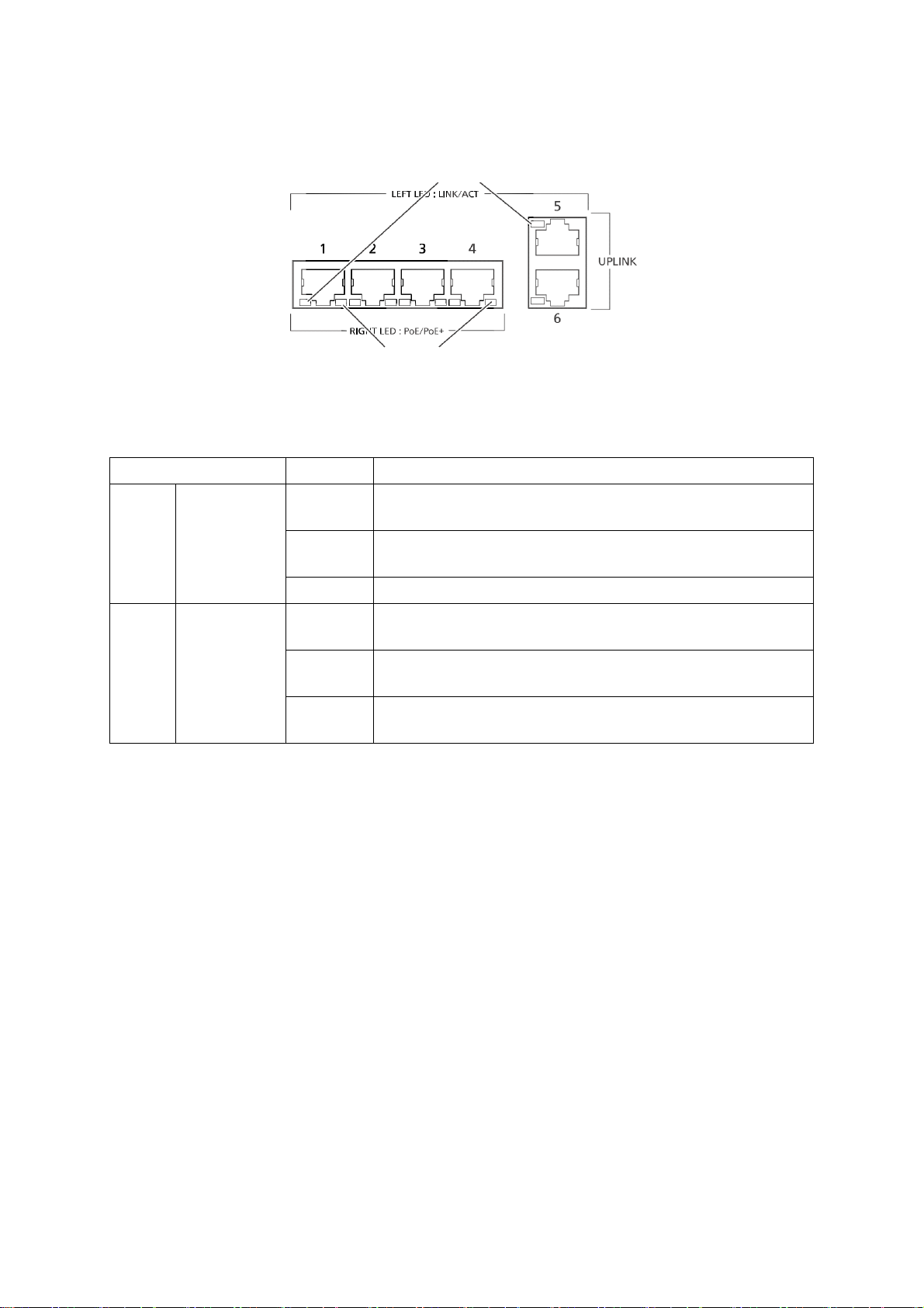
・ Port LEDs
Port LED (Left)
Port LED (Right)
Figure 1-3 Port LEDs (Example: GA-AS10TPoE+)
Port LEDs Behavior Description
Left LINK/ACT Green
Link established.
light
Green
Transmitting data.
blink
Off No device connected.
Right PoE
(PoE support device
only)
Green
light
Green
blink
Supplying power normally.
The whole unit or the single port is overloaded.
Off Not supplying power, or no PoE power receiving
device connected.
17

1.5.3. Operation Overview of PoE Power Supply Func-
tion on PoE Supported Models
The downlink ports of GA-AS4TPoE+/AS10TPoE+/AS12TPoE+ can provide PoE
power supply for IEEE802.3at/af compatible devices. A single port can supply
power up to 30 W.
The number of downlink ports and amount of power supply by the whole unit are
shown below for each model.
Model name Number of downlink ports
(PoE power supply supported)
GA-AS4TPoE+ 4 (port 1 to 4) 62 W
GA-AS10TPoE+ 10 (port 1 to 10) 70 W
GA-AS12TPoE+ 12 (port 1 to 12) 84 W
・ Power supply operation when the PoE LIM. LED is orange blink (the whole unit
is overloaded)
When the whole unit is overloaded due to a power request exceeding the limit,
you can check which port has stopped supplying power, by checking whether
the port LED (right) is green blink. To keep power request less than maximum
power supply on the whole unit, unplug the cable connected to the port green
blink.
Priority control of the power supply can be set and changed from the web control screen. (By factory default, the priority of all downlink ports is set as the
same.)
・ Power supply operation when a single port is overloaded
When power request exceeds the maximum on a single port, the port is overloaded and stops supplying power. You can check which port has stopped supplying power, by checking whether the port LED (right) is green blink. Unplug
the cable on the port green blink.
Power supply by the
whole unit
Note: Power consumption may be greatly different between during normal opera-
tion and during maximum power consumption depending on the PoE power
receiving device. Configure the switch not to exceed the limit.
Note: When priority control is not set or the priority is set as the same for all ports,
the port with the smallest port number will be given priority for power supply.
(If power request exceeds the limit of the whole unit, a port with a larger port
number is blocked to stop supplying power.)
18

2. Installation
For the installation methods for each model, refer to the operating instructions
(paper) provided with each switch.
19
3. Connection
Within 100 m
Within 100 m
Within 100 m
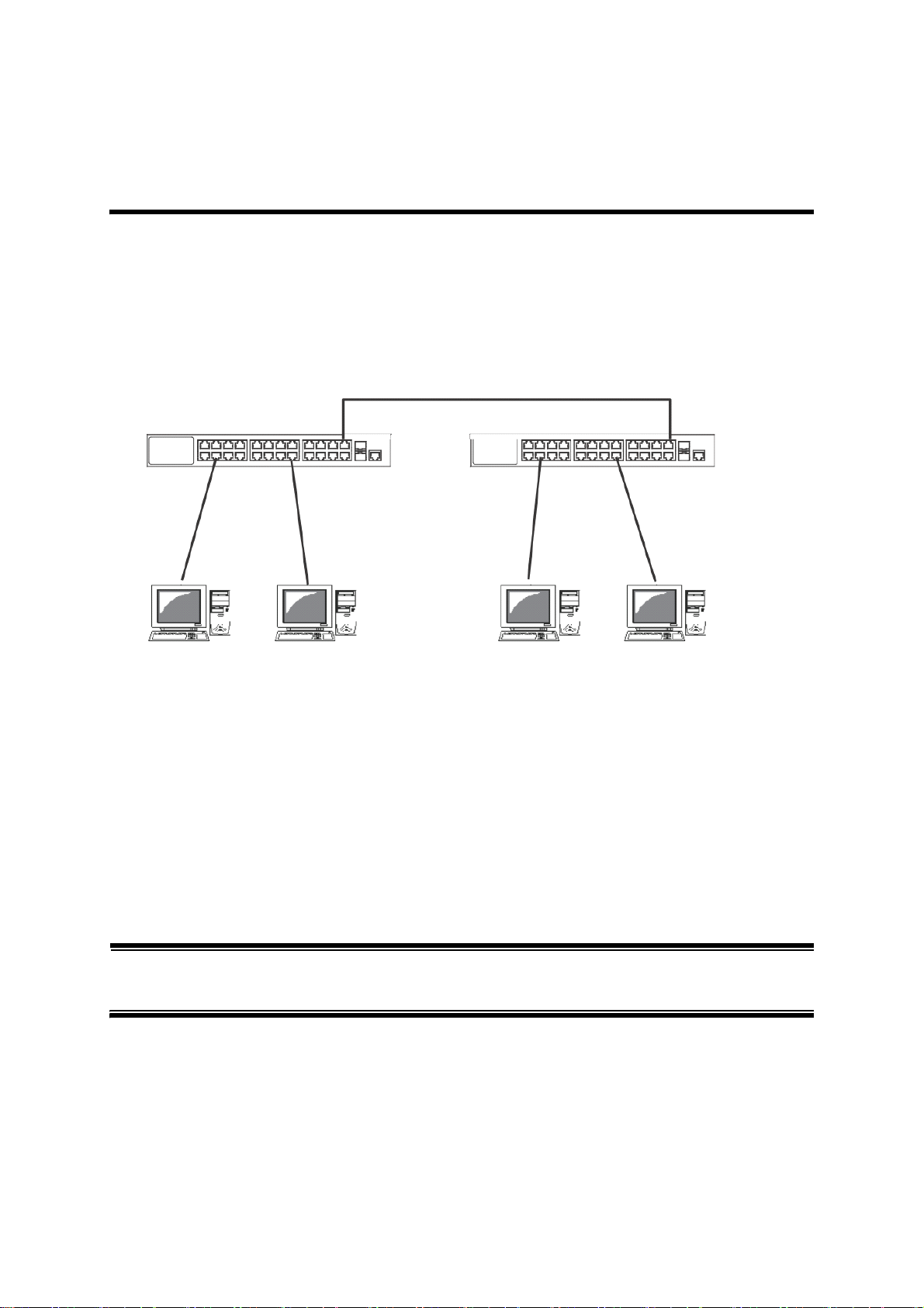
3.1. Connecting a Twisted Pair Port
・ Connection Cable
Use a CAT5E or higher straight cable (twisted pair cable) with 8P8C RJ45 modular plugs.
・ Network Configuration
Figure 3-1 Connection configuration example
The length of the cable connecting this switch and a device must be 100 m or
shorter. When a terminal or a LAN device with auto-negotiation function is connected to a port, the port is automatically configured to the most appropriate performance mode. When a terminal or a device without auto-negotiation function is
connected to a port, this switch automatically determines and sets the communication speed; however, the full-duplex/half-duplex configuration is set at half-duplex
because the full-duplex/half-duplex capability cannot be determined. When connecting a terminal or a device without auto-negotiation function, set the connection mode of the port to Fixed. For detailed configuration procedure, refer to
Section 5.1.3.
Note: If connection mode is set to a fixed value, Auto-MDI/MDI-X function does not
work. Therefore, you need to use a cross cable for connections between
switches.
20

3.2. Connecting to Power
Connect the supplied power cord to the power port of this switch, and connect
the power plug into an electric outlet.
The switch operates at AC 100-240 V (50/60 Hz).
It does not have a power switch. When you connect the power plug, the switch
turns on and starts operating.
To power off, unplug the power plug from the electric outlet.
21

4. Web Browser-based Control
With the web browser-based control function (hereinafter referred to as the "Web
control function"), you can configure the settings for this switch from a web
browser's user interface via the network.
4.1. Operating Environment
The terminal to be accessed should have Microsoft Internet Explorer 11 installed.
Also, the terminal needs to directly connect to a network or this switch.
Note: When you use a proxy, the active window may not be displayed properly;
direct access without using a proxy is recommended.
22

4.2. IP Address Configuration
The IP address of this switch is not set as factory default. To access the Web control function screen for this switch, you need to use the ZEQUO assist Plus application included in the CD-ROM provided with the switch to set the IP address.
For details, refer to the operating instructions (paper) provided with each switch or
the operation instructions for ZEQUO assist Plus.
23
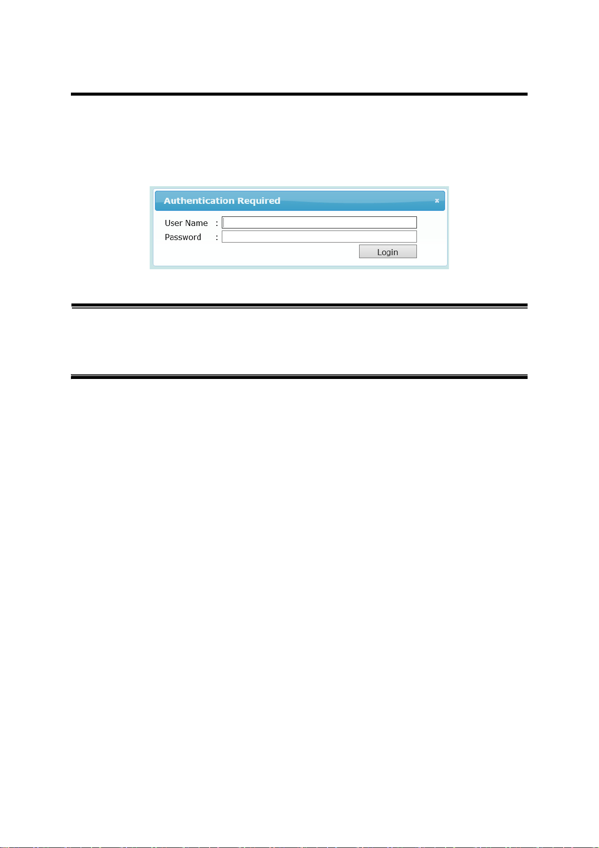
4.3. Access to Web Control Function
To use the Web control function, enter the IP address for this switch in the web
browser's URL field ("location:", "address:", etc.) and press "Enter." Then, a login
screen for this switch shown in Figure 4-1 is displayed. Enter the user name and
password.
The factory default user name is "manager" and password is "manager."
Figure 4-1 Login Screen
Note: If the login screen is not displayed, check the following:
(1) Are the IP address, subnet mask, and default gateway of this switch
properly configured?
(2) Is the IP address entered on the web browser the same as the IP
address of this switch?
24
Loading...