


Operating and Installation Instructions Mode d'emploi et notice d'installation Instrucciones de uso e instalación
Range Hood Hotte de cuisine Campana de cocina
Model No. |
FV-36RBQL1HD |
Modèle |
|
Nº de modelo |
(Hood / Hotte / Campana) |
|
|
Model No. |
FV-36RBQL1MT |
Modèle |
|
Nº de modelo |
(Motor / Moteur / Motor) |
|
READ AND SAVE THESE INSTRUCTIONS
Thank you for purchasing this Panasonic product.
Please read these instructions carefully before attempting to install, operate or service the Panasonic product. Please carefully read the “GENERAL SAFETY INFORMATION” Failure to comply with instructions could result in personal injury or property damage. Please explain to users how to operate and maintain the product after installation, and this booklet should be presented to users.
Please retain this booklet for future reference.
LIRE ET CONSERVER CE DOCUMENT
Nous vous remercions d'avoir acheté ce produit Panasonic. Veuillez lire attentivement ces instructions avant d’essayer d’installer, d’utiliser ou de réparer ce produit Panasonic. Veuillez également lire attentivement la section “CONSIGNES DE SÉCURITÉ” .
Le non-respect des instructions peut entraîner un risque de blessure corporelle et
de dommages matériels. Veuillez expliquer aux utilisateurs comment utiliser et effectuer l’entretien de ce produit après l’installation et leur présenter ce document.
Conservez ce document pour référence ultérieure.
LEA Y CONSERVE ESTAS INSTRUCCIONES
Gracias por comprar este producto Panasonic. Lea atentamente estas instrucciones antes de instalar, utilizar o mantener este producto Panasonic. Lea atentamente el capítulo “INFORMACIÓN GENERAL SOBRE SEGURIDAD”. El incumplimiento de las instrucciones podría causar daños personales o materiales. Explique a los usuarios cómo utilizar y mantener el producto después de la instalación. Se recomienda ofrecer este manual a los usuarios. Conserve este manual para consultas futuras.
ESPAÑOL FRANÇAIS ENGLISH

CONTENTS
GENERAL SAFETY INFORMATION |
................................................................................................................................................................... 3 |
SUPPLIED ACCESSORIES.................................................................................................................................................................................... |
8 |
OPERATION............................................................................................................................................................................................................. |
9 |
USING THE REMOTE CONTROL...................................................................................................................................................................... |
10 |
MAINTENANCE.................................................................................................................................................................................................... |
11 |
DIMENSIONS........................................................................................................................................................................................................ |
12 |
WIRING DIAGRAM ............................................................................................................................................................................................. |
15 |
SPECIFICATIONS................................................................................................................................................................................................. |
15 |
INSTALLATION..................................................................................................................................................................................................... |
16 |
PRODUCT SERVICE ........................................................................................................................................................................................... |
25 |
2

GENERAL SAFETY INFORMATION
For Your Safety
To reduce the risk of injury, loss of life, electric shock, fire, malfunction, and damage to equipment or property, always observe the following safety precautions.
Explanation of symbol word panels
The following symbol word panels are used to classify and describe the level of hazard, injury, and property damage caused when the denotation is disregarded and improper use is performed.

 WARNING

 CAUTION
Denotes a potential hazard that could result in serious injury or death.
Denotes a hazard that could result in minor injury.
The following symbols are used to classify and describe the type of instructions to be observed.
This symbol is used to alert users to a specific operating procedure that must be followed in order to operate the unit safely.
This symbol is used to alert users to a specific operating procedure that must not be performed.
ENGLISH
3

 WARNING
TO REDUCE THE RISK OF A RANGE TOP GREASE FIRE:
a)Never leave surface units unattended at high settings. Boilovers cause smoking and greasy spillovers that may ignite. Heat oils slowly on low or medium settings.
b)Always turn hood ON when cooking at high heat.
c)Clean ventilating fans frequently. Grease should not be allowed to accumulate on fan or filter.
d)Use proper pan size. Always use cookware appropriate for the size of the surface element.
TO REDUCE THE RISK OF INJURY TO PERSONS IN THE EVENT OF A RANGE
TOP GREASE FIRE, OBSERVE THE FOLLOWING:
a)SMOTHER FLAMES with a close-fitting lid, cookie sheet, or metal tray, then turn off the burner. BE CAREFUL TO PREVENT BURNS. If the flames do not go out immediately, EVACUATE AND CALL THE FIRE DEPARTMENT.
b)NEVER PICK UP A FLAMING PAN – You may be burned.
c)DO NOT USE WATER, including wet dishcloths or towels – a violent steam explosion will result.
d)Use an extinguisher ONLY if:
1)You know you have a Class ABC extinguisher, and you already know how to operate it.
2)The fire is small and contained in the area where it started.
3)The fire department is being called.
4)You can fight the fire with your back to an exit.
Based on “ Kitchen Firesafety Tips ” published by NFPA.
TO REDUCE THE RISK OF FIRE, ELECTRIC SHOCK, OR INJURY TO PERSONS,
OBSERVE THE FOLLOWING:
a) Use this unit only in the manner intended by the manufacturer. If you have questions, contact the manufacturer.
b)Before servicing or cleaning unit, switch power off at service panel and lock the service disconnecting means to prevent power from being switched on accidentally. When the service disconnecting means cannot be locked,
securely fasten a prominent warning device, such as a tag, to the service panel.
GROUNDING INSTRUCTIONS
a)This appliance must be grounded. In the event of an electrical short circuit, grounding reduces the risk of electric shock by providing an escape wire for the electric current. This appliance is equipped with a cord having a grounding wire with a grounding plug. The plug must be plugged into an outlet that is properly installed and grounded.
b)Improper grounding can result in a risk of electric shock.
c)Consult a qualified electrician if the grounding instructions are not completely understood, or if doubt exists as to whether the appliance is properly grounded.
d)Do not use an extension cord. If the power supply cord is too short, have a qualified electrician install an outlet near the appliance.
4

WARNING |
|
|
TO REDUCE THE RISK OF FIRE, ELECTRIC SHOCK, OR INJURY TO PERSONS, |
|
|
OBSERVE THE FOLLOWING: |
|
|
|
|
|
a) Installation work and electrical wiring must be done by qualified person(s) in accordance with all applicable |
|
|
codes and standards, including fire-rated construction. |
|
|
|
|
|
b) Sufficient air is needed for proper combustion and exhausting of gases through the flue (chimney) of fuel |
|
ENGLISH |
burning equipment to prevent back drafting. Follow the heating equipment manufacturer’s guideline and safety |
|
|
|
|
|
standards such as those published by the National Fire Protection Association (NFPA), and the American Society |
|
|
for Heating, Refrigeration and Air Conditioning Engineers (ASHRAE), and the local code authorities. |
|
|
|
|
|
c) When cutting or drilling into wall or ceiling, do not damage electrical wiring and other hidden utilities. |
|
|
|
|
|
|
|
|
d) Ducted fans must always be vented to the outdoors. |
|
|
-Clean the filters and all laden surfaces on a regular basis.
-To provide protection against electric shock, connect to properly grounded outlets only.
-To reduce the risk of fire, use only metal ductwork.
-Stop using the unit when any abnormality / failure occurs and turn “OFF” the power switch or pull out the 3 pin plug. Example of abnormality failure:
-Abnormal noise or heat.
-Abnormal emission of smell / smoke.
-Fire or oil ignition.
-Insert the Power Plug firmly, otherwise it may cause fire or electric shock.
-The supply cord must be set properly not to be damaged. The manufacturer declines all liability if the safety standards are not observed.
-The socket used to connect the installed equipment to the electrical power supply must be within reach: otherwise, install a mains switch to disconnect the Range Hood when required.
-The wall plugs must have a secure grip.
-The enclosed screws and wall plugs are suitable for solid brickwork or solid concrete. Suitable fasteners must be used for other structures (e.g. plasterboard, porous concrete, porous bricks).
-The maximum length of the flue fastening screws (supplied by the manufacturer) must be 0 33/64" (13mm). Use of non-compliant screws with these instructions can lead to danger of an electrical nature.
-Keep in mind that installations with different types of fastening systems from those supplied, or which are not compliant, can cause electrical and mechanical seal danger.
-Clean the Power Plug regularly with dry cloth, otherwise it may cause insufficient insulation due to moisture, and may cause fire.
-There is a fire risk if cleaning is not carried out in accordance with the instructions.
-Accessible parts may become hot when used with cooking appliances.
-Always supervise the cooking process during the use of deep-fryers: Overheated oil can catch fire.
-A statement to the effect that when the product is to no longer be used, it must not be left in place but remove, to prevent it from possibly failing.
-Always check that all the electrical parts (lights, exhaust device), are off when the appliance is not being used.
-This appliance is not intended for use by young children or infirm persons unless they have been adequately supervised by a responsible person to ensure that they can use the appliance safely. Young children should be supervised to ensure they do not play with the appliance.
-To reduce the risk of fire, electric shock, and injury to persons, Range Hood must be installed with Range Hood Motor Unit that are marked on their cartons to indicate the suitability with this model. Other cannot be substituted.
-To reduce the risk of fire or electric shock, do not use this fan with any solid-state speed control device.
-Do not connect the appliance to flues (from boilers, fireplaces, etc.).
-Do not discard the packaging or any part of it, or leave it unattended.
It can constitute a suffocation hazard for children, especially the plastic bags.
-Do not flambé under the Range Hood.
-Never cook on “open” flames under the Range Hood.
-Do not leave open, unattended flames under the Range Hood.
-Do not switch “OFF” or “ON” the Range Hood when there may be a gas leak in your gas hob. Gas explosion may result in.
-Do not handle the Power Plug with wet hand, otherwise it may cause electric shock.
-Do not disassemble the unit for reconstruction.
5

 CAUTION
-Use the neutral detergent only.
-For residential use only.
-The minimum distance between supporting surface for the cooking vessels on the hob and lowest part of the Range Hood must be at least 36" (914 mm).
-To reduce risk of fire and to properly exhaust air, be sure to duct air outside.
-Before the appliance is put into operation, all the protective film must be removed.
-Check whether the Range Hood is installed securely and horizontally.
-Always operate the Range Hood when using gas cooker.
-Avoid parts from falling when detaching it for cleaning.
-Ensure that the wires inside the Range Hood are not disconnected or cut: in the event of damage, contact your nearest Servicing Department.
-When disconnect the Power Plug, hold the plug itself. Do not pull the cord anyway. The cord may be damaged, it may cause fire or electric shock.
-Be sure to disconnect the Power Plug from the wall outlet or switch off the breaker when not using for a long time.
-Product must be installed on the ceiling, which is strong enough to hold the unit. Reinforce it if necessary.
-The Range Hood should be installed so that the metal part of the product and mounting screw do not contact with any metalic item inside the wall, such as metal laths, wire laths and metal plate, it is possible to cause fire harzards in case of electrical leak.
-During installation, always use personal protective equipment (e.g.: Safety shoes, gloves) and adopt prudent and proper conduct.
-Please wear gloves during the cleaning work.
-Make sure that the electric service supply voltage is AC 120 V, 60 Hz.
-Protect the supply wiring from sharp edges, oil, grease, hot surfaces, chemicals or other objects.
-Suitable for use in a household cooking zone.
-Before installing the Range Hood, check the integrity and function of each part. Should anomalies be noted, do not proceed with installation and contact the Dealer.
-Do not vent exhaust air into spaces within walls or ceilings or into attics, crawl spaces, or garages.
-For general ventilating use only. Do not use to exhaust hazardous or explosive materials and vapors.
-It is dangerous to modify or attempt to modify the characteristics of this system.
In the event of malfunctions or if repairs are required to the appliance, do not attempt to solve the problems directly. Repairs performed by unqualified persons may cause damage. For all repair and other work on the appliance, contact the service centre.
-Insist on original spare parts.
-Do not insert pointed metal objects (cultery or utensils) into any aperture in the Range Hood.
-Do not use a steam cleaner for cleaning the appliance. The steam could reach the electronics, damaging them and causing short-circuits.
-Do not use too much moisture or water around the push button control panel and lighting devices in order to prevent humidity from reaching electronic parts.
-Do not clean electrical parts, or parts related to the motor inside the Range Hood, with liquids or solvents.
-Never use petrol, benzene, thinner or any other similar chemicals to clean the product.
-Do not use abrasive products.
-Do not carry out any cleaning operations when parts of the Range Hood are still hot.
-Never use the product in a wet place. It may cause fire or failure.
-During operation, never insert fingers or other objects into any aperture in the Range Hood. Failure or injury may result in.
-Do not put anything on the Range Hood. It may cause fire, failure or injury.
-Do not kink the supply wiring.
-Never use the Range Hood without the metal filters:
in this case, grease and dirt will deposit in the equipment and compromise its operation.
6

FCC and other information
•The remote control complies with part 15 of the FCC Rules. Operation is subject to the following two conditions:
(1)The remote control may not cause harmful interference, and
(2)The remote control must accept any interference received, including interference that may cause undesired operation.
•This transmitter must not be co-located or operated in conjunction with any other antenna or transmitter.
FCC CAUTION
Changes or modifications not expressly approved by the party responsible for compliance could void the user’s authority to operate the equipment.
FCC RF EXPOSURE COMPLIANCE
The remote control complies with FCC radiation exposure limits set forth for an uncontrolled environment and meets the FCC radio frequency (RF) Exposure Guidelines. The remote control has very low levels of RF energy that is deemed to comply without testing of specific absorption rate (SAR).
FCC RF EXPOSURE WARNING
•The remote control complies with FCC radiation exposure limits set forth for an uncontrolled environment.
•The remote control may not be collocated or operated in conjunction with any other antenna or transmitter.
•For body-worn operation, the device must be used only with a non-metallic accessory. Use of other accessories may not ensure compliance with FCC RF exposure requirements.
Notice
FCC ID can be found on the rated plate in the Remote Control.
Other notices and information (for Canada)
The remote control complies with Industry Canada’s licence-exempt RSSs. Operation is subject to the following two conditions:
(1)The remote control may not cause interference; and
(2)The remote control must accept any interference, including interference that may cause undesired operation of the device.
RF EXPOSURE COMPLIANCE
The remote control complies with IC radiation exposure limits set forth for an uncontrolled environment and meets RSS-102 of the IC radio frequency (RF) Exposure rules. The remote control has very low levels of RF energy that is deemed to comply without testing of specific absorption rate (SAR).
RF EXPOSURE WARNING
•The remote control complies with ISED radiation exposure limits set forth for an uncontrolled environment.
•The remote control may not be collocated or operated in conjunction with any other antenna or transmitter.
ENGLISH
7
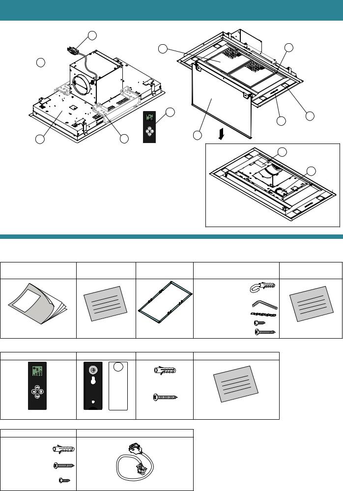
SUPPLIED ACCESSORIES
Part identification : |
10 |
|
5 |
8 |
6 
|
|
|
11 |
|
3 |
2 |
|
|
|
|
|
||
|
|
|
|
|
|
|
|
1 |
|
9 |
4 |
|
|
|
|
|
|
|
||
1 |
- Range Hood body |
|
|
|
7 |
|
2 |
- LED spotlight illumination x 4 |
|
|
|
|
|
3 |
- Electronic pushbutton |
8 - Magnet x 2 |
|
|
12 |
|
4 |
- Perimeter suction panel |
9 - Support bracket x 2 |
|
|
|
|
5 |
- Metal filter x 2 |
10 |
- Power cord |
|
|
|
6 |
- Motor unit |
11 |
- Remote control |
|
|
|
7 |
- Name plate |
12 |
- Module support for add-on |
|
|
|
|
|
|
Module that provides additional |
|
|
|
|
|
|
features (Module sold separately) |
|
|
|
Supplied accessories : - Hood unit
A - Operating and |
B - Warranty sheet |
C - Protection |
installation instructions |
|
Template |
and |
sheet |
|
Warranty |
|
|
Operating |
|
|
installation |
|
|
instructions |
|
|
1 pc |
2 pcs |
1 pc |
- Remote control |
|
|
A - Remote control |
B - Holder |
C - Screw pack |
ø6 mm wall plug (2 pcs)
|
|
|
ø4.5x40 mm |
1 pc |
1 pc |
1 pc |
(2 pcs) |
- Motor unit |
|
|
|
A - Screw pack |
B - Extension cable |
|
|
ø8 mm wall plug |
|
|
|
(4 pcs) |
|
|
|
ø5×50 mm (4 pcs) |
|
|
|
ø4.2×12.5 mm (5 pcs) |
|
1 pc |
|
|
|
|
|
Wall plugs are for solid brickwork or solid concrete.
D - Screw pack |
E - Caution paper |
|
Wall plug & eye |
|
|
(2 pcs) |
paper |
|
Allen key (1 pc) |
Caution |
|
|
||
Safety chain (2 pcs) |
|
|
ø3.9×9.5 mm (6 pcs) |
1 pc |
|
ø5×50 mm (2 pcs) |
||
|
||
D - Instructions |
|
|
Instruction |
|
1 pc
8

OPERATION
WHEN TO TURN ON THE RANGE HOOD?
Turn on the Range Hood at least one minute before starting to cook to direct fumes and vapours towards the suction surface.
After cooking, leave the Range Hood operating until complete extraction of all vapours and odours. By means of the Timer function, it is possible to set auto switch-off function which will allow
the Range Hood to turn off automatically after 15 minutes of operation.
WHICH SPEED IS TO BE SELECTED?
1st speed : disposal of odours and vapours with low electricity consumption. 2nd speed : normal conditions of use.
3rd speed : presence of strong odours and vapours. 4th speed : rapid disposal of odours and vapours.
WHEN SHOULD THE FILTERS BE WASHED?
It is advised to wash the metal filters every 30 hours of operation.
For further details refer to the “MAINTENANCE” section.
ELECTRONIC PUSHBUTTON PANEL
Motor ON / OFF
Upon start-up, the speed is that stored at the previous operation.
Increase speed from 1 to 4
Speed 4 is only active for 7 minutes, speed 3 activates.
Reduce speed from 4 to 1
The speeds are indicated by the LEDs on the keys :
("+" LED flashing)
Speed |
Speed |
Speed |
Speed |
1 |
2 |
3 |
4 |
Light on / off
TIMER (red LED flashing) Auto switch-off after 15 min.
This function can be activated only if the motor is already active with any speed when the key is pressed.
The function deactivates (red LED off) if :
-The TIMER key ( 


 ) is pressed again.
-The ON / OFF key ( ) is pressed.
FILTER ALARM (red LED steady on with ( ) off)
The RED lighting indicates that the metal filter alarm is active (after 30 hours); to deactivate this alarm and reset the hour meter, press the key ( ) for 3 seconds.
ENGLISH
9

USING THE REMOTE CONTROL
WARNING! :
Place the Range Hood away from sources of electromagnetic waves (e.g. microwave ovens), which could interfere with the remote control and with the Range Hood electronics.
IMPORTANT :
If motor is turned on by remote control and then tuned off by electric push button of hood unit, the motor may be turned on when pushing button of Light ON-OFF or TIMER ON on remote control, because last setting of remote control is remained.
DESCRIPTION OF TRANSMITTING COMMANDS
UP
Motor switch-on and speed increase from 1 to 4. Speed 4 is only active for 7 minutes.
DOWN
Speed decrease and motor switch-off.
Speed 4 Speed 3
  Speed 2
  Speed 1
 OFF
OFF
Light ON-OFF
TIMER ON : The motor automatically switches off after 15 min.
The function is automatically disabled if the motor is switched off ( key)
key)
Command transmission active
REMOTE CONTROL CODE CHANGE
The maximum operating distance is 5 meters, that may vary according to the presence of electromagnetic interferences.
Remote control operated at 433.92MHz. The remote control consists of two parts :
-the receiver built into the Range Hood;
-the transmitter shown here in the figure.
With only one remote control, go directly to point 2.
With several remote controls in the same room, a new code can be created by following the procedure below.
Disconnect the power to the Range Hood before starting the procedure.
1) - CREATE A NEW CODE
The procedure is to be carried out on the remote control.
•Press LIGHT  and TIMER
  simultaneously until the display starts flashing.
•Press DOWN  on the remote control : saving is confirmed by three brief flashes of the display.
The new code cancels and replaces the previous default code.
Reconnect the Range Hood to the electrical power supply, making sure that the lights and motor are off.
2) - ASSOCIATING THE REMOTE CONTROL WITH THE RANGE HOOD USING THE ELECTRONIC PUSHBUTTON PANEL Press TIMER ( ) on the Range Hood pushbutton panel for 2 seconds :
- The red LED lights up.
- Press any key on the remote control within 10 seconds.
RESTORING DEFAULT CODE
The procedure is to be carried out if the Range Hood is disposed of, sold or transferred.
Disconnect the power to the Range Hood before starting the procedure.
•Press UP  and DOWN
  simultaneously on the remote control for more than 5 seconds : reset is confirmed by three brief flashes of the display.
•Reconnect the Range Hood to the electrical power supply.
•Proceed with associating the Range Hood and the remote control, as described in point 2.
10
MAINTENANCE
|
Before servicing or cleaning unit, switch power off at service panel and lock the service |
|
WARNING |
disconnecting means to prevent power from being switched on accidentally. |
|
When the service disconnecting means cannot be locked, securely fasten a prominent |
||
|
||
|
warning device, such as a tag, to the service panel. |


 CAUTION
 Please wear gloves during the cleaning work.
Regular maintenance guarantees proper operation and performance over time.
Special attention is to be paid to the metal filters: frequent cleaning of the metal filters and their supports ensures that no flammable grease is accumulated.
CLEANING OF EXTERNAL SURFACES
You are advised to clean the external surfaces of the Range Hood at least once every 15 days to prevent oily substances and grease from sticking to them.
Alternatively and for all the other types of surfaces, it can be cleaned using a damp cloth, slightly moistened with mild, liquid detergent or denatured alcohol.
Complete cleaning by rinsing well and drying with soft cloths.
Do not use products that contain abrasive substances or cloths NOT specifically designed for cleaning steel. The Manufacturer declines all responsibility for failure to comply with these instructions.
CAUTION |
Be careful when removing the perimeter suction panel in case oil has accumulated on it and |
|
may fall out. |
||
|
CLEANING OF INTERNAL SURFACES
Do not clean electrical parts, or parts related to the motor inside the Range Hood, with liquids or solvents.
METAL FILTERS
It is advised to frequently wash the metal filters (every 30 hours of operation and at least once a month) leaving them to soak in boiling water and cleaning solution for 1 hour, taking care not to bend them.
-Do not use corrosive, acid or alkaline detergents.
-Rinse them well and wait for them to be completely dry before reassembling them.
-Washing in a dishwasher is permitted, however, it may cause the metal filter material to darken: to reduce the possibility of this problem from happening, use low-temperature washes (131 °F/ 55 °C max.).
To remove the perimeter suction panel and the metal filters as shown figure below.
ENGLISH
How to remove of the metal filters
How to remove of the perimeter suction panel
|
2 |
|
4 |
1 |
3 |
2 |
1 |
|
|
|
3 |
|
11 |

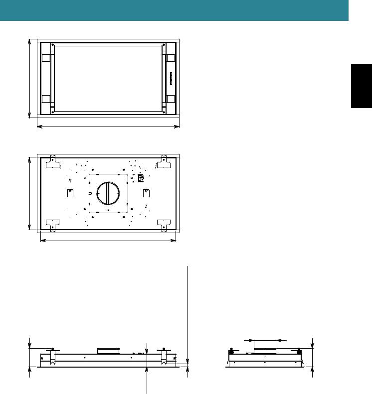
DIMENSIONS (Assembled Hood unit and Motor unit)
21 1/4" - 540 mm |
|
|
|
38 1/4" - 973 mm |
|
19 3/8" - 492 mm |
21 7/8" - 556 mm |
|
|
14 5/8" - 370 mm |
|
|
36 3/8" - 925 mm |
|
|
|
25 mm |
|
10 7/8" - 275 mm |
min. 3/8" / max. 1" min. 10 mm / max. |
128 mm |
Ø 5 7/8" Ø 150 mm |
|
5" - |
1/2" mm |
|
|
3 |
89 |
10 7/8" - 275 mm
mm |
mm |
1/8"9 |
1/4"13 |
233 |
335 |
12
DIMENSIONS (Remote Motor unit installation)
21 1/4" - 540 mm |
ENGLISH |
|
38 1/4" - 973 mm |
19 3/8" - 492 mm
36 3/8" - 925 mm
mm128 |
|
25 mm |
|
/"3/8min.max. mm10min./ max. |
|
|
|
1" |
5" - |
1/2" mm |
|
|
3 |
89 |
Ø5 7/8"
Ø150 mm
4 7/8" 125 mm
13
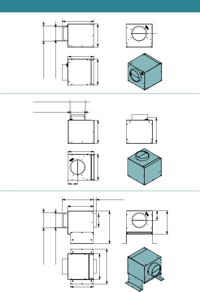
DIMENSIONS (Motor unit)
|
|
13 1/4" - 336 mm |
3/8"6Ø- Ø 162 mm (Outeradaptor) |
7/8"5Ø- Ø 150 mm (Inneradaptor) |
- 245 mm |
275-7/8"mm 9 5/8" |
||
|
|
10 7/8" - 275 mm |
|
|
10 |
Ø6 3/8" - Ø 162 mm
(Outer adaptor) 
Ø 5 7/8" - Ø 150 mm |
|
|
|
(Inner adaptor) |
|
|
|
|
|
9 5/8" - 245 mm |
|
|
10 7/8" - 275 mm |
|
|
|
|
9 5/8" - 245 mm |
|
|
4" - 103 mm |
|
|
|
13 1/4" - 336 mm |
1 3/8" - 35 mm |
|
|
10 7/8" - 275 mm |
|
|
|
|
7/8" |
mm |
|
|
mm |
346.4 |
|
|
Ø |
|
|
|
149 |
|
|
|
5 |
|
|
|
Ø |
|
Ø 6 3/8" - Ø 162 mm (Outer adaptor) |
Ø 5 7/8" - Ø 150 mm (Inner adaptor) |
|
13 5/8" - |
10 7/8" - 275 mm |
14 3/4" - 375 mm |
||
|
9 1/2" - 240 mm |
|
|
 5 5/8" - 144 mm
10 1/2" - 268 mm |
4" |
mm |
mm |
|
102 |
245 |
|
9 5/8" - |
14
|
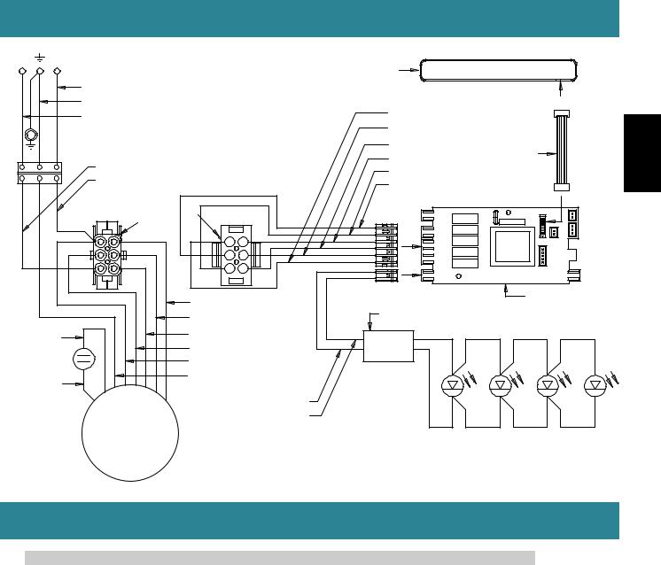
WIRING DIAGRAM |
|
|
|
L |
N |
CONTROL PANEL |
|
|
|
|
|
|
|
|
WHITE |
|
|
|
|
GREEN |
WHITE (2° SPEED) |
|
5 V |
|
BLACK |
|
|
|
|
ORANGE (4° SPEED) |
|
||
|
|
|
||
|
|
GRAY (LINE) |
FLAT CABLE |
|
|
BROWN |
RED (NEUTRAL) |
|
|
|
|
|
||
|
BLACK (3° SPEED) |
|
|
|
|
BLUE |
|
|
|
|
BLUE (1° SPEED) |
|
|
|
|
|
|
|
|
REAR VIEW PIN |
PIN |
REAR VIEW |
|
|
|
|
|||
4 |
1 |
1 |
4 |
|
5 |
2 |
2 |
5 |
|
6 |
3 |
3 |
6 |
|
|
|
WHITE (2° SPEED) |
MAIN BOARD |
|
|
|
TRANSFORMER |
||
|
|
BLUE (1° SPEED) |
||
|
|
|
||
BROWN |
|
GRAY (3° SPEED) |
12 V |
|
|
BLACK (4° SPEED) |
|||
|
|
|||
|
|
|
||
|
|
RED |
|
|
YELLOW |
|
YELLOW - GREEN |
|
|
|
|
|
|
|
|
|
|
BROWN |
|
|
M |
|
BLUE |
|
|
|
|
|
|
|
~ |
|
|
LED LIGHT SPOT |
|
|
|
|
|
SPECIFICATIONS
Model No. |
|
FV-36RBQL1 |
|
Voltage |
|
|
AC 120V |
Frequency |
|
|
60 Hz |
|
4th Speed |
|
338 |
Power (W) |
3rd Speed |
|
233 |
2nd Speed |
|
177 |
|
|
|
||
|
1st Speed |
|
143 |
Air Volume |
4th Speed |
|
440 |
3rd Speed |
|
340 |
|
at 0.1" WG (CFM) |
|
|
|
2nd Speed |
|
240 |
|
|
|
||
|
1st Speed |
|
130 |
|
4th Speed |
|
8.0 |
Noise (sones) |
3rd Speed |
|
5.5 |
2nd Speed |
|
3.0 |
|
|
|
||
|
1st Speed |
|
1.4 |
Lamp |
|
|
3.6 W x 4 |
Pipe Diameter |
|
Ø5 7/8" ( Ø150 mm ) |
|
Dimensions (L x W x H) |
|
38 1/4" x 21 1/4" x 3 1/2" ( 973 mm x 540 mm x 90 mm) |
|
Weight |
|
Range Hood Body 47 lb. (21 kg ) |
|
|
Motor Unit |
20 lb. ( 9 kg ) |
|
|
|
||
HVI Certified performance based on HVI Procedures 915, 916, and 920.
ENGLISH
15

INSTALLATION
Before installing the Range Hood, carefully read Chap. "GENERAL SAFETY INFORMATION".
CAUTION |
The ceiling must support the weight of the hood (89 lb. - 40 kg max.). |
Install the reinforcement wood frame to hold ceiling board so that ceiling board hold load of Range hood.
Note :
The recommended distance between the highest part of the cooker and the lowest part of the Range Hood is approximately 43 5/16" (1100 mm).
In certain cases, this distance can be increased up to a maximum of approximately 72" (1829 mm) with a slight decrease in the efficiency of the device.
The minimum installation distance must not be less than 36" (914 mm).
Should the instructions for the gas cooker specify a greater distance, take this into consideration.
Install reinforcement wooden frames to hold the ceiling board as shown below in (Fig. 1 ).
Make a hole in the ceiling as indicated in (Fig. 2 ).
A |
|
|
1 |
Reinforcement wooden frame |
1 31/32” |
50 mm |
||
|
|
1 13/16” 46 mm |
|
Joist |
|
|
Cutout |
|
|
Joist |
|
Min.36" Min.914 mm Max.72" 1829Max. mm |
|
Ceiling |
|
)mm |
|
|
Reinforcement wooden frame |
|
2 |
Cutout dimensions |
|
|
|
19 7/8” ( 505 |
|
37” ( 940 mm ) |
|
|
If ceiling is not strong enough to hold |
|
|
the Range Hood, add reinforcement |
|
|
wood frame to along the cutout. |
|
Joist |
|
1” 25.4 mm |
|
Max. Max. |
|
|
|
|
Ceiling |
|
|
|
|
|
Reinforcement |
|
|
Cutout |
||
wooden frame |
|
|
16

•Bend the flaps (A) of the protection template (B) toward the opposite side to the one with the double-sided adhesive tape. If not, bend them with a suitable tool (e.g. grippers) (Fig. 1 ).
•Remove the film from the doubled-sided adhesive tape already applied on the protection template (B) (Fig. 2 ) and insert it into the hole made on the ceiling, keeping it tilted so that it passes easily (Fig. 3 ).
Complete the operation by fixing the protection template (B) to the ceiling (Fig. 4 |
). |
|
||
B |
|
A |
|
|
3 |
1 |
|
||
|
|
|
Correct |
ENGLISH |
|
A |
|
|
|
|
|
|
|
|
|
|
|
Incorrect |
|
|
2 |
double adhesive |
|
|
4
Reinforcement |
|
wooden frameA |
B |
ceiling
•Mark 2 screw positions on the wood framing (Fig. 1 ).
•Fasten the safety chains to the wood framing with the relative screws (V1 Ø5×50) (Fig. 2 ), they will then be fastened to the Range Hood as a safety support.
C
 Safety chain hole
25/32” |
|
8 |
mm |
223 |
|
V1 |
2 |
2 - Ø5 × 50 |
|
1
chain
8 223
17

INSTALLATION (MOTOR UNIT PLACED ON THE RANGE HOOD)
Refer to Chap. "MAINTENANCE", remove the perimeter suction panel and the metal filters completely.
Hood unit : Remove the flange (C) (Fig. 1 ).
Motor unit : Remove the bracket (D) and the motor flange (E) (Fig. 2 ).
[ In case of duct direction change ]
Unfasten 8 screws and washer, and then remove the flange (F) from the motor unit (G) (Fig. 3 , 4 ) . Define the air outlet direction by rotating the flange (F) (Fig. 5A ).
Securing the flange (F) to the component (H) with 8 screws and washer (Fig. 5B ).
The motor unit (G) can also be installed on the Range Hood in various positions in order to have the desired air outlet direction (Fig. 6 ).
D |
|
|
|
|
|
D (x2) |
|
|
|
|
|
|
2 |
|
|
1 |
|
|
C |
|
V2 |
|
|
|
|
|
|
|
|
||
|
|
|
|
Ø4.2×12.5 |
|
|
|
|
|
|
|
|
Note : |
|
G |
|
|
|
|
|
Keep screws and |
|
|
|
|
|
|
|
washers to install the |
|
|
|
|
|
|
|
motor unit (G) on |
) |
|
|
|
|
|
|
(the Range Hood |
|
|
|
|
|
|
|
4 - washer |
E |
|
|
|
|
|
|
|
|
|
|
|
|
|
|
V3 |
|
|
|
|
|
|
|
8 - Ø3.9×9.5 |
|
|
[ Factory setting ] |
|
[ In case of duct direction change ] |
|
|
|
||
|
|
|
3 |
F |
8 - screw |
|
|
|
|
|
|
|
Ø3.9×9.5 |
|
|
|
|
|
washer |
|
|
|
|
AIR |
|
|
|
|
|
6 |
|
|
|
|
|
|
|
|
|
Motor unit |
|
AIR |
|
|
H |
|
|
G |
|
|
|
|
|
||
|
|
|
|
|
|
|
|
4 |
H |
5A |
washer |
5B |
AIR |
|
|
F |
|
|
|
AIR |
|
||
|
|
|
|
|
|||
|
|
|
|
|
|
||
|
|
|
F |
|
|
|
G |
|
|
|
|
AIR |
|
|
|
|
|
|
|
|
|
|
|
18 |
|
|
|
|
|
|
|

Unfasten screws and remove 2 support brackets (J) from the hood unit (Fig. 1 ).
Secure the support brackets (J) to the motor unit (G) using the 4 screws (V4 Ø3.9×9.5), taking the desired air outlet direction into consideration (Fig. 2 ).
E
2 -1 |
|
2 -2 |
1 |
|
|
|
AI |
R |
|
|
G
V4 J
4 - Ø3.9×9.5
J J
AIR
G
J
V4
4 - Ø3.9×9.5
ENGLISH
The motor used in the motor unit (G) is, by default, equipped with a check valve already installed.
If required, remove them from the air outlet fitting of the motor.
F
G
Check valve
Place the motor unit (G) on the ceiling (Fig. 1 ), taking care to center the assembly by means of the flaps (A) of the protection template (B) (Fig. 2 ).
G |
|
G |
B |
1 |
2 |
A |
|
|
19 |

Connect the air outlet fitting of the motor unit (G) to the pipe (K) set up for external discharge (Fig. 1 ).
Set up the electric connection to power the Range Hood only after having disconnected the main power supply switch and complied with current regulations (Fig. 2 ).
Lift the Range Hood towards the ceiling (Fig. 3 ) and pass the safety chains through the holes of the Range Hood (Fig. 4 ). Insert the Range Hood in the previously reinforced ceiling : as the hooks (L) open, they provisionally support the Range Hood on the ceiling (Fig. 5 ). Tighten all screws (V5) in order to open the hooks (L) and block the Range Hood on the ceiling
(Fig. 6 , 7 ).
H
5 7/8" |
|
|
150 mm |
F |
|
|
G |
|
|
|
2
4
(x2)
G


 1
1


 L 6
L 6
3 |
V5 |
OK! |
|
|
|
|
|
L |
Disassembly!
7 


 L
L


Safety chains |
5 |
|
20
Fasten the motor unit (G) to the Range Hood body using the 8 screws (V3 Ø3.9×9.5) and 4 washers (Fig. 1 ). Connect the motor unit connector (M) to the Hood unit connector (N) (Fig. 2 ).
Fix the safety chains to the Range Hood using the supplied screws (V6 Ø3.9×9.5) and cut the excess chain (Fig. 3 ). Place back the metal filters and the perimeter suction panel carefully, refer to Chap. "MAINTENANCE".
Metal filter protective film must be removed.
I |
|
|
|
|
ENGLISH |
|
|
|
G |
V3 |
|
|
|
(Front side) |
|
8 - Ø3.9×9.5 |
|
1 |
Magnet |
Magnet |
|
|
|
4 - washer |
|
|
|||
|
|
|
|||
|
|
|
|
|
|
|
|
|
|
4 - washer |
|
|
|
|
8 - screw |
|
|
|
|
(Bottom view) |
|
|
|
|
2 |
|
3 |
|
|
|
|
M |
|
|
|
|
|
N |
|
|
|
|
|
|
V6 |
|
|
|
|
|
2 - Ø3.9×9.5 |
|
|
Note : |
|
|
|
|
|
-The exhaust conveyor that protrudes from the upper part of the Range Hood must be connected with the pipe that conducts the fumes and vapours in an external output.
-The fumes and vapours are discharged outside through the exhaust pipe.
To this end, the Range Hood outlet fitting must be connected via a pipe, to an external output.
-The diameter of the fume discharge duct must be no smaller than the Range Hood connection. We recommend using pipes with Ø5 7/8" (Ø150 mm) diameter.
-The outlet pipe must have a diameter not less than that of the Range Hood fitting.
-The outlet pipe must have :
A slight slope downwards (drop) in the horizontal sections to prevent condensation from flowing back into the motor.
The duct must be installed not to bend it in the immediate vicinity of the discharge hole. Otherwise, the return valve will get stuck with the duct, and will not work for the exhaust properly.
Reduce curves to the bare minimum, and check that the length of the ducts is also the bare minimum.
You are required to insulate the pipes if it passes through cold environments.
-The electrical system to which the Range Hood is to be connected must be in accordance with local standards and supplied with earthed connection in compliance with safety regulations in the country of use.
It must also comply with local standards regarding radio antistatic properties.
-Before connecting the Range Hood to the electrical mains power supply, check that : the power supply plug and cable
do not come into contact with temperatures exceeding 158 °F (70 °C);
-Check that the relief valve and the electrical system are able to support the load of the appliance (see the technical specifications displayed on the rated plate in the Range Hood).
21

INSTALLATION (REMOTE MOTOR UNIT)
The Range Hood can be connected to the under-roof (URS) remote motor unit.
In the case of an under-roof motor unit (URS), it must be placed next to the technical compartment inside the home, protected against atmospheric agents and within reach for any maintenance operations.
In the case of installation with remote motor, you must connect the Range Hood to the electrical system earthing (after having verified its functioning) by means of a suitable cable.
To execute this operation, use the threaded insert set up in the Range Hood structure and identified with a label and symbol  . It is recommended that you comply with the current regulations on electrical safety of systems and devices regarding earthing equipment.
Unfasten screws and 4 washers, remove the bracket (D) and the motor flange (E) from the motor unit (G) |
|||||||
(Fig. 1 |
). |
|
|
|
|
|
|
Reassemble to straight exhaust direction by rotating the flange (F) of the motor unit (G) (Fig. |
2 ). |
|
|||||
Secure the brackets (D) to the motor unit (G) using the 6 screws (V2, V7 Ø4.2×12.5) (Fig. |
3 |
). |
|
||||
Additionally install reinforcement wooden frames between the joists in the ceiling (Fig. |
4 |
). |
|
||||
Secure the motor unit (G) to the reinforcement wooden frame using the 4 screws (V8 Ø5×50) (Fig. |
5 ). |
||||||
J |
|
|
|
|
|
|
|
1 |
|
D (x2) |
2 |
|
|
|
washer |
|
|
|
|
|
|
||
|
|
Keep screws to secure |
|
|
|
|
|
|
V2 |
the brackets (D) to |
|
|
|
|
|
|
the motor unit (G) |
|
|
|
|
|
|
Ø4.2×12.5 |
washer |
|
|
|
|
||
(Fig. 5 ) |
F |
|
|
|
|||
|
|
|
|
|
F |
||
|
|
|
|
|
|
||
|
|
|
|
|
|
|
|
|
|
G |
|
|
|
|
|
|
|
|
8 - screw |
|
|
|
|
|
|
|
Ø3.9×9.5 |
|
|
|
|
|
|
E |
4 - washer |
|
|
E |
|
|
V3 |
|
|
|
|
8 - Ø3.9×9.5, |
|
|
|
|
4 - washer |
|
|
|
3 |
|
G |
|
V3 |
|
|
8 - Ø3.9×9.5, |
||
V2 Ø4.2×12.5 |
|
|
4 - washer |
|
|
|
|
||
(Fig. 1 ) |
|
|
|
8 - screw |
V7 5- Ø4.2×12.5 |
|
|
||
(Accessory) |
D |
(Bottom view) |
||
|
|
|||
|
|
|
|
|
|
D |
|
5 |
G |
|
|
|
|
|
4 |
|
|
|
V8 |
|
|
|
4 - Ø5 × 50 |
|
|
12 9/32” |
|
|
|
Joist |
Joist |
|
|
|
312mm |
|
|
||
21/32”8 20mm2 |
|
|
|
Joist |
|
Reinforcement |
|
|
|
|
|
wooden frame |
|
|
|
|
|
Joist |
Reinforcement |
|
(Top View) |
|
|
wooden frame |
22
 Loading...