


Industrial Colour CCD Camera
GP-KR222E
(Lens : option)
ENGLISH
DEUTSCH
FRANÇAIS
Before attempting to connect or operate this product, please read these instructions completely.

ENGLISH VERSION
CAUTION
RISK OF ELECTRIC SHOCK
DO NOT OPEN
CAUTION:
TO REDUCE THE RISK OF ELECTRIC SHOCK, DO NOT REMOVE COVER (OR BACK), NO USER SERVICEABLE PARTS INSIDE.
REFER SERVICING TO QUALIFIED SERVICE PERSONNEL.
The lighthing flash with arrowhead symbol, within an equilateral triangle, is interned to alert the user to the presence of uninsulated "dangerous voltage" within the product's enclosure that may be of sufficient magnitude to constitute a risk of electric shock to persons.
The exclamation point within an equilateral triangle is intended to alert the user to the presence of important operating and maintenance (servicing) instructions in the literature accom-panying the appliance.
Dit modelis onderworpen aan de EEG-richtlijn (ter voor-koming van radio-interferentie) 87/308/EGG.
Denne model opfylder EF direktiv 87/308/EF (for forebyggelse af radiointerferens).
Este modelo cumple con la norma EC (para interferencias de radio 87/308/EEC).
La Società PANASONIC ITALIA S.p.A., importatrice di questo prodotto, dichiara che questo apprarecchio è conforme alle disposizioni della direttiva C.E.E./ 87/308 (D.M. 13 aprile 1989).
This model conforms of the EC directive (for radio interference) 87/308/EEC.
This apparatus was produced to BS 800:1987.
The serial number of this product may be found on the bottom of the unit.
You should note the serial number of this unit in the space provided and retain this book as a permanent record of your purchase to aid identification in the event of theft.
Model No.
Serial No.
WARNING:
TO PREVENT FIRE OR SHOCK HAZARD, DO NOT EXPOSE THIS APPLIANCE TO RAIN OR MOISTURE.

CONTENTS |
|
PREFACE ........................................................................................................................................................................ |
2 |
FEATURES ...................................................................................................................................................................... |
2 |
PRECAUTIONS ............................................................................................................................................................... |
3 |
MAJOR OPERATING CONTROLS AND THEIR FUNCTIONS ......................................................................................... |
4 |
CONNECTION ................................................................................................................................................................ |
8 |
MOUNTING THE LENS ................................................................................................................................................. |
10 |
FLANGE-BACK FOCAL LENGTH ADJUSTMENT ......................................................................................................... |
10 |
PREVENTION OF BLOOMING AND SMEAR ................................................................................................................ |
11 |
SPECIFICATIONS ......................................................................................................................................................... |
12 |
The model numbers listed in this Operating Instructions have no suffixed attached to it.
ENGLISH
-1-
PREFACE
Panasonic`s Colour Digital Camera GP-KR222 introduce a new level of high picture quality and resolution through the utilization of a 1/2-inch interline CCD image sensor having 752 horizontal pixels (picture elements), and through the use of digital signal processing LSI`s. High sensitivity is ensured by the use of on-chip micro lenses on each pixel. In addition, the use of aspherical high speed lenses further improves sensitivity. High performance-to-cost ratio is achieved through the extensive use of newly developed digital LSI`s.
FEATURES
1.Automatic Light Control (ALC)/ Electronic Light Control (ELC) are built in.
2.Back light Compensation is available.
3.Auto/Manual White Balance Control Function are provided.
4.Selectable of Soft/Sharp Aperture
5.Signal-to-noise ratio of 50 dB
6.Minimum illumination of 3 lux with F1.4 lenses
7.Minimum illumination of 0.9 lux by using Panasonic aspherical high speed (F0.75) lenses.
8.480 lines of horizontal resolution
9.High quality picture :
(a)2H type vertical enhancer for greater picture sharpness
(b)Chroma averaging circuit for better colour signal to noise ratio
(c)Minimum of aliasing on fine objects
(d)Expanded dynamic range by use of knee circuit signal to noise ratio.
(e)Highlight aperture correction for greater picture detail of bright object
10.Ability to shoot indoor scenes with fixed iris lens by use of Electronic Light Control(ELC) function.
11.Backlight compensation for use against unusual lighting conditions.
-2-
PRECAUTIONS
1.Do not attempt to disassemble the camera
To prevent electric shock, do not remove screws or cover. There are no user-service parts inside. Refer servicing to qualified service personnel.
2.Handle the camera with care
Do not abuse the camera. Avoid striking or shaking it. The camera could be damaged by improper handing or storage.
3.Do not expose the camera to rain or moisture, avoid operation in wet areas.
Do take immediate action if the camera should become wet. Turn the power off and request servicing to qualified service personnel. Moisture can damage the camera and also create the danger of electric shock.
4.Never aim the camera at the sun
Whether the camera is in use or not, never aim it at the sun or an extremely bright object laser beam etc., as this could cause a damage of CCD image sensor or smear on the picture.
5.Do not operate the camera beyond its temperature, humidity or power source ratings.
(a)Designed for indoor use
(b)Ambient temperature must not range beyond − 10° C +50° C (14° F + 122° F).
(c)Avoid using the camera when humidity is above 90%.
(d)The input power source is 12 V DC, 300mA.
-3-
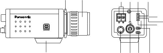
MAJOR OPERATING CONTROLS AND THEIR FUNCTIONS
w |
e |
r !0t |
y |
|
|
|
|||
|
|
DC 12V IN |
|
|
GP- KR222 |
|
OFF |
AGC ON |
u |
|
ELC |
ALC |
||
|
OFF |
ATW ON |
||
|
|
SOFT |
SHARP |
|
|
|
OFF |
BLC ON |
i |
|
|
POWER (AWC) |
|
|
|
|
|
|
|
|
|
S VIDEO OUT |
|
o |
|
|
VIDEO OUT |
|
|
|
|
R |
B |
|
|
|
|
VIDEO |
|
|
|
|
LEVEL |
|
|
|
L |
H |
|
q |
!4 !3!2 !1 |
-4-
1.Camera Mounting Screw Hole
This threaded hole (1/4” - 20) is used to mount the camera onto a mounting bracket or tripod.
2.Flange-back Adjusting Ring
This is used to adjust the back focal length or picture focus by rotating this ring to clockwise for C- mount lens or counterclockwise for special C- mount (CS mount) lens.
CAUTIONS :
1.Always set this ring to fully clockwise before mounting the lens to prevent damage of inner glass or CCD image sensor.
2.Do not turn this ring too much to counterclockwise when the C-mount lens is mounted as this could damage the inner glass or CCD image sensor.
3.Lens (Option)
4.12 V In Terminal (DC 12V IN)
This terminal accepts 12 V DC power source (10.8V - 16V)
5.AGC ON/OFF Switch (AGC ON/OFF)
This switch is used to select the gain of the video amplifier as follows :
ON: When the lens iris is fully opened at low light shooting, a clear picture is obtained by automatic increase of the gain.
OFF: A natural and low-noise picture is obtained under a low light condition.
6.Automatic Light Control/Electronic Light Control Selection Switch (ELC / ALC)
This switch is used to select the lens as follows. ALC: Choose this position when using an auto iris
lens.
ELC: Choose this position when using a fixed or manual iris lens.
7.Detail Level Selection Switch (SOFT/SHARP)
The detail/aperture level can be selected by this switch. Set this switch to the desired position while observing the picture on the monitor.
Note: The aperture is cut off at SOFT position.
-5-
8.Back Light Compensation On/Off Switch (BLC ON/OFF)
When back light affects the picture, set this switch to the ON position for a clear picture.
9.Automatic Tracing White Balance Control On/Off Switch (ATW, ON/OFF(AWC))
The white balance setting can be selected as ; ON: The white balance is automatically and con-
tinuously set by detecting the characteristic / colour temperature of light source through the lens and controlling the gain of red and blue signal even if the characteristic / colour temperature varies.
Note: The white balance setting is effected by the setting level of the ATW Control (11). (The bluish white is obtained when the ATW Control has been set to the B side.
OFF: The white balance is automatically set and fixed with the condition switched to the AWC from ATW. When the characteristic/colour temperature of light source changes, set this switch to the ATW ON position then set it back OFF.
Note: The white balance setting is effected by the setting level of the ATW Control (11). (The bluish white is obtained when the ATW Control has been set to the B side.
10.Power Indicator (POWER)
11.ATW Control (ATW ON, R/B)
This control adjusts the level of red and blue colour balance even if the ATW ON/OFF Switch (9) is set to any position. It is preset at the centre position which usually provides accurate colour reproduction.
12.Video Level Control (VIDEO LEVEL, L/H)
This control adjusts the level of auto iris control when the ELC/ALC Selection switch (6) is set to the ALC position, or the level of electric light control when the selection switch (6) is set to the ELC position.
Note: This control does not work in the following conditions
•AGC ON/OFF Switch (5) is set to OFF with the manual or fixed lens.
•AGC gain reaches the maximum level when setting the AGC ON/OFF Switch (5) to ON.
13.S-Video Output Connector (S-VIDEO OUT)
The luminance (Y) and chroma (C) signals for monitor are provided at this connector.
14.Video Output Connector (VIDEO OUT)
A 1.0 Vp-p / 75 ohms composite video signal is provided at this connector.
-6-

ELC (Electronic Light Control)/BLC (Back Light
Compensation) Description
1.ELC (Electronic Light Control)
In this mode a continuously variable electronic shutter is employed to automatically control exposure times in the CCD Image Sensor, according to the incoming light level. When this mode is selected, fixed or manual iris lens can be used instead of an ALC type lens.
Caution :
1.Under bright conditions such as outdoors, use an ALC type lens as the ELC control range is not wide enough under these conditions.
2.Under certain unique lighting conditions, the following may appear :
•strong smear and/or blooming on high light objects such as spot lights or windows.
•noticeable flicker in the picture and/or the colour rendition variations.
•periodic variance of white balance
Should these phenomena occur, use an ALC lens.
2. BLC (Back Light Compensation)
ON |
OFF |
When strong, unwanted background lighting interferes with the clarity of important scene objects, turn the Back Light Compensation On/Off Switch
(8) to the “ON” position.
Caution :
Setting this switch to the “BLC OFF” position is recommended in the use with the pan/tilt head or in the object having the rapid change illumination since the speed of lens iris becomes slow in the “BLC ON” position.
-7-

CONNECTION
1.A power supply of 12V DC is required.
2.Connect the power cable to the 12V DC Power Terminal on the rear panel of the camera.
−+
12 VDC
(10.5 V - 16 V)
Resistance of copper wire [at 20°C (68°F)]
Copper wire |
#24 |
#22 |
#20 |
#18 |
size (AWG) |
(0.22mm2) |
(0.33mm2) |
(0.52mm2) |
(0.83mm2) |
|
|
|
|
|
Resistance |
0.257 |
0.165 |
0.099 |
0.059 |
ohms/ft |
|
|
|
|
|
|
|
|
|
Resistance |
0.078 |
0.050 |
0.030 |
0.018 |
ohms/m |
|
|
|
|
•Calculation method of maximum cable length between camera and power supply.
10.5V DC ≤ VA − (R x 0.42 x L) ≤ 16V DC
L : Cable length (meter)
R : Resistance of copper wire (ohms/meter)
VA : DC output voltage of power supply unit
L standard = |
|
|
VA − |
12 |
|
|
(meter) |
|
|
|
|
|
|
||
|
|
|
|
||||
|
|
|
0.42 x R |
||||
L minimum = |
|
VA − |
16 |
|
|
(meter) |
|
|
|
|
|
|
|||
|
|
|
|
||||
|
|
|
0.42 x R |
||||
L maximum = |
VA − |
10.5 |
|
|
(meter) |
||
|
|
|
|
||||
|
|
|
|
||||
0.42 x R
-8-
Video Cable
1.It is recommended to use a video monitor whose resolution is at least equal to the camera's.
2.Terminate the camera output with 75-ohm resistor at the furthest end of its cable run.
A.It is recommended to use 75-ohms coaxial cable.
(RG-59/U, RG-6/U, RG-11/U, RG-15/U)
Monitor Monitor
B.Always set the last monitor`s termination switch to 75 ohms, and set the termination switches of intermediate monitors to high impedance (Hi-Z) position.
C.The maximum extensible coaxial cable length between the camera and the monitor is shown in the table 1. Since cable quality varies among manufactures, verify video quality before final installation if maximum length are to be used.
Table 1
Type of |
|
RG-59/U |
RG-6U |
RG-11/U |
RG-15/U |
coaxial cable |
|
(3C-2V) |
(5C-2V) |
(7C-2V) |
(10C-2V) |
|
|
|
|
|
|
Recommended |
(ft) |
825 |
1,650 |
1,980 |
2,640 |
maximum |
|
|
|
|
|
|
|
|
|
|
|
cable length |
(m) |
250 |
500 |
600 |
800 |
|
|
|
|
|
|
3. Wiring precautions :
•Do not bend coaxial cable into a curve whose radius is smaller than 10 times the cables diameter.
•Never staple the cable - not even with circular staples. Mismatching will occur.
•Never crush or pinch the cable
All of these will change the impedance of the cable and cause poor picture quality.
-9-
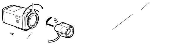
MOUNTING THE LENS
(1)Mount the lens by turning it clockwise onto the lens mount of the camera.
(2)Connect the lens cable to the Auto Iris Lens Connector on the camera when an auto iris lens is used.
Screw
1
2
Flange-back
Adjusting Ring
Caution: Always set the Flange-back adjusting ring to fully clockwise (C-mount side) by loosing the screw on the ring before mounting the lens otherwise the inner glass and CCD image sensor could be damaged by the lens.
FLANGE-BACK FOCAL LENGTH ADJUSTMENT
The following adjustment should be made by qualified service personnel or system installers.
When the flange-back focal length should be changed, the following adjustment is necessary.
Focus adjust for
C-mount lens
Focus adjust for
CS-mount lens
-10-
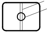
PREVENTION OF BLOOMING AND SMEAR
When the camera is aimed towards spotlights or other bright lights or light reflecting objects, smear or blooming may appear. Therefore the camera should be operated carefully in the vicinity of extremely bright objects to avoid smear or blooming.
If the camera is aimed at the sun or very bright light, such as laser beam, for a long period of time, the CCD image sensor may be burned in and blemishes (white or black dots) appears on the picture
Smear
Bright object
-11-
 Loading...