


fv-36rcql1

Operating and Installation Instructions
Mode d'emploi et notice d'installation
Instrucciones de uso e instalación
Range Hood
Hotte de cuisine
Campana de cocina
Model No.
Modèle
Nº de modelo
FV-36RLQL1
ENGLISHFRANÇAISESPAÑOL
READ AND SAVE THESE INSTRUCTIONS
Thank you for purchasing this Panasonic product.
Please read these instructions carefully before attempting to install, operate or service
the Panasonic product. Please carefully read the “GENERAL SAFETY INFORMATION”
Failure to comply with instructions could result in personal injury or property damage.
Please explain to users how to operate and maintain the product after installation, and
this booklet should be presented to users.
Please retain this booklet for future reference.
LIRE ET CONSERVER CE DOCUMENT
Nous vous remercions d'avoir acheté ce produit Panasonic. Veuillez lire attentivement
ces instructions avant d’essayer d’installer, d’utiliser ou de réparer ce produit Panasonic.
Veuillez également lire attentivement la section “CONSIGNES DE SÉCURITÉ” .
Le non-respect des instructions peut entraîner un risque de blessure corporelle et
de dommages matériels. Veuillez expliquer aux utilisateurs comment utiliser et eectuer
l’entretien de ce produit après l’installation et leur présenter ce document.
Conservez ce document pour référence ultérieure.
LEA Y CONSERVE ESTAS INSTRUCCIONES
Gracias por comprar este producto Panasonic. Lea atentamente estas instrucciones antes
de instalar, utilizar o mantener este producto Panasonic. Lea atentamente el capítulo
“INFORMACIÓN GENERAL SOBRE SEGURIDAD”. El incumplimiento de las instrucciones
podría causar daños personales o materiales. Explique a los usuarios cómo utilizar y
mantener el producto después de la instalación. Se recomienda ofrecer este manual a los
usuarios. Conserve este manual para consultas futuras.

CONTENTS
GENERAL SAFETY INFORMATION .................................................................................................................................................................. 3
SUPPLIED ACCESSORIES ................................................................................................................................................................................... 7
OPERATION ............................................................................................................................................................................................................ 8
MAINTENANCE ..................................................................................................................................................................................................... 9
DIMENSIONS ....................................................................................................................................................................................................... 10
WIRING DIAGRAM ............................................................................................................................................................................................11
SPECIFICATIONS ................................................................................................................................................................................................. 11
INSTALLATION ..................................................................................................................................................................................................... 12
PRODUCT SERVICE ........................................................................................................................................................................................... 20
2
GENERAL SAFETY INFORMATION
For Your Safety
To reduce the risk of injury, loss of life, electric shock, re, malfunction, and damage to
equipment or property, always observe the following safety precautions.
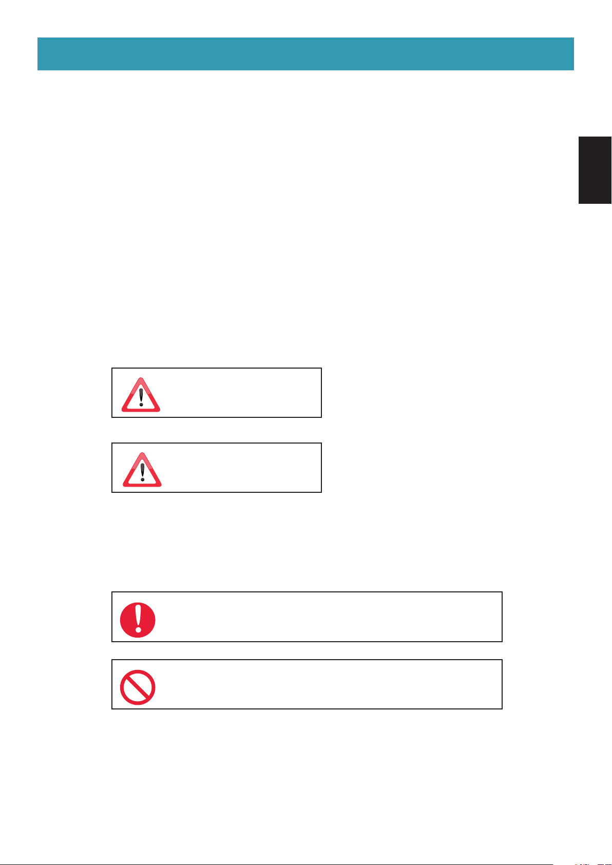
Explanation of symbol word panels
The following symbol word panels are used to classify and describe the level of hazard,
injury, and property damage caused when the denotation is disregarded and improper use
is performed.
Denotes a potential hazard that could
result in serious injury or death.
WARNING
Denotes a hazard that could result in
minor injury.
CAUTION
ENGLISH
The following symbols are used to classify and describe the type of instructions to be
observed.
This symbol is used to alert users to a specic operating procedure that
must be followed in order to operate the unit safely.
This symbol is used to alert users to a specic operating procedure that
must not be performed.
3
WARNING
TO REDUCE THE RISK OF A RANGE TOP GREASE FIRE:
a) Never leave surface units unattended at high settings. Boilovers cause smoking and greasy spillovers that may
ignite. Heat oils slowly on low or medium settings.
b) Always turn hood ON when cooking at high heat.
c) Clean ventilating fans frequently. Grease should not be allowed to accumulate on fan or lter.
d) Use proper pan size. Always use cookware appropriate for the size of the surface element.
TO REDUCE THE RISK OF INJURY TO PERSONS IN THE EVENT OF A RANGE
TOP GREASE FIRE, OBSERVE THE FOLLOWING:
a) SMOTHER FLAMES with a close-tting lid, cookie sheet, or metal tray, then turn o the burner. BE CAREFUL TO
PREVENT BURNS. If the ames do not go out immediately, EVACUATE AND CALL THE FIRE DEPARTMENT.
b) NEVER PICK UP A FLAMING PAN – You may be burned.
c) DO NOT USE WATER, including wet dishcloths or towels – a violent steam explosion will result.
d) Use an extinguisher ONLY if:
1) You know you have a Class ABC extinguisher, and you already know how to operate it.
2) The re is small and contained in the area where it started.
3) The re department is being called.
4) You can ght the re with your back to an exit.
Based on “ Kitchen Firesafety Tips ” published by NFPA.
TO REDUCE THE RISK OF FIRE, ELECTRIC SHOCK, OR INJURY TO PERSONS,
OBSERVE THE FOLLOWING:
a) Use this unit only in the manner intended by the manufacturer. If you have questions, contact the manufacturer.
b) Before servicing or cleaning unit, switch power o at service panel and lock the service disconnecting means to
prevent power from being switched on accidentally. When the service disconnecting means cannot be locked,
securely fasten a prominent warning device, such as a tag, to the service panel.
GROUNDING INSTRUCTIONS
a) This appliance must be grounded. In the event of an electrical short circuit, grounding reduces the risk of electric
shock by providing an escape wire for the electric current. This appliance is equipped with a cord having a grounding
wire with a grounding plug. The plug must be plugged into an outlet that is properly installed and grounded.
b) Improper grounding can result in a risk of electric shock.
c) Consult a qualied electrician if the grounding instructions are not completely understood, or if doubt exists as
to whether the appliance is properly grounded.
d) Do not use an extension cord. If the power supply cord is too short, have a qualied electrician install an outlet
near the appliance.
4

WARNING
TO REDUCE THE RISK OF FIRE, ELECTRIC SHOCK, OR INJURY TO PERSONS,
OBSERVE THE FOLLOWING:
a) Installation work and electrical wiring must be done by qualied person(s) in accordance with all applicable
codes and standards, including re-rated construction.
b) Sucient air is needed for proper combustion and exhausting of gases through the ue (chimney) of fuel
burning equipment to prevent back drafting. Follow the heating equipment manufacturer’s guideline and safety
standards such as those published by the National Fire Protection Association (NFPA), and the American Society
for Heating, Refrigeration and Air Conditioning Engineers (ASHRAE), and the local code authorities.
c) When cutting or drilling into wall or ceiling, do not damage electrical wiring and other hidden utilities.
d) Ducted fans must always be vented to the outdoors.
- Clean the lters and all laden surfaces on a regular basis.
- To provide protection against electric shock, connect to properly grounded outlets only.
- To reduce the risk of re, use only metal ductwork.
-
Stop using the unit when any abnormality / failure occurs and turn “OFF” the power switch or pull out the 3 pin plug.
Example of abnormality failure:
- Abnormal noise or heat.
- Abnormal emission of smell / smoke.
- Fire or oil ignition.
- Insert the Power Plug rmly, otherwise it may cause re or electric shock.
- The supply cord must be set properly not to be damaged. The manufacturer declines all liability if the safety
standards are not observed.
- The socket used to connect the installed equipment to the electrical power supply must be within reach:
otherwise, install a mains switch to disconnect the Range Hood when required.
- The wall plugs must have a secure grip.
- The enclosed screws and wall plugs are suitable for solid brickwork or solid concrete. Suitable fasteners must be
used for other structures (e.g. plasterboard, porous concrete, porous bricks).
- The maximum length of the ue fastening screws (supplied by the manufacturer) must be 0
Use of non-compliant screws with these instructions can lead to danger of an electrical nature.
- Keep in mind that installations with dierent types of fastening systems from those supplied, or which are not
compliant, can cause electrical and mechanical seal danger.
- Clean the Power Plug regularly with dry cloth, otherwise it may cause insucient insulation due to moisture, and
may cause re.
- There is a re risk if cleaning is not carried out in accordance with the instructions.
- Accessible parts may become hot when used with cooking appliances.
- Always supervise the cooking process during the use of deep-fryers:
Overheated oil can catch re.
- A statement to the eect that when the product is to no longer be used, it must not be left in place but remove,
to prevent it from possibly failing.
- Always check that all the electrical parts (lights, exhaust device), are o when the appliance is not being used.
- This appliance is not intended for use by young children or inrm persons unless they have been adequately
supervised by a responsible person to ensure that they can use the appliance safely. Young children should be
supervised to ensure they do not play with the appliance.
- To reduce the risk of re or electric shock, do not use this fan with any solid-state speed control device.
- Do not connect the appliance to ues (from boilers, replaces, etc.).
- Do not discard the packaging or any part of it, or leave it unattended.
It can constitute a suocation hazard for children, especially the plastic bags.
- Do not ambé under the Range Hood.
- Never cook on “open” ames under the Range Hood.
- Do not leave open, unattended ames under the Range Hood.
-
Do not switch “OFF” or “ON” the Range Hood when there may be a gas leak in your gas hob. Gas explosion may result in.
- Do not handle the Power Plug with wet hand, otherwise it may cause electric shock.
- Do not disassemble the unit for reconstruction.
33
/64"
(13mm).
ENGLISH
5

CAUTION
- Use the neutral detergent only.
- For residential use only.
- The minimum distance between supporting surface for the cooking vessels on the hob and lowest part of the Range Hood
must be at least 25 9⁄16" (650 mm).
- To reduce risk of re and to properly exhaust air, be sure to duct air outside.
- Before the appliance is put into operation, all the protective lm must be removed.
- Check whether the Range Hood is installed securely and horizontally.
- Always operate the Range Hood when using gas cooker.
- Avoid parts from falling when detaching it for cleaning.
- Ensure that the wires inside the Range Hood are not disconnected or cut:
in the event of damage, contact your nearest Servicing Department.
- When disconnect the Power Plug, hold the plug itself. Do not pull the cord anyway.
The cord may be damaged, it may cause re or electric shock.
- Be sure to disconnect the Power Plug from the wall outlet or switch o the breaker when not using for a long time.
- Product must be installed on the ceiling, which is strong enough to hold the unit. Reinforce it if necessary.
- The Range Hood should be installed so that the metal part of the product and mounting screw do not contact with any metalic item
inside the wall, such as metal laths, wire laths and metal plate, it is possible to cause re harzards in case of electrical leak.
- During installation, always use personal protective equipment (e.g.: Safety shoes, gloves) and adopt prudent and proper conduct.
- Please wear gloves during the cleaning work.
- Make sure that the electric service supply voltage is AC 120 V, 60 Hz.
- Protect the supply wiring from sharp edges, oil, grease, hot surfaces, chemicals or other objects.
- Suitable for use in a household cooking zone.
- Before installing the Range Hood, check the integrity and function of each part.
Should anomalies be noted, do not proceed with installation and contact the Dealer.
- Do not vent exhaust air into spaces within walls or ceilings or into attics, crawl spaces, or garages.
- For general ventilating use only. Do not use to exhaust hazardous or explosive materials and vapors.
- It is dangerous to modify or attempt to modify the characteristics of this system.
In the event of malfunctions or if repairs are required to the appliance, do not attempt to solve the problems directly. Repairs
performed by unqualied persons may cause damage. For all repair and other work on the appliance, contact the service centre.
- Insist on original spare parts.
- Do not insert pointed metal objects (cultery or utensils) into any aperture in the Range Hood.
- Do not use a steam cleaner for cleaning the appliance. The steam could reach the electronics, damaging them and causing
short-circuits.
- Do not use too much moisture or water around the push button control panel and lighting devices in order to prevent humidity
from reaching electronic parts.
- Do not clean electrical parts, or parts related to the motor inside the Range Hood, with liquids or solvents.
- Never use petrol, benzene, thinner or any other similar chemicals to clean the product.
- Do not use abrasive products.
- Do not carry out any cleaning operations when parts of the Range Hood are still hot.
- Never use the product in a wet place. It may cause re or failure.
- During operation, never insert ngers or other objects into any aperture in the Range Hood. Failure or injury may result in.
- Do not put anything on the Range Hood. It may cause re, failure or injury.
- Do not kink the supply wiring.
- Never use the Range Hood without the metal lters:
in this case, grease and dirt will deposit in the equipment and compromise its operation.
6
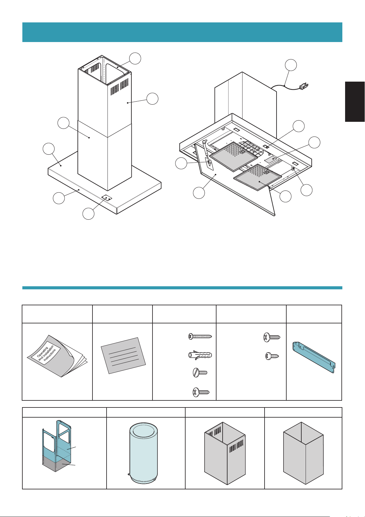
SUPPLIED ACCESSORIES
Part identication :
3
4
1
12
2
ENGLISH
6
11
8
5
1 - Trellis
2 - Extension
3 - Chimney
4 - Range Hood body
5 - Electronic push button control panel
6 - LED spotlight illumination x 6
Supplied accessories :
A - Operating and
installation instructions
13
B - Warranty sheet C - Screw pack 1 D - Screw pack 2 E - Extension
Warranty sheet
7
7 - Perimeter suction panel
8 - Piston bar
9 - Magnet x 2
10 - Metal lter x 2
11 - Name plate
12 - Power cord
13 - Module support for add-on Module that provides additional
features (Module sold separately)
Ø5 x 50 mm (4 pcs)
Ø8 wall plug (4 pcs)
Ø4 x 7 mm (4 pcs)
Ø4.2 x 12.5 mm (9 pcs)
Ø3.9 x 9.5 mm (8 pcs)
10
9
support element
1 pc 2 pcs
Ø4.2 x 12.5 mm (2 pcs)
F - Trellis G - Pipe H - Extension I - Chimney
Trellis
(1pc)
Element
(1pc)
Screws xing element
Ø4 x 9 mm (8 pcs)
Wall plugs are for solid brickwork or solid concrete.
1 pc
1 pc
1 pc
2 pc
7

OPERATION
1
2
3
1
212
1
2
3
Key No.
1 2 3 4 5 6
Key 1 : [ Function ] Filter alarm / Timer
The BLUE lighting indicates that the metal lter alarm is active (after 30 hours); to deactivate this alarm and
reset the hour meter, press the button for 3 seconds.
The BLUE blinking indicates that the timer function is active. This function can be activated only if the motor
is already active with any speed when the key is pressed. This function activates the auto power o function
of the Range Hood after 15 minutes. The Range Hood can be turned o by the user and the function will be
disabled.
Key 2 : [ Function ] On (1st Speed) / O motor / 24 hours function
Press the key to select the 1st speed (the BLUE lighting).
When the 1st speed is on and the key is pressed, both the LED and MOTOR will turn o.
If the motor is active with any speed, to turn o the Range Hood, press key 2 twice.
When the LED is o, if the key is pressed for at least 3 sec, the 24 hours function activates.
During the 24 hours function (which lasts 24 hours), the LED blinks.
From the activation of this function, the Range Hood will remain active for 1 hour at 1st speed, then it will stop
for 3 hours and reactivate for another hour. These cycles are repeated until timeout. With activation of this
function, other speeds may not be selected. To deactivate this function, keep key 2 pressed for at least 3 seconds.
Key 3 : 2nd Speed
If the LED is o and another speed is active, press the key to select the 2nd speed (the BLUE lighting) and turn
the LED associated to the previously selected speed o.
If the LED is o and no speed is active, the key is disabled.
When the LED is on, key 3 is disabled.
To turn o the Range Hood, press key 2 twice.
Key 4 : 3rd Speed
If the LED is o and another speed is active, press the key to select the 3rd speed (the BLUE lighting) and turn
the LED associated to the previously selected speed o.
If the LED is o and no speed is active, the key is disabled.
When the LED is on, key 4 is disabled.
To turn o the Range Hood, press the key 2 twice.
Key 5 : 4th Speed (BLUE blinking)
If the LED is o and another speed is active, press the key to select the 4th speed (the BLUE blinking) and turn
the LED associated to the previously selected speed o.
If the LED is o and no speed is active, the key is disabled.
When the LED is on, key 5 is disabled.
The fourth speed lasts 7 minutes, then the Range Hood changes to the third speed.
To turn o the Range Hood, press key 2 twice.
Key 6 : Light
Light : Pressing key 6 will turn the light on and o. The BLUE lighting if the light is on.
8

MAINTENANCE
WARNING
Before servicing or cleaning unit, switch power o at service panel and lock the service
disconnecting means to prevent power from being switched on accidentally.
When the service disconnecting means cannot be locked, securely fasten a prominent
warning device, such as a tag, to the service panel.
CAUTION
Regular maintenance guarantees proper operation and performance over time.
Special attention is to be paid to the metal lters : frequent cleaning of the metal lters and their supports ensures that no
ammable grease is accumulated.
CLEANING OF EXTERNAL SURFACES
You are advised to clean the external surfaces of the Range Hood at least once every 15 days to prevent oily substances and
grease from sticking to them.
Alternatively and for all the other types of surfaces, it can be cleaned using a damp cloth, slightly moistened with mild,
liquid detergent or denatured alcohol.
Complete cleaning by rinsing well and drying with soft cloths.
Do not use products that contain abrasive substances or cloths NOT specically designed for cleaning steel.
The glass panels can only be cleaned with specic, non-corrosive or non-abrasive detergents using a soft cloth.
The Manufacturer declines all responsibility for failure to comply with these instructions.
CAUTION
CLEANING OF INTERNAL SURFACES
Do not clean electrical parts, or parts related to the motor inside the Range Hood, with liquids or solvents.
METAL FILTERS
It is advised to frequently wash the metal lters (at least once a month) leaving them to soak in boiling water and cleaning
solution for 1 hour, taking care not to bend them.
- Do not use corrosive, acid or alkaline detergents.
- Rinse them well and wait for them to be completely dry before reassembling them.
- Washing in a dishwasher is permitted, however, it may cause the metal lter material to darken : to reduce the possibility of
this problem from happening, use low-temperature washes (131 °F/ 55 °C max.).
To remove the perimeter suction panel and the metal lters as shown gure below.
Please wear gloves during the cleaning work.
Be careful when removing the perimeter suction panel in case oil has accumulated on it and
may fall out.
ENGLISH
How to remove of the
metal lters
How to remove of
the perimeter suction
panel
1
1
Piston bar
2
Pin
Please slowly remove the pin
while supporting it with ngers
so that it will not fall.
2
3
4
3
5
6
Be sure to check that the pin is attached to the piston bar to
reassemble the perimeter suction panel. If not attached, the
perimeter suction panel cannot be supported at the specied
position.
9
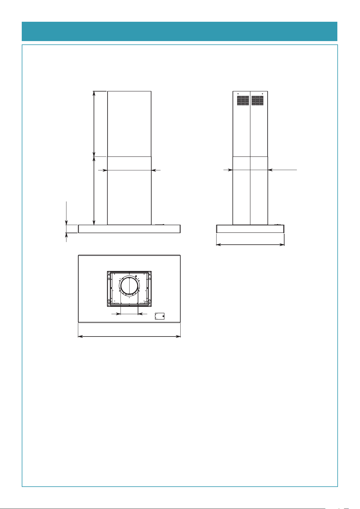
DIMENSIONS
FV-36RLQL1
574 mm
max. 22 5/8"
max.
23 9/16"
600 mm
15 1/4"
387 mm
12 3/16"
310 mm
2 3/4"
70 mm
23 7/16"
596 mm
Ø5 7/8"
Ø150 mm
35 3/8"
900 mm
10
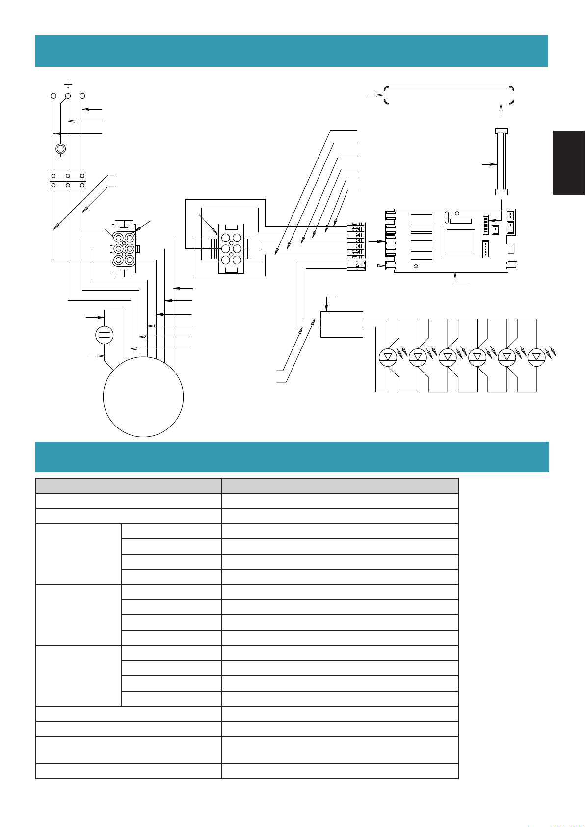
WIRING DIAGRAM
NL
WHITE
GREEN
BLACK
BROWN
BLUE
CONTROL PANEL
WHITE (2° SPEED)
ORANGE (4° SPEED)
GRAY (LINE)
RED (NEUTRAL)
BLACK (3° SPEED)
BLUE (1° SPEED)
5 V
FLAT CABLE
ENGLISH
PIN
REAR VIEW
1
2
3
WHITE (2° SPEED)
BLUE (1° SPEED)
GRAY (3° SPEED)
BLACK (4° SPEED)
RED
YELLOW - GREEN
4
5
6
TRANSFORMER
12 V
BROWN
BLUE
LED LIGHT SPOT
BROWN
YELLOW
REAR VIEW
4
5
6
PIN
1
2
3
M
~
SPECIFICATIONS
Model No. FV-36RLQL1
Voltage AC 120V
Frequency 60 Hz
4th Speed 328
Power (W)
Air Volume
at 0.1" WG
(CFM)
Noise (sones)
Lamp 1.2 W x 6
Pipe Diameter Ø8" ( Ø203 mm )
Dimension (L x W x H) 35 3/8" x 23 7/16" x 26 3/8"
Weight 115 lb. (52 kg)
3rd Speed 226
2nd Speed 180
1st Speed 137
4th Speed 440
3rd Speed 340
2nd Speed 240
1st Speed 130
4th Speed 4.0
3rd Speed 2.0
2nd Speed 0.9
1st Speed <0.3
( 900 mm x 596 mm x 670 mm )
MAIN BOARD
HVI Certied performance based on HVI Procedures 915, 916, and 920.
11

INSTALLATION
Before installing the Range Hood, carefully read chap. "GENERAL SAFETY INFORMATION".
Installation preparation
- Measure the height H from the hob to the ceiling and identify the height Y, taking into consideration the minimum
distance X, between the bottom of the Range hood and the hob.
- Determine the installation method by the height Y.
- Install reinforcement wooden frames to hold the Range Hood.
【 Installation with trellis and element 】
Reinforcement
wooden frame
CEILING
Trellis
Element
X
min. 25 9/16”
min. 650 mm
Reinforcement
wooden frame
Y
min. 29 1/4” - max. 46 7/32”
min. 743 mm - max. 1174 mm
H
【
Installation with element and extension
support element 】
Reinforcement
wooden frame
CEILING
Extension support
element
Element
X
min. 25 9/16”
min. 650 mm
Y
26 3/8”
670 mm
H
12
Reinforcement wooden frame structure
Reinforcement
wooden frame
9 5/8”
245 mm
Screw position
Range
Hood
outline
Screw position Screw position
13 7/8” - 353 mm
( Top View )
Reinforcement wooden frame structure
Joist Joist
Joist
Reinforcement
wooden frame
9 5/8”
245 mm
Screw position
Range
Hood
outline
13 7/8” - 353 mm
( Top View )
Joist

Phase 1 (Fig. A)
1
2
3
4
5
1
2
3
4
- Refer to Chap. "MAINTENANCE", remove the perimeter suction panel and the metal lters completely.
- Remove the front panel (A) (Fig. , ).
- Disconnect the LED connectors (Fig. ) and the motor connector (B) (Fig. ).
And then, pull out the motor connector (B) from the loop of the cable tie (Fig. ).
A
4
ENGLISH
B
2
5
2
3
Cable tie
A
LED
connector
x3
1
x3
(Fig. B)
- Loosen the 4 screws securing the motor chamber (C) (Fig. ).
- Shift the motor chamber (C) sideways to position the 4 screws against the hole instead of the slot (Fig. , ).
- Lift the motor chamber (C) upwards to remove it from the Range Hood body (Fig. ).
B
B
4
C
1
2
3
13
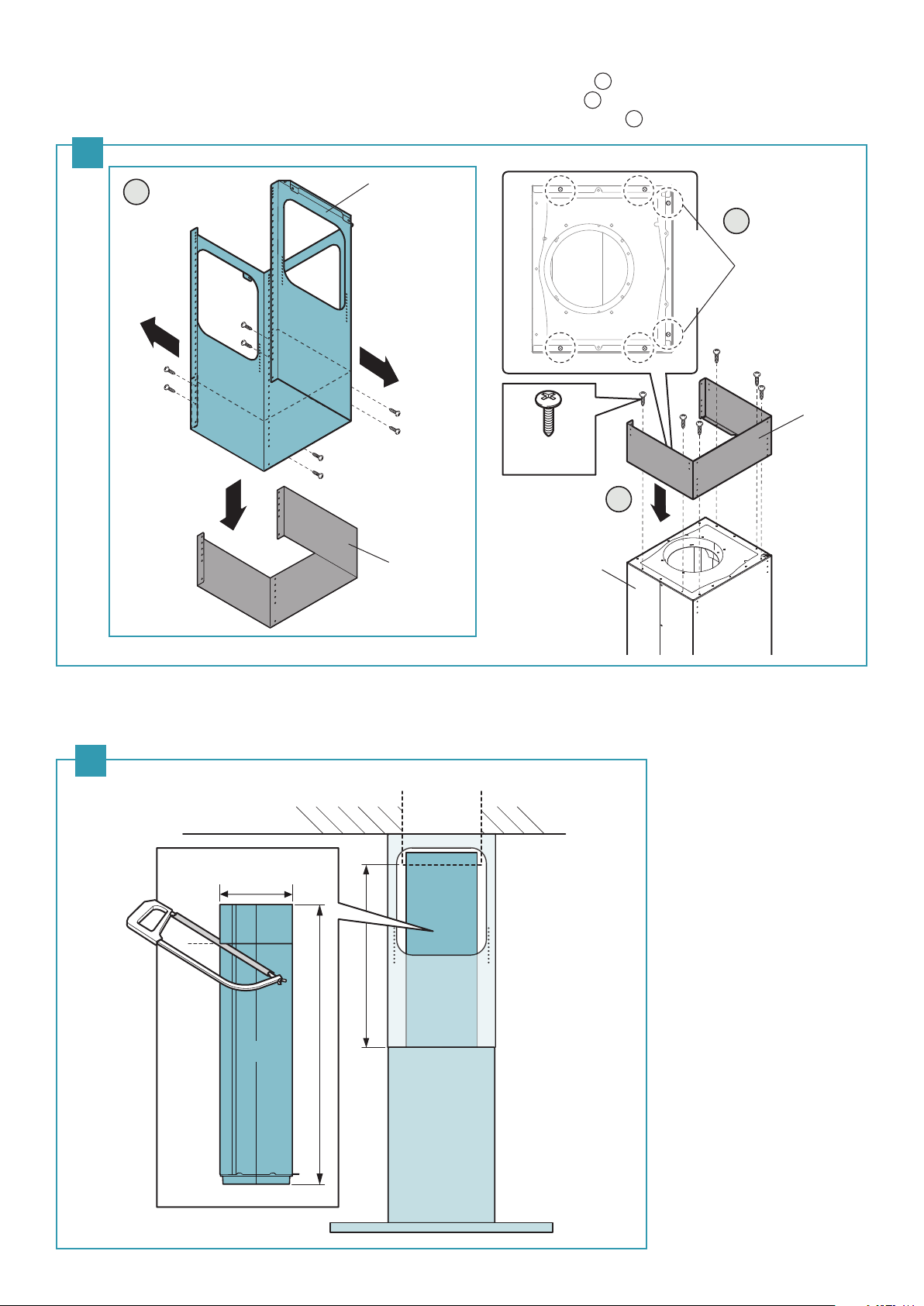
(Fig. C)
1
2
3
- Unfasten 8 screws (V1 Ø3.9×9) and remove the element (D) from the trellis (E) (Fig. ).
- Unfasten 2 screws (V2 Ø4.2×12.5) xed to the top of the motor chamber (C) (Fig. ) before xing the element (D).
Fasten the element (D) to the motor chamber (C) with the 6 screws (V2 Ø4.2×12.5) (Fig. ).
C
1
E
2
Before xing the
element, unfasten
(Front side)
2 screws
(Ø4.2×12.5)
D
V1
8 - Ø3.9×9
Keep screws to
x trellis and
element when
installed
D
V2
6 - Ø4.2×12.5
3
C
(Front side)
(Fig. D)
- Measure the height “F” as indicated in Figure D.
- Cut the pipe (G) to required length, so that the pipe (G) is installed perfectly vertical.
D
CEILING
Ø 8”
Ø 203 mm
G
F
G
28”- 711 mm
14

(Fig. E)
1
B
2
B
1
A
- Carefully insert the pipe (G) in the motor tting (H) of the motor chamber (C) and fasten it with 3 screws (V3 Ø4.2×12.5).
E
G
V3
3 - Ø4.2×12.5
(Front side)
C
H
ENGLISH
(Fig. F)
[ Installation with trellis and element ]
- Fasten the trellis (E) to the ceiling using the 4 screws (V4 Ø5×50) (Fig. ).
[ Installation with element and extension support element ]
- Fasten the extension support elements (J) to the element (D) with 8 screws (V5 Ø3.9×9.5) (Fig. ) and fasten the motor
chamber (C) to the ceiling using the 4 screws (V4 Ø5×50) (Fig. ).
F
【 Installation with trellis and
element 】
Reinforcement wooden frame
Joist
Joist
Ceiling
【
Installation with element and extension
1A 1B
D
J
support element 】
Reinforcement wooden frame
Joist
J
Ceiling
Joist
V5
8 – Ø3.9×9.5
(Front side)
C
2B
V4
4 - Ø5×50
(Front side)
E
V4
4 - Ø5×50
15

(Fig. G)
1
3
2
[ Installation with trellis and element ]
- Slide the motor chamber (C) on the trellis (E) until reaching to the desired height (K) (Fig. ).
- Secure the motor chamber (C) with the 8 self-threading screws (V1 Ø3.9×9) (Fig. ).
- Connect the pipe (G) to the external exhaust (Fig. ).
G
3
E
K
G
1
(Front side)
CEILING
V1
8 - Ø3.9×9
2
C
Note :
- The exhaust conveyor that protrudes from the upper part of the Range Hood must be connected with the pipe that conducts
the fumes and vapours in an external output.
- The fumes and vapours are discharged outside through the exhaust pipe.
To this end, the Range Hood outlet tting must be connected via a pipe, to an external output.
- The diameter of the fume discharge duct must be no smaller than the Range Hood connection.
- The outlet pipe must have a diameter not less than that of the Range Hood tting.
- The outlet pipe must have :
• A slight slope downwards (drop) in the horizontal sections to prevent condensation from owing back into the motor.
• The duct must be installed not to bend it in the immediate vicinity of the discharge hole. Otherwise, the return valve will get
stuck with the duct, and will not work for the exhaust properly.
• Reduce curves to the bare minimum, and check that the length of the ducts is also the bare minimum.
• You are required to insulate the pipes if it passes through cold environments.
16
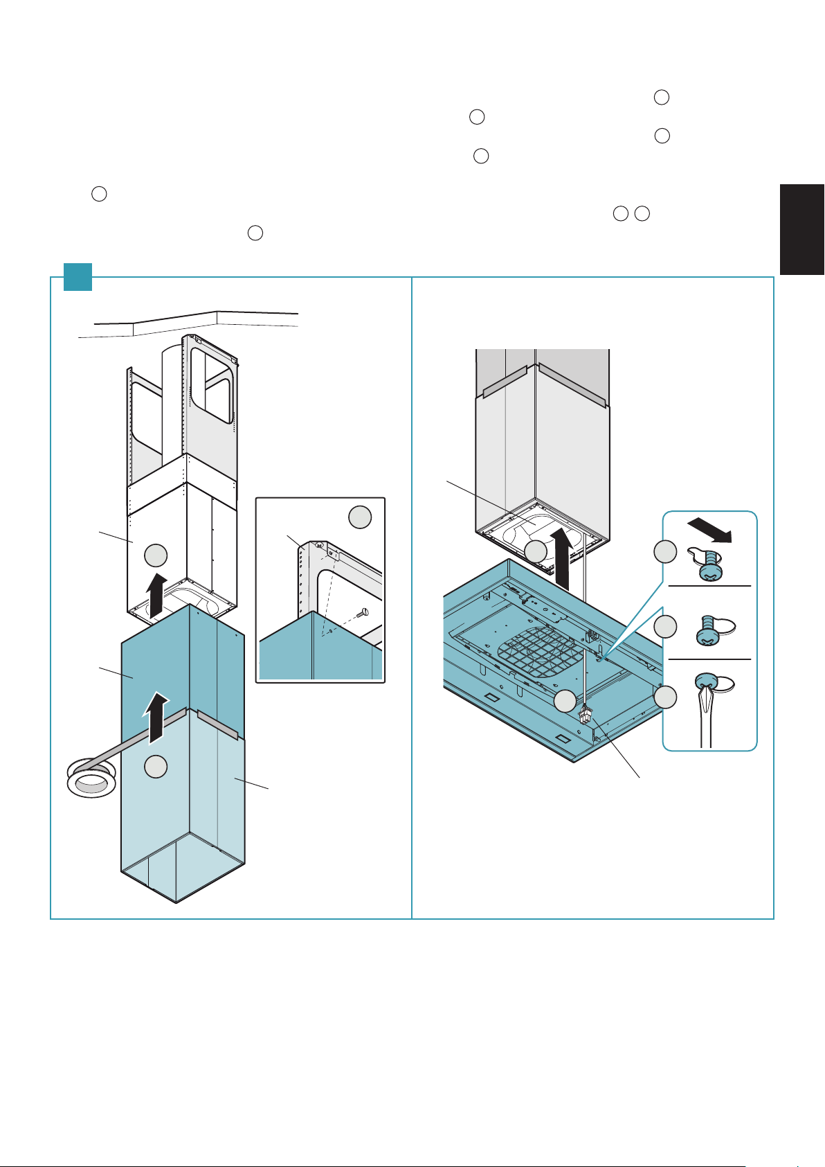
Phase 2 (Fig. H)
1
2
3
4
5
6
7
8
[ Installation with trellis and element ]
- Insert the chimney (L) onto the extension (M) and fasten them together with paper adhesive tape (Fig. ).
- Insert the chimney-extension set (L+M) in the motor chamber (C) (Fig. ).
- Fasten the chimney-extension set (L+M) onto the trellis (E) with the 4 metric screws M4 (V6 Ø4×7) (Fig. ).
- Pass the motor connector (B) through the hole of the Range Hood (Fig. ).
- Lift the Range Hood body so that its lower holes are centred on the 4 - M5 metrics screws of the motor chamber (C)
(Fig. ).
- Shift the motor chamber (C) sideways so that the metric screws are positioned on the slots (Fig. , ) and then
tighten them permanently (Fig. ).
H
ENGLISH
C
M
C
3
E
2
V6
4 – Ø4×7
1
L
5 6
4
B
7
8
17

(Fig. I)
4
3
6
5
1
2
[ Installation with element and extension support element ]
- Insert the chimney (L) on the motor chamber (C) (Fig. ).
- Pass the motor connector (B) through the hole of the Range Hood (Fig. ).
- Lift the Range Hood body so that its lower holes are centred on the 4 - M5 metrics screws of the motor chamber (C)
(Fig. ).
- Shift the motor chamber (C) sideways so that the metric screws are positioned on the slots (Fig. , ) and then
tighten them permanently (Fig. ).
I
J
C
1
L
3
2
4
5
6
B
18
 Loading...