


|
CONFIDENTIAL |
1 (44) |
|
NHM—2/5/6 |
Repairhints |
Customer Care Europe, Middle East & Africa |
3410 |
Version 4.0 Approved |
SCCE Training Group |
Date 20.11.2002 |
|
Repairhints
Service-Level 3 & 4
3310/3330/
3410
NHM-2/5/6
© NMP 2002
Checked by: |
Approved by: |
Customer Care E&A |
SCCE Training Group |

|
CONFIDENTIAL |
2 (44) |
|
NHM—2/5/6 |
Repairhints |
Customer Care Europe, Middle East & Africa |
3410 |
Version 4.0 Approved |
SCCE Training Group |
Date 20.11.2002 |
|
GENERAL
-How to use this document
Put the colored schematics behind this manual.
Now you are able to follow these specifications with graphical layouts and it is easier for you to find the components and measuring points.
-Component characteristics:
Some components contain important data.
Several described steps are only practicable if you are able to reflash/ realign the phone and/or rewrite IMEI/SIMlock in certain cases. Please pay attention to separate notes.
-Broken balls, µBGA
All replaceable µBGA-components must be renewed after removing. Reflow with hot air fan is strictly forbidden!
Check soldering points, remove oxidated solderings (broken balls) carefully by enclosing few new solder before placing new components.
µBGA must be soldered only with NMP approved µBGA-rework machines (e.g. Zevac/OK International). Only use recommended fluxtype and an appropriate amount of it.
-PCB handling & cleaning
To avoid damages of PCB and/or components through electrostatic discharging, handle the module in ESD-suitable cases only. Always wear ESD-bracelets, which must be connected to earth bonding point. Do not make any loose wiring connections or do some other unqualified rework anywhere.
For cleaning only use appropriate materials, do not use scratching or rubbing tools.
Because of organic surface protection (OSP) cleaning must only be done with a lint-free cloth, which may be moistened with DI-water. IPA or other solvent like ethanol should only be used to clean gold pads for spring contacts without affecting the surrounding copper layers.
-Realign after repair
Characteristics of replacement parts are different.
To prevent additional faults after repair (eg. low standby time, loosing network etc.) it is necessary to retune phone values after repair. But never try to cover a fault by tuning.
© NMP 2002
Checked by: |
Approved by: |
Customer Care E&A |
SCCE Training Group |

|
CONFIDENTIAL |
3 (44) |
|
NHM—2/5/6 |
Repairhints |
Customer Care Europe, Middle East & Africa |
3410 |
Version 4.0 Approved |
SCCE Training Group |
Date 20.11.2002 |
|
INTRODUCTION
IMPORTANT:
This document is intended for use by authorized NOKIA Service Centers only.
The purpose of this document is to provide some further service information for NOKIA 3310 / 3330/3410 phones. It contains a lot of collected tips and hints to find failures and repair solutions easily.
It also will give support to the inexperienced technicians.
Saving process time and improving the repair quality is the aim of using this document.
We have built it up based on fault symptoms (listed in "Contents") followed by detailed description for further analysis. It is to be used additionally to the service manual and other service information, e.g. Service Bulletins.
For that reason it does not contain any circuit descriptions or schematics.
All measurements are made by using following equipment:
Nokia repair SW |
: WinTesla Version 6.46/15.04.2002 |
DLL version |
: 311.15.00 / 26.06.2002 |
Nokia module jig |
: MJS -19 |
Digital multimeter |
: Fluke 73 |
Oscilloscope |
: Hitachi V-1565; Fluke PM 3380A/B |
Spectrum Analyzer |
: Advantest R3161 with an analogue probe |
RF-Generator / |
: Rohde & Schwarz CMU 200 |
GSM Tester |
|
While every endeavour has been made to ensure the accuracy of this document, some errors may exist. If the reader finds any errors, NOKIA should be notified in writing, using following procedure:
Please state:
Title of the Document + Issue Number/Date of publication.
Page(s) and/or Figure(s) in error.
Please send to: |
Nokia GmbH |
|
SCCE Training Group |
|
Customer Care E&A |
|
Meesmannstr.103 |
|
D-44807 Bochum / Germany |
|
Email: training.sace@nokia.com |
Copyright © Nokia Mobile Phones.
This material, including documentation and any related computer programs, is protected by copyright, controlled by Nokia Mobile Phones. All rights are reserved. Copying, including reproducing, modifying, storing, adapting or translating, any or all of this material requires the prior written consent of Nokia Mobile Phones. This material also contains confidential information, which may not be disclosed to others without the prior written consent of Nokia Mobile Phones.
© NMP 2002
Checked by: |
Approved by: |
Customer Care E&A |
SCCE Training Group |

|
CONFIDENTIAL |
4 (44) |
|
NHM—2/5/6 |
Repairhints |
Customer Care Europe, Middle East & Africa |
3410 |
Version 4.0 Approved |
SCCE Training Group |
Date 20.11.2002 |
|
Contents
PREFACE |
2 |
General |
2 |
Introduction |
3 |
List of flowcharts |
6 |
List of figures |
6 |
Important Information |
7 |
AM Suppression tuning |
8 |
CHAPTER 1 |
HW – CHANGES |
11 |
|
Difficulties when removing B-Cover (SB13 / NHM-5) |
11 |
|
Intermittent switch-off problem (SB 28 / NHM-5, SB 7 / NHM 6) |
11 |
|
Correct component replacement in UB4_ 10 or later of NHM-5 (SB053) and NHM-6 (SB31) |
12 |
|
HW Change description Overview of NHM-2/6 |
13 |
CHAPTER 2 |
CHANGING OF D301 |
14 |
|
|
|
Step by step description of changing the FLASH/EEPROM –combination D301 |
14-16 |
|
|
CHAPTER 3 |
PHONE DOES NOT SWITCH ON |
17-19 |
||
CHAPTER 4 |
FLASH UPDATE NOT POSSIBLE |
20 |
|
|
|
Failure message |
”MCU boot failure,serial clock-/data line failure” |
21 |
|
|
Failure message |
”Algorithm code fail / alias ID missing” |
21 |
|
|
Failure message |
”External RAM failure” |
21 |
|
CHAPTER 5 |
PHONE SWITCHES OFF INTERMITTENT |
22 |
|
|
CHAPTER 6 |
LOW STANDBY / OPERATION MODE TIME |
23 |
|
|
|
Low standby / operation time |
23-24 |
|
|
|
Off state current fail |
24 |
|
|
|
Sleep mode current fail |
24 |
|
|
CHAPTER 7 |
NOT CHARGING |
25 |
|
|
|
Not charging |
|
26 |
|
|
Nothing happens if charger is connected |
26 |
|
|
|
Display message “Not charging” |
26 |
|
|
|
Display message “Reconnect charger” |
|
|
|
© NMP 2002
Checked by: |
Approved by: |
Customer Care E&A |
SCCE Training Group |

|
CONFIDENTIAL |
5 (44) |
|
NHM—2/5/6 |
Repairhints |
Customer Care Europe, Middle East & Africa |
3410 |
Version 4.0 Approved |
SCCE Training Group |
Date 20.11.2002 |
|
CHAPTER 8 |
CONTACT SERVICE |
27 |
|
MCU ROM Checksum failed |
27 |
|
CCONT Interface failed |
27 |
|
COBBA parallel/serial failed |
27 |
|
DSP Alive test failed |
27 |
|
EEPROM sec/tune checksum failed |
27 |
CHAPTER 9 |
SIMCARD FAULTS |
28 |
|
Display message “Insert SIMcard” |
29 |
|
Display message ”SIMcard not accepted” |
29 |
CHAPTER 10 |
INTERNAL AUDIO FAULTS |
30 |
|
Speaker faulty |
30 |
|
Microphone does not work |
30 |
CHAPTER 11 |
USER INTERFACE FAULTY |
31 |
|
Display failure |
31 |
|
Keypad malfunction |
31 |
|
Backlight failure |
31 |
|
Vibra failure |
32 |
|
Buzzer failure |
32 |
|
Clock time problems |
32 |
CHAPTER 12 |
NO SERVICE |
33 |
|
No or too low TX power GSM 900 |
33-37 |
|
No or too low TX power GSM 1800 |
37 |
|
Faulty spectrum |
38 |
|
No RX-calibration GSM 900 possible |
39-42 |
|
No RX-calibration GSM 1800 possible |
42 |
|
Poor service or no network coverage, C508 faulty |
43 |
CHAPTER 13 |
CHANGE HISTORY |
44 |
© NMP 2002
Checked by: |
Approved by: |
Customer Care E&A |
SCCE Training Group |

|
CONFIDENTIAL |
6 (44) |
|
NHM—2/5/6 |
Repairhints |
Customer Care Europe, Middle East & Africa |
3410 |
Version 4.0 Approved |
SCCE Training Group |
Date 20.11.2002 |
|
List of flowcharts
Flowchart 3-1 |
Phone does not switch on |
Chapter 3 |
17 |
Flowchart 4-1 |
Flash update not possible |
Chapter 4 |
20 |
Flowchart 6-1 |
Low standby/Operation mode time |
Chapter 6 |
23 |
Flowchart 7-1 |
Not charging |
Chapter 7 |
25 |
Flowchart 9-1 |
SIMcard faults |
Chapter 9 |
28 |
Flowchart 10-1 |
Internal audio faults |
Chapter 10 |
30 |
Flowchart 12-1 |
No service (no TX) |
Chapter 12 |
33 |
Flowchart 12-2 |
No Rx calibration GSM 900 possible |
“ |
39 |
List of figures
Figure 1-1 |
D-Cover NHM-5 (the pin who is cut) |
Chapter 1 |
11 |
Figure 2-1 |
“Phone Identity Information” window in WinTesla |
Chapter 2 |
14 |
Figure 2-2 |
“Flash Menu Selection” window in WinTesla |
“ |
14 |
Figure 2-3 |
“Flash Phone” window in WinTesla |
“ |
15 |
Figure 2-4 |
Message after proceed “Flash Phone” window in WinTesla |
“ |
15 |
Figure 2-5 |
“Default Factory values” window in WinTesla |
“ |
16 |
Figure 2-6 |
Message after set ”Full Factory” on “Default Factory values” window |
“ |
16 |
Figure 2-7 |
“Production Data Edit” window in WinTesla |
“ |
16 |
Figure 3-1 |
32.768 kHz at C220 |
Chapter 3 |
18 |
Figure 3-2 |
13 MHz reference clock at C303 |
“ |
18 |
Figure 3-3 |
26 MHz reference clock at G502 |
“ |
19 |
Figure 3-4 |
13 MHz system clock at C559 |
“ |
19 |
Figure 8-1 |
COBBACLK at J317 |
Chapter 8 |
27 |
Figure 9-1 |
SIMcard signal (5 Vpp) at the SIMcard pogo pins of the service jig |
Chapter 9 |
29 |
Figure 10-1 |
Bended connector on display assy |
Chapter 10 |
31 |
Figure 11-1 |
Vibra signal at N400 pin 16 |
Chapter 11 |
32 |
Figure 12-1 |
26 MHz at C546 |
Chapter 12 |
34 |
Figure 12-2 |
TXIQ-signals at R541/548 |
“ |
34 |
Figure 12-3 |
13 MHz COBBACLK at J317 |
“ |
34 |
Figure 12-4 |
897.6 MHz TX-spectrum at L514 |
“ |
35 |
Figure 12-5 |
SCLK at R301 |
“ |
35 |
Figure 12-6 |
SENA at R301 |
“ |
35 |
Figure 12-7 |
SDATA at R300 |
“ |
35 |
Figure 12-8 |
TXC at C542 |
“ |
36 |
Figure 12-9 |
TXP at J503 |
“ |
36 |
Figure 12-10 |
HAGARReset at C540 |
“ |
36 |
Figure 12-11 |
SHF-signal (3590.4 MHz) at T502 pin 3/4 |
“ |
36 |
Figure 12-12 |
Vapc at C565 |
“ |
37 |
Figure 12-13 |
Normal spectrum (1747.8 MHz) |
“ |
38 |
Figure 12-14 |
Spectrum with broken solderings under CCONT (1747.8 MHz) |
“ |
38 |
Figure 12-15 |
Spectrum of faulty COBBA (1747.8 MHz) |
“ |
38 |
Figure 12-16 |
Spectrum of faulty oscillator G500 |
“ |
38 |
Figure 12-17 |
RX-signal 942.6 MHz at C545 |
“ |
40 |
Figure 12-18 |
RX-signal 942.6 MHz at C534 |
“ |
40 |
Figure 12-19 |
1.1 Vpp at base of V501 |
“ |
40 |
Figure 12-20 |
2.6 Vpp at collector of V501 |
“ |
40 |
Figure 12-21 |
67.708 kHz at pads of C512 |
“ |
41 |
Figure 12-22 |
SHF-signal (3770.4 MHz) at T502 |
“ |
41 |
Figure 12-23 |
67.708 kHz at R500 |
“ |
41 |
Figure 12-24 |
67.708 kHz at R504 |
“ |
42 |
Figure 12-25 |
“AFC information” windows in WinTesla |
|
43 |
Figure 12-26 |
67.708 kHz at R504 with faulty C508 in comparison to “Figure 12-23” |
|
43 |
Figure 12-27 |
67.708 kHz at R500 with faulty C508 in comparison to “Figure 12-24” |
|
43 |
© NMP 2002
Checked by: |
Approved by: |
Customer Care E&A |
SCCE Training Group |

|
CONFIDENTIAL |
7 (44) |
|
NHM—2/5/6 |
Repairhints |
Customer Care Europe, Middle East & Africa |
3410 |
Version 4.0 Approved |
SCCE Training Group |
Date 20.11.2002 |
|
IMPORTANT INFORMATION
Changing of EEPROM D301
If it is necessary to change D301, take a look at chapter 2 on page 14 “Changing of D301” how to proceed. Furthermore never change D301 if you have no permission to rewrite IMEI – otherwise all phone data will be lost! To avoid further problems send the phone to a higher-level NOKIA Service Center.
Changing of COBBA N800
If it is necessary to change COBBA, you have to rewrite IMEI & SIMlock data and flash the phone! Also RX/TX-values must be realigned.
Changing of CCONT N700
If it is necessary to change CCONT, you have to realign A/D values.
Changing components in RF-part
If it is necessary to change any main component in RF-part (IC´s, oscillators, filters…) you have to realign all RX/TX values.
In case of problems to tune RF-values of GSM1800 band, check in WinTesla Configure/Options if automatic rescan function is activated for the phone. If selected, the band will change to GSM1800 but due to the rescan the phone changes back to GSM900. To solve the problem deactivate the automatic rescan function if necessary.
© NMP 2002
Checked by: |
Approved by: |
Customer Care E&A |
SCCE Training Group |
|
CONFIDENTIAL |
8 (44) |
|
NHM—2/5/6 |
Repairhints |
Customer Care Europe, Middle East & Africa |
3410 |
Version 4.0 Approved |
SCCE Training Group |
Date 20.11.2002 |
|
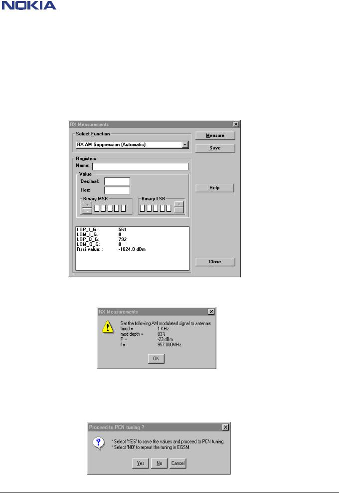
AM-suppression tuning in NHM-2/5/6
Due to a software failure in the latest NHM-2/5/6 DLL 311.15.00 it is necessary to run AM-suppression tuning in a special way, as described in the following pages. In case you do not use this procedure the AM-suppression tuning values will not be saved and WinTesla will not recognize the new values. So no warning message will be performed.
In the first step you have to activate AM-suppression tuning as usual (Tuning/AM Suppression…):
Click on the “Measure” button to get the next window, which shows the signal values you have to adjust, then click “OK”.
After correct AM-suppression tuning in EGSM900 (RSSI-level shown in the measurement window is < -86dBm) you get the message to proceed the tuning in PCN. At this point do not press “YES” as, differently from the message box, the tuning values will not be saved by choosing this button.
Click the button “Cancel” so that only the window shown on next page is performed on the screen.
© NMP 2002
Checked by: |
Approved by: |
Customer Care E&A |
SCCE Training Group |
|
CONFIDENTIAL |
9 (44) |
|
NHM—2/5/6 |
Repairhints |
Customer Care Europe, Middle East & Africa |
3410 |
Version 4.0 Approved |
SCCE Training Group |
Date 20.11.2002 |
|
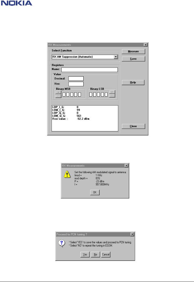
To save the tuning values you have to click the “Save” button in this window.
Afterwards start the tuning procedure again by pressing the “Measure” button, because tuning in PCN yet must be done.
Next appearing window is shown below. Press “OK” (it is not necessary to choose correct signal values).
After having done AM-suppression tuning in EGSM900 a second time, press the “Yes” button.
As effect the tuning values of EGSM900 will not be stored (but these tuning values have been stored before). You will be shown the message box as on next page so that you can continue tuning in PCN band.
© NMP 2002
Checked by: |
Approved by: |
Customer Care E&A |
SCCE Training Group |

|
CONFIDENTIAL |
10 (44) |
|
NHM—2/5/6 |
Repairhints |
Customer Care Europe, Middle East & Africa |
3410 |
Version 4.0 Approved |
SCCE Training Group |
Date 20.11.2002 |
|
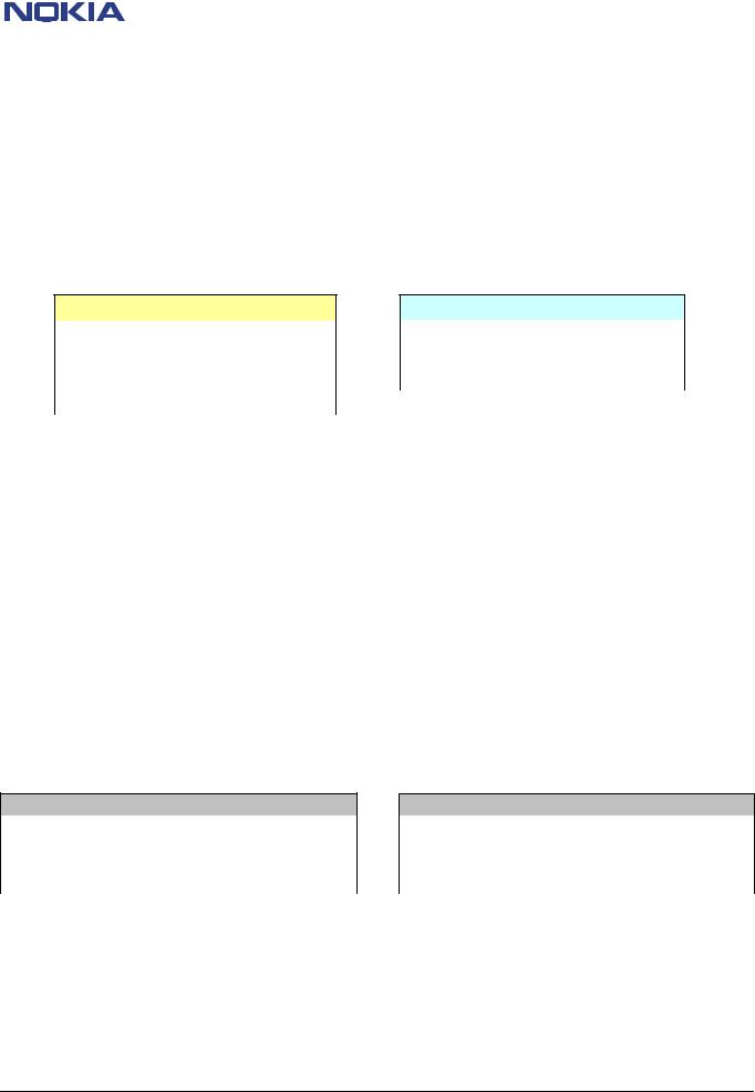
Set generator to the signal values mentioned in the control box. Then press the “OK” button.
To save the tuning values of AM-suppression in PCN band, do not use the “Yes” button. As in the case of EGSM900 choose the “Cancel” button and click the “Save” button in the remaining window. RSSI-level in PCN tuning must be < -90dBm!
Now AM-suppression has been performed in both EGSM and PCN and you can leave the tuning by choosing “Close”.
© NMP 2002
Checked by: |
Approved by: |
Customer Care E&A |
SCCE Training Group |
|
CONFIDENTIAL |
11 (44) |
|
NHM—2/5/6 |
Repairhints |
Customer Care Europe, Middle East & Africa |
3410 |
Version 4.0 Approved |
SCCE Training Group |
Date 20.11.2002 |
|
CHAPTER 1: HW-CHANGES
Difficulties when removing B-Cover (SB13 / NHM-5)
Cut away the guiding pin of the D-Cover (see Figure 1-1), if customer critisizes bad removal of B-Cover. After this procedure it is necessary to assemble the phone with a torque screwdriver prepared for 30Ncm!
Figure 1-1
Intermittent switch - off problem (SB17 / NHM-2, SB 28 & 55 / NHM-5, SB 7 / NHM-6)
The change of R301 from 2x 2.2 k? to 2x100 ? because of “Intermittet switches off” not needed anymore since HW 0813 on UP4IV, 0814 on UD4, 0815 on UG4 (NHM-5; SB 55), HW 0817 on UW4, 0818 on UW4II and 0819 on UX4 (NHM-6; SB 32) as in the new HW version this change is already done. The change of R301 should be a solution in earlier HW versions only.
All NHM-2 HW versions have the correct value implemented already in production (SB – 017). “Intermittet switches off” could be caused also by old ST flash, i.e. from before Week 02/2001. Therefore it is recommended to use newer ST Flash IC.
Note that SB 28 & 55 replaces the SB 12. Do not use this procedure anymore!
© NMP 2002
Checked by: |
Approved by: |
Customer Care E&A |
SCCE Training Group |
|
CONFIDENTIAL |
12 (44) |
|
NHM—2/5/6 |
Repairhints |
Customer Care Europe, Middle East & Africa |
3410 |
Version 4.0 Approved |
SCCE Training Group |
Date 20.11.2002 |
|
Correct component replacement in UB4_ 10 or later of NHM-5 (SB053) and NHM-6 (SB31)
If changing the power amplifier (N502) & antenna switches (Z502) is necessary, it is recommended to replace with the same type as the removed one.
The information in tables “PA vendor depent RF discrete component mount” and “Ant.sw./diplexer depent RF discrete components mounts” in NHM-5/6 Service Manual must be followed if there is a really essential reason to use different type of power amplifier or antenna switch as replacement
Only the following combinations of power amplifier and antenna are allowed for NHM-5/6:
NHM-5
Power Amplifier |
Antenna Switch |
Hitachi (4350259) |
Murata (4550131) |
Phillips (4350269) |
Matushita (4550201) |
RFMD (4350277) |
Matushita (4550201) |
NHM-6
Power Amplifier |
Antenna Switch |
Hitachi (4350259) |
Murata (4550131) |
Phillips (4350269) |
Murata (4550131) |
Note:
-After changing Power Amplifier, TX Power Tuning has to be carrying out.
-After changing Antenna Switch, Tx Power Tuning and RX Calibrations have to be carrying out.
After the Power Amplifier replacements, additional it should be checked in which constellation R311 and R312 were assembled (marked “X”).
If necessary, adjust the resistors in the corresponding order to the type of PA. Use for it the table below (PA vendor detection) as reference. (NHM-5; SB 25)
This is important because of the differences between the three power amplifier versions in use.
In UP4 Hitachi PA has been used while UD4 includes Philips PA and UG4 uses RFMD power amplifier. Last mentioned is available as spare part meanwhile.
For PCB version up to Version 09
PA vendor detection
PA vendor |
Part. No. |
R312 (PA_vendor2) |
R311 (PA_vendor1) |
RFMD |
435X231 |
Mounted |
|
Phillips |
435X194 |
|
Mounted |
Hitachi |
4350259 |
|
|
PCB version 10 and later
PA vendor detection
PA vendor |
Part. No. |
R312 (PA_vendor2) |
R311 (PA_vendor1) |
RFMD |
435X231 |
Mounted |
Mounted |
Phillips |
435X194 |
|
Mounted |
Hitachi |
4350259 |
Mounted |
|
© NMP 2002
Checked by: |
Approved by: |
Customer Care E&A |
SCCE Training Group |

|
CONFIDENTIAL |
13 (44) |
|
NHM—2/5/6 |
Repairhints |
Customer Care Europe, Middle East & Africa |
3410 |
Version 4.0 Approved |
SCCE Training Group |
Date 20.11.2002 |
|
HW Change description Overview of NHM-2/6
Part list |
PCB version |
Hitachi PA |
Philips PA |
RFMD PA |
Antenna switch Matsushita |
Antenna switch MURATA |
VCO 4.0GHz FDK |
VCO 4.0GHz Matsushita |
VCTCXO NDK |
VCTCXO Toyocom |
TX SAW filter Epcos (Note 3) |
TX SAW filter Panasonic (Note 3) |
Cobba TI A12 (Note 4) |
(UW4 & UW4II) GSM TX Out match New |
SCLK) Resistor' s MAD2WD1-Hagar |
UB4 11 PCB |
match (UX4) Hagar GSM1800 Output |
Hagar v5 |
Cobba ST optical shrink (Note 4) |
UB4 12 PCB |
Cobba TI A07 (Note 4) |
HW id - App. & Fixed |
UW4 |
UB4_10 |
X |
|
|
|
X |
|
X |
X |
|
X |
|
|
X |
|
|
|
|
|
|
|
08.06 |
UW4 |
UB4_10 |
X |
|
|
|
X |
|
X |
X |
|
X |
|
|
X |
X |
|
|
|
|
|
|
08.17 |
|
|
|
|
|
|
|
|
|
|
|
|
|
|
|
|
|
|
|
|
|
|
|
UW4 |
UB4_11 |
X |
|
|
|
X |
|
X |
X |
|
X |
|
|
X |
X |
X |
|
|
|
|
|
09.03 |
|
|
|
|
|
|
|
|
|
|
|
|
|
|
|
|
|
|
|
|
|
|
|
UW4 |
UB4_11 |
X |
|
|
|
X |
|
X |
X |
|
X |
|
|
X |
X |
X |
|
|
X |
|
|
09.15 |
|
|
|
|
|
|
|
|
|
|
|
|
|
|
|
|
|
|
|
|
|
|
|
UW4 |
UB4_11 |
X |
|
|
|
X |
|
X |
X |
|
X |
|
|
X |
X |
X |
|
X |
X |
|
|
09.23 |
|
|
|
|
|
|
|
|
|
|
|
|
|
|
|
|
|
|
|
|
|
|
|
UW4 |
UB4_12 |
X |
|
|
|
X |
|
X |
X |
|
X |
|
|
X |
X |
|
|
X |
X |
X |
|
10.03 |
|
|
|
|
|
|
|
|
|
|
|
|
|
|
|
|
|
|
|
|
|
|
|
UW4 |
UB4_12 |
X |
|
|
|
X |
|
X |
X |
|
X |
|
X |
X |
X |
|
|
X |
X |
X |
X |
10.24 |
|
|
|
|
|
|
|
|
|
|
|
|
|
|
|
|
|
|
|
|
|
|
|
UX4 |
UB4_10 |
|
X |
|
|
X |
X |
|
|
X |
|
X |
|
|
|
|
|
|
|
|
|
08.07 |
|
|
|
|
|
|
|
|
|
|
|
|
|
|
|
|
|
|
|
|
|
|
|
UX4 |
UB4_10 |
|
X |
|
|
X |
X |
|
|
X |
|
X |
X |
|
|
|
|
|
|
|
|
08.11 |
|
|
|
|
|
|
|
|
|
|
|
|
|
|
|
|
|
|
|
|
|
|
|
UX4 |
UB4_10 |
|
X |
|
|
X |
X |
|
|
X |
|
X |
X |
|
X |
|
|
|
|
|
|
08.19 |
|
|
|
|
|
|
|
|
|
|
|
|
|
|
|
|
|
|
|
|
|
|
|
UX4 |
UB4_10 |
|
X |
|
|
X |
X |
|
|
X |
|
X |
X |
|
X |
|
X |
|
|
|
|
08.23 |
|
|
|
|
|
|
|
|
|
|
|
|
|
|
|
|
|
|
|
|
|
|
|
UX4 |
UB4_11 |
|
X |
|
|
X |
X |
|
|
X |
|
X |
X |
|
X |
X |
|
|
|
|
|
09.05 |
|
|
|
|
|
|
|
|
|
|
|
|
|
|
|
|
|
|
|
|
|
|
|
UX4 |
UB4_11 |
|
X |
|
|
X |
X |
|
|
X |
|
X |
X |
|
X |
X |
X |
|
|
|
|
09.07 |
|
|
|
|
|
|
|
|
|
|
|
|
|
|
|
|
|
|
|
|
|
|
|
UX4 |
UB4_11 |
|
X |
|
|
X |
X |
|
|
X |
|
X |
X |
|
X |
X |
X |
X |
|
|
|
09.25 |
|
|
|
|
|
|
|
|
|
|
|
|
|
|
|
|
|
|
|
|
|
|
|
UX4 |
UB4_12 |
|
X |
|
|
X |
X |
|
|
X |
|
X |
X |
|
X |
|
X |
X |
|
X |
|
10.05 |
|
|
|
|
|
|
|
|
|
|
|
|
|
|
|
|
|
|
|
|
|
|
|
UX4 |
UB4_12 |
|
X |
|
|
X |
X |
|
|
X |
|
X |
X |
|
X |
|
X |
X |
X |
X |
X |
10.26 |
|
|
|
|
|
|
|
|
|
|
|
|
|
|
|
|
|
|
|
|
|
|
|
UW4II |
UB4_10 |
X |
|
|
|
X |
X |
|
|
X |
|
X |
|
X |
|
|
|
|
|
|
|
08.09 |
|
|
|
|
|
|
|
|
|
|
|
|
|
|
|
|
|
|
|
|
|
|
|
UW4II |
UB4_10 |
X |
|
|
|
X |
X |
|
|
X |
|
X |
|
X |
X |
|
|
|
|
|
|
08.18 |
|
|
|
|
|
|
|
|
|
|
|
|
|
|
|
|
|
|
|
|
|
|
|
UW4II |
UB4_10 |
X |
|
|
|
X |
|
X |
|
X |
|
X |
|
X |
X |
|
|
|
|
|
|
08.21 |
|
|
|
|
|
|
|
|
|
|
|
|
|
|
|
|
|
|
|
|
|
|
|
UW4II |
UB4_11 |
X |
|
|
|
X |
X |
|
|
X |
|
X |
|
X |
X |
X |
|
|
|
|
|
09.04 |
|
|
|
|
|
|
|
|
|
|
|
|
|
|
|
|
|
|
|
|
|
|
|
UW4II |
UB4_11 |
X |
|
|
|
X |
|
X |
|
X |
|
X |
|
X |
X |
X |
|
|
|
|
|
09.09 |
|
|
|
|
|
|
|
|
|
|
|
|
|
|
|
|
|
|
|
|
|
|
|
UW4II |
UB4_11 |
X |
|
|
|
X |
|
X |
|
X |
|
X |
X |
X |
X |
X |
|
|
|
|
|
09.10 |
|
|
|
|
|
|
|
|
|
|
|
|
|
|
|
|
|
|
|
|
|
|
|
UW4II |
UB4_11 |
X |
|
|
|
X |
X |
|
|
X |
|
X |
X |
X |
X |
X |
|
|
|
|
|
09.11 |
|
|
|
|
|
|
|
|
|
|
|
|
|
|
|
|
|
|
|
|
|
|
|
UW4II |
UB4_11 |
X |
|
|
|
X |
X |
|
|
X |
|
X |
X |
X |
X |
X |
|
X |
|
|
|
09.24 |
|
|
|
|
|
|
|
|
|
|
|
|
|
|
|
|
|
|
|
|
|
|
|
UW4II |
UB4_12 |
X |
|
|
|
X |
X |
|
|
X |
|
X |
X |
X |
X |
|
|
X |
|
X |
|
10.04 |
|
|
|
|
|
|
|
|
|
|
|
|
|
|
|
|
|
|
|
|
|
|
|
UW4II |
UB4_12 |
X |
|
|
|
X |
X |
|
|
X |
|
X |
X |
X |
X |
|
|
|
|
X |
|
10.10 |
|
|
|
|
|
|
|
|
|
|
|
|
|
|
|
|
|
|
|
|
|
|
|
UW4II |
UB4_12 |
X |
|
|
|
X |
X |
|
|
X |
|
X |
X |
X |
X |
|
|
X |
X |
X |
X |
10.25 |
|
|
|
|
|
|
|
|
|
|
|
|
|
|
|
|
|
|
|
|
|
|
|
UW5 |
UB4_12 |
X |
|
|
|
X |
|
X |
X |
|
X |
|
|
X |
X |
|
|
X |
X |
X |
|
10.07 |
|
|
|
|
|
|
|
|
|
|
|
|
|
|
|
|
|
|
|
|
|
|
|
UW5 |
UB4_12 |
X |
|
|
|
X |
|
X |
X |
|
X |
|
X |
X |
X |
|
|
X |
|
X |
|
10.11 |
|
|
|
|
|
|
|
|
|
|
|
|
|
|
|
|
|
|
|
|
|
|
|
UW5 |
UB4_12 |
X |
|
|
|
X |
|
X |
X |
|
X |
|
X |
X |
X |
|
|
X |
X |
X |
X |
10.28 |
|
|
|
|
|
|
|
|
|
|
|
|
|
|
|
|
|
|
|
|
|
|
|
UW5 |
UB4_12 |
X |
|
|
|
X |
|
X |
X |
|
X |
|
X |
X |
X |
|
|
X |
X |
X |
X |
10.35 |
|
|
|
|
|
|
|
|
|
|
|
|
|
|
|
|
|
|
|
|
|
|
|
© NMP 2002
Checked by: |
Approved by: |
Customer Care E&A |
SCCE Training Group |

|
CONFIDENTIAL |
14 (44) |
|
NHM—2/5/6 |
Repairhints |
Customer Care Europe, Middle East & Africa |
3410 |
Version 4.0 Approved |
SCCE Training Group |
Date 20.11.2002 |
|
CHAPTER 2: CHANGING OF D301
This chapter describes step by step how to change FLASH/EEPROM-combination D301 in NHM-2/5/6 phones:
If you want to change D301 the first you always have to do is a backup of the phone identity information. Therefore use WinTesla. Under “View” open the window “Phone Information”:
Figure 2-1
If you have no possibility to save this data (e.g. phone does not switch on because of defect D301), it is necessary to give the phone a new identity!
Having saved the phone identity information, you can now remove D301 and resolder the spare part – always use approved µBGA rework machine for changing any µBGA!
Because of the empty Flash the phone will not switch on, after changing D301. So the next action is to make a SW-update. Start WinTesla and choose Product / Open / NHM-5 and press ok. Now you will receive the following message:
Figure 2-2
If you select Yes, WinTesla will start and you can choose Dealer / Flash Phone, and the window shown on the next page appeares:
© NMP 2002
Checked by: |
Approved by: |
Customer Care E&A |
SCCE Training Group |
 Loading...