


3510
Customer Care Europe, Middel East & Africa NHM-8 / RH-9 Repairhints
SCCE Training Group Version 3.0 Approved
2003 Nokia Mobile Phones
CONFIDENTIAL
Date 27-11-2003
1 (19)
Repair Hints
Service-Level 3 & 4
3510 / 3510i
NHM-8 RH-9
© NMP 2003
Checked by: SCCE
Approved by: Training Group
Customer Care Europe, Middel East & Africa NHM-8 / RH-9 Repairhints
SCCE Training Group Version 3.0 Approved
2003 Nokia Mobile Phones
CONFIDENTIAL
Date 27-11-2003
2 (19)
GENERAL
-How to use this document
Put the colored schematics behind this manual.
Now you are able to follow these specifications with graphical layouts and it is easier for you to find the
components and measuring points.
-Component characteristics
Some components contain important data as tuning values or security data, therefore several steps
described are only feasible if you are able to reflash/ realign the phone and/or rewrite IMEI/SIMlock in
certain cases. Please pay attention to separate notes.
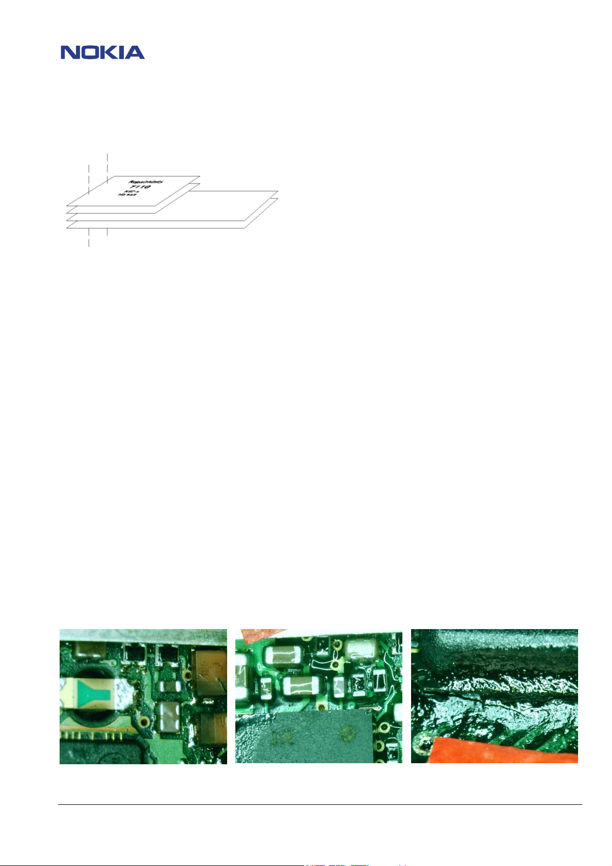
-Broken balls / underfill, µBGAs
All replaceable (not underfilled) µBGA components must be renewed after removing. Reflow with
uncontrolled hot air fan is strictly forbidden! µBGA must only be soldered with NMP approved µBGA rework
machines (e.g. Zevac / OK-Metcal / Martin) to get durable soldering joints.
After removing a µBGA check soldering points, if necessary rework oxidated solderings (broken balls)
carefully by tinplating these areas with few flux and a hot soldering iron. Before placing a new component
remove the tin and clean the PCB, e.g. with help of soder wick and flux cleaner such as “Kontakt LR”.
Use only recommended Fluxtype and an appropriate amount of it – avoid drowning the PCB in flux as this
will result in additional faults!
Also check underfilled parts for broken underfill material below. In this case carefully evaluate possible
repair actions as the phone probably was exposed to strong mechanical stress.
“rework” done with uncontrolled hot air PCB drowned in flux broken underfill of an µBGA part
© NMP 2003
Checked by: SCCE
Approved by: Training Group
Customer Care Europe, Middel East & Africa NHM-8 / RH-9 Repairhints
SCCE Training Group Version 3.0 Approved
2003 Nokia Mobile Phones
CONFIDENTIAL
Date 27-11-2003
3 (19)
-PCB handling & cleaning
To avoid damages of PCB and/or components through electrostatic discharging, handle the module in
ESD-suitable cases only. When handling PCBs outside an ESD-bag always wear ESD-bracelets, which must
be connected to earth bonding point. Damage by electrostatic discharge often leads to a module not failing
directly but in a short period of time!
For cleaning use only appropriate materials, do not use scratching or rubbing tools. Useful tools for cleaning
are fluxcleaners such as “Kontakt LR” or “Electrolube FLU” in connection with ionized compressed air.
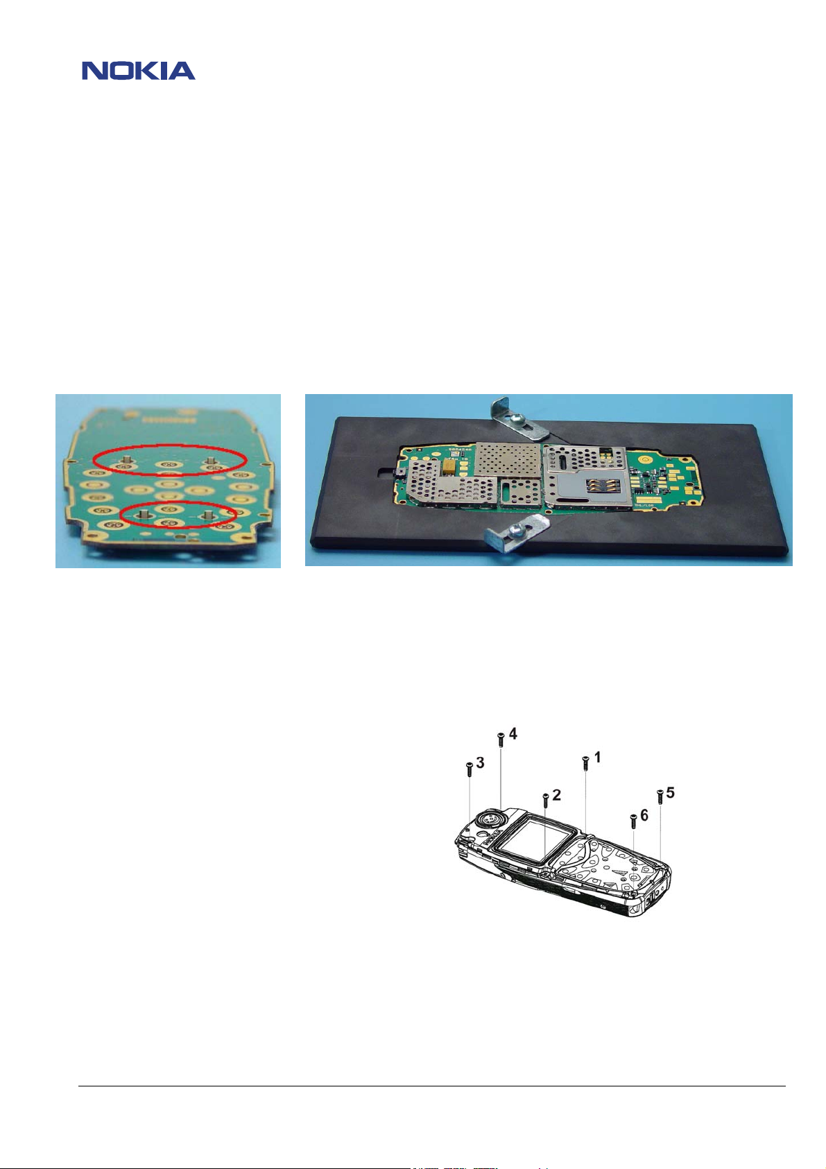
For shield disassembling or any other work on the PCB it is very important to place the PCB into the rework
jig MJS-67 (NMP-code 0770388) to prevent damaging the LEDs – the pads the LEDs are connected with to
the PCB are torn off by applying only little pressure onto the PCB!!!
-Shieldings, screw torques
To avoid RF-problems it is not allowed to reuse any shielding that once has been removed from PCB. Always
use new shieldings after successful repair!
To tighten screws only use a torque screwdriver with a torque adjusted to 28Ncm. Notice tightening order
that is shown in the picture below!
-Realign after repair
Characteristics of replacement parts may vary.
To prevent additional faults after repair (e.g. low standby time, losing network etc.) it is necessary to retune
phone values after repair, but never try to cover up a fault by justing the phone settings!
© NMP 2003
Checked by: SCCE
Approved by: Training Group
CONFIDENTIAL
4 (19)
Customer Care Europe, Middel East & Africa NHM-8 / RH-9 Repairhints
SCCE Training Group Version 3.0 Approved
2003 Nokia Mobile Phones
Date 27-11-2003
INTRODUCTION
IMPORTANT:
This document is intended for use by authorized NOKIA service centers only.
The purpose of this document is to provide some further service information for NOKIA 3510/3510i phones.
It contains a lot of collected tips and hints to find faults and repair solutions easily.
It also will give support to inexperienced technicians.
Saving process time and improving the repair quality is the aim of this document.
It is built up based on fault symptoms (listed in "Contents") followed by detailed description for further analysis.
The document is to be used additionally to the service manual and other service information such as Service Bulletins. For that
reason it does not contain any circuit or schematic diagrams.
All measurements are made using following equipment:
Nokia repair SW: Phoenix version 04.13.005
MCU SW: 4.24 for 3510; 3.51 for 3510i
Nokia module jig: MJS - 37
Digital multimeter: Fluke 73
Oscilloscope: Fluke PM 3380A/B
Spectrum Analyzer: Advantest R3131 with an analog probe
RF-Generator / GSM Tester: Rohde & Schwarz CMU 200
While every endeavour has been made to ensure the accuracy of this document, some errors may exist. If the reader finds any
errors, NOKIA should be notified in writing, using the following procedure:
Please state:
title of the document + issue number/date of publication.
page(s) and/or figure(s) in error.
Please send to: Nokia GmbH
Service & Competence Center Europe
Meesmannstr.103
D-44807 Bochum / Germany
Copyright © Nokia Mobile Phones.
This material, including documentation and any related computer programs is protected by copyright, controlled by Nokia Mobile
Phones. All rights are reserved. Copying, including reproducing, modifying, storing, adapting or translating any or all of this
material requires the prior written consent of Nokia Mobile Phones. This material also contains confidential information, which
may not be disclosed to others without the prior written consent of Nokia Mobile Phones.
© NMP 2003
Checked by: SCCE
Approved by: Training Group
CONFIDENTIAL
5 (19)
Customer Care Europe, Middel East & Africa NHM-8 / RH-9 Repairhints
SCCE Training Group Version 3.0 Approved
2003 Nokia Mobile Phones
Date 27-11-2003
Contents
PREFACE
CHAPTER 1
CHAPTER 2
CHAPTER 3
CHAPTER 4
CHAPTER 5
CHAPTER 6
CHAPTER 7
CHAPTER 8
CHAPTER 9
General 2
Introduction 4
List of figures 6
CTI calibration 7
Phone does not switch on 8
Phone switches off itself 12
Charging faults 13
SIM card faults 14
User interface faults 15
No service 17
Change history 19
© NMP 2003
Checked by: SCCE
Approved by: Training Group
CONFIDENTIAL
6 (19)
Customer Care Europe, Middel East & Africa NHM-8 / RH-9 Repairhints
SCCE Training Group Version 3.0 Approved
2003 Nokia Mobile Phones
Date 27-11-2003
CHAPTER 1: List of figures
Figure Chapter Page
1: 32.768kHz sinewave at C209 3 9
2: 32.768kHz sinewave at C210 3 9
3: 26MHz sinewave at B600 3 9
4: 26MHz reference clock at J425 (measured with spectrum analyzer) 3 10
5: 32.768kHz SLEEPCLK squarewave at J404 3 11
6: 26MHz reference clock at J425 (measured with oscilloscope) 3 11
7: VSIM measured without SIM card at pogo pins of service jig 5 13
8: 26MHz reference clock at J425 (measured with oscilloscope) 8 16
9: TXC at R637 (TX powerlevel 10) 8 16
10: TXP at C646 8 16
11: TXIQ at R610 / R611 8 16
12: RFBusData at J610 8 16
13: RFBusClock at J608 8 16
14: RFBusEnable at J609 8 16
15: VPCTRL_G at R713 8 17
16: VTX_B_G at R717 8 17
17: VTXLO_G at R716 8 17
© NMP 2003
Checked by: SCCE
Approved by: Training Group
 Loading...