


PAMS Technical Documentation
Chapter 4
UI Module UE4S
Original 03/98

|
PAMS |
|
|
UI Module UE4S |
Technical Documentation |
CONTENTS
UIF Module . . . . . . . . . . . . . . . . . . . . . . . . . . . . . . . . . . . . . . . . . . . . |
4±3 |
Introduction . . . . . . . . . . . . . . . . . . . . . . . . . . . . . . . . . . . . . . . . . . |
4±3 |
Baseband Block Diagram . . . . . . . . . . . . . . . . . . . . . . . . . . . |
4±4 |
The Engine Interface . . . . . . . . . . . . . . . . . . . . . . . . . . . . . . . |
4±5 |
The LCD Module Interface . . . . . . . . . . . . . . . . . . . . . . . . . . |
4±7 |
Functional Description . . . . . . . . . . . . . . . . . . . . . . . . . . . . . . . . |
4±8 |
Power Distribution Diagram . . . . . . . . . . . . . . . . . . . . . . . . . . |
4±8 |
Display Circuit . . . . . . . . . . . . . . . . . . . . . . . . . . . . . . . . . . . . . |
4±8 |
Keyboard . . . . . . . . . . . . . . . . . . . . . . . . . . . . . . . . . . . . . . . . . |
4±9 |
Keyboard Matrix . . . . . . . . . . . . . . . . . . . . . . . . . . . . . . . . . . . |
4±10 |
Power Key . . . . . . . . . . . . . . . . . . . . . . . . . . . . . . . . . . . . . . . . |
4±10 |
Backlighting . . . . . . . . . . . . . . . . . . . . . . . . . . . . . . . . . . . . . . . |
4±11 |
Display . . . . . . . . . . . . . . . . . . . . . . . . . . . . . . . . . . . . . . . . . . . |
4±12 |
Keyboard . . . . . . . . . . . . . . . . . . . . . . . . . . . . . . . . . . . . . . . . . |
4±12 |
Buzzer . . . . . . . . . . . . . . . . . . . . . . . . . . . . . . . . . . . . . . . . . . . . |
4±12 |
Speaker . . . . . . . . . . . . . . . . . . . . . . . . . . . . . . . . . . . . . . . . . . |
4±13 |
Parts list of UE4S (EDMS Issue 4.1) Code: 0201144 . . . . . . . . |
4±14 |
Schematic Diagrams UIF/A3 |
|
Circuit Diagram of UIF Module (Version 3 Edit 49) for layout 03 |
4/A3±1 |
Circuit Diagram of Speaker and LCD Modules for layout 03 . . |
4/A3±2 |
Circuit Diagram of Keyboard (Version 3 Edit 45) for layout 03 . |
4/A3±3 |
Layout Diagram of UE4S (Version 03) . . . . . . . . . . . . . . . . . . . . . |
4/A3±4 |
Page 4±2 |
Original 03/98 |
PAMS
Technical Documentation |
UI Module UE4S |
UIF Module
Introduction
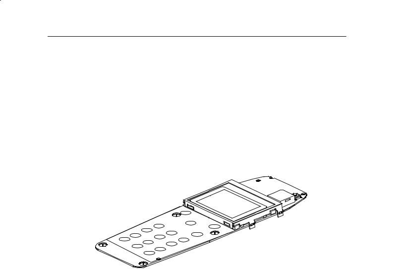
The UI module UE4S is a four layer PCB, which is connected to the system/RF PCB with a 28±pin spring connector.
Original 03/98 |
Page 4±3 |

PAMS
UI Module UE4S |
Technical Documentation |
Baseband Block Diagram
Page 4±4 |
Original 03/98 |
PAMS
Technical Documentation |
UI Module UE4S |
The Engine Interface
Pin |
Line Sym- |
Parameter |
Min |
Typ |
Max |
Unit |
Notes |
|
bol |
|
|
|
|
|
|
1 |
ROW0 |
Keyboard matrix row 0 |
0 |
|
0.3xVBB |
V |
Low |
|
|
|
0.7xVBB |
|
VBB |
|
High |
|
|
|
|
|
|
|
|
2 |
ROW1 |
Keyboard matrix row 1 |
0 |
|
0.3xVBB |
V |
Low |
|
|
|
0.7xVBB |
|
VBB |
|
High |
|
|
|
|
|
|
|
|
3 |
ROW2 |
Keyboard matrix row 2 |
0 |
|
0.3xVBB |
V |
Low |
|
|
|
0.7xVBB |
|
VBB |
|
High |
|
|
|
|
|
|
|
|
4 |
ROW3 |
Keyboard matrix row 3 |
0 |
|
0.3xVBB |
V |
Low |
|
|
|
0.7xVBB |
|
VBB |
|
High |
|
|
|
|
|
|
|
|
5 |
ROW4 |
Keyboard matrix row 4 |
0 |
|
0.3xVBB |
V |
Low |
|
|
|
0.7xVBB |
|
VBB |
|
High |
|
|
|
|
|
|
|
|
6 |
COL0 |
Keyboard matrix column 0, |
0 |
|
0.3xVBB |
V |
Flip Open |
|
|
used for flip identification |
|
|
|
|
|
|
|
|
0.7xVBB |
|
VBB |
|
Flip Closed |
|
|
|
|
|
|
|
|
7 |
COL1 |
Keyboard matrix column 1 |
0 |
|
0.3xVBB |
V |
Low |
|
|
|
0.7xVBB |
|
VBB |
|
High |
|
|
|
|
|
|
|
|
8 |
COL2 |
Keyboard matrix column 2 |
0 |
|
0.3xVBB |
V |
Low |
|
|
|
0.7xVBB |
|
VBB |
|
High |
|
|
|
|
|
|
|
|
9 |
COL3 |
Keyboard matrix column 3 |
0 |
|
0.3xVBB |
V |
Low |
|
|
|
0.7xVBB |
|
VBB |
|
High |
|
|
|
|
|
|
|
|
10 |
COL4 |
Keyboard matrix column 4 |
0 |
|
0.3xVBB |
V |
Low |
|
|
|
0.7xVBB |
|
VBB |
|
High |
|
|
|
|
|
|
|
|
11 |
Signal1 |
Flip interrupt, not used |
0 |
|
0.3xVBB |
V |
|
|
|
|
0.7xVBB |
|
VBB |
|
|
|
|
|
|
|
|
|
|
12 |
VF_IN |
Flash in |
4.8 |
5.0 |
5.2 |
V |
Connected #13 |
|
|
|
|
|
|
|
|
13 |
VF_OUT |
Flash out |
4.8 |
5.0 |
5.2 |
V |
Connected #12 |
|
|
|
|
|
|
|
|
14 |
VBATT |
Battery voltage |
3.0 |
|
5.1 |
V |
|
|
|
|
|
|
|
|
|
|
|
|
60 |
75 |
100 |
mA |
For lights |
|
|
|
|
|
|
|
|
|
|
|
|
110 |
300 |
mA |
For buzzer |
|
|
|
|
|
|
|
|
15 |
UAGND* |
Analog ground |
|
0 |
|
V |
|
|
|
|
|
|
|
|
|
16 |
PWRON |
Power on key |
0 |
|
0.3xVBB |
V |
Low / Power on |
|
|
|
0.7xVBB |
|
VBB |
|
High |
|
|
|
|
|
|
|
|
17 |
LCDCDX |
LCD driver code/data selection |
0 |
|
0.3xVBB |
V |
Low |
|
|
|
0.7xVBB |
|
VBB |
|
High |
|
|
|
|
|
|
|
|
18 |
SCLK |
LCD driver serial clock |
0 |
|
0.3xVBB |
V |
Low |
|
|
|
0.7xVBB |
|
VBB |
|
High |
|
|
|
|
|
|
|
|
Original 03/98 |
Page 4±5 |
 Loading...