


INC
VBA24001-R.3783.A
VBA24001
REPAIR MANUAL
Copyright 2009 by Nikon Corporation. All Rights Reserved.
!!
Printed in Japan APRIL.2009
|
INC |
CONTENTS |
VBA24001-R.3783 .A |
|
|
Points to notice for Disassembly and Assembly ...................................................................................................................... |
D1 |
Disassembly ................................................................................................................................................................................ |
D2 |
1. External section ............................................................................................................................................................... |
D2 |
Bottom cover.................................................................................................................................................................. |
D2 |
Removal of back cover.................................................................................................................................................. |
D4 |
2. Back cover ........................................................................................................................................................................ |
D6 |
Sponge/Button/FPC/Speaker....................................................................................................................................... |
D8 |
SD cover unit............................................................................................................................................................... |
D10 |
SD cover........................................................................................................................................................................ |
D11 |
TFT monitor unit....................................................................................................................................................... |
D12 |
3. Front cover ..................................................................................................................................................................... |
D18 |
Pop-up of Flash unit (SB) ........................................................................................................................................... |
D18 |
Front cover................................................................................................................................................................... |
D18 |
4. Top cover ........................................................................................................................................................................ |
D19 |
TOGO PCB unit .......................................................................................................................................................... |
D19 |
Removal of top cover................................................................................................................................................... |
D20 |
SB upper cover............................................................................................................................................................ |
D21 |
SB lower control unit.................................................................................................................................................. |
D22 |
SB release base unit.................................................................................................................................................... |
D24 |
AF-assist lamp unit...................................................................................................................................................... |
D24 |
Power SW FPC unit .................................................................................................................................................... |
D25 |
Release button unit / each button, etc....................................................................................................................... |
D25 |
C/D unit ....................................................................................................................................................................... |
D26 |
Top cover FPC unit..................................................................................................................................................... |
D26 |
Mode dial unit / AF/AE-L button / Delete button / AF-assist lamp window ......................................................... |
D27 |
Hot shoe........................................................................................................................................................................ |
D27 |
5. Image sensor................................................................................................................................................................... |
D28 |
SZ-DC/DC PCB unit .................................................................................................................................................. |
D28 |
Image sensor unit......................................................................................................................................................... |
D28 |
6. Separation of Front body from Rear Body ................................................................................................................. |
D29 |
Bottom base unit.......................................................................................................................................................... |
D29 |
7. Rear body ....................................................................................................................................................................... |
D32 |
Microphone ................................................................................................................................................................. |
D32 |
Main condenser........................................................................................................................................................... |
D32 |
SB PCB unit ................................................................................................................................................................. |
D33 |
DC/DC PCB unit ........................................................................................................................................................ |
D34 |
Battery box.................................................................................................................................................................. |
D35 |
Eyelet unit, etc ............................................................................................................................................................ |
D36 |
8. Front body...................................................................................................................................................................... |
D37 |
Shutter ........................................................................................................................................................................ |
D37 |
- D5000 -
|
INC |
Meterring FPC unit |
VBA24001-R.3783 .A |
D38 |
|
Eyepiece barrel unit ................................................................................................................................................... |
D38 |
Penta unit .................................................................................................................................................................... |
D39 |
SI unit .......................................................................................................................................................................... |
D40 |
Relay PCB unit ........................................................................................................................................................... |
D42 |
Removal of bayonet..................................................................................................................................................... |
D43 |
Lens contact unit ......................................................................................................................................................... |
D43 |
SQ base unit ................................................................................................................................................................. |
D45 |
AF sensor unit ............................................................................................................................................................. |
D46 |
Inside finder LCD unit............................................................................................................................................... |
D46 |
plate .............................................................................................................................................................................. |
D47 |
Release button unit..................................................................................................................................................... |
D47 |
F-min SW section......................................................................................................................................................... |
D48 |
Mirror unit/Aperture lever section............................................................................................................................ |
D48 |
Assembly/Adjustment ............................................................................................................................................................... |
A1 |
1. Front body ....................................................................................................................................................................... |
A1 |
Mirror unit.................................................................................................................................................................... |
A1 |
Aperture lever section ................................................................................................................................................... |
A2 |
Spring hooking position................................................................................................................................................ |
A2 |
F-min SW section........................................................................................................................................................... |
A3 |
Release button unit....................................................................................................................................................... |
A3 |
plate ............................................................................................................................................................................... |
A4 |
Inside finder LCD unit................................................................................................................................................. |
A4 |
AF sensor unit ............................................................................................................................................................... |
A5 |
SQ PCB unit.................................................................................................................................................................. |
A5 |
Lens contact unit .......................................................................................................................................................... |
A7 |
Mounting of bayonet .................................................................................................................................................... |
A8 |
.......................................................................................................................... |
A9 |
Height adjustment of Aperture lever |
|
Relay-PCB unit ......................................................................................................................................................... |
A10 |
SI unit .......................................................................................................................................................................... |
A11 |
Attachment position for Finder field frame ............................................................................................................ |
A12 |
Penta unit .................................................................................................................................................................... |
A14 |
Eyepiece barrel unit ................................................................................................................................................... |
A15 |
AE FPC unit................................................................................................................................................................ |
A15 |
adjustment of Main mirror and Sub-mirror ........................................................................................................... |
A16 |
Shutter ......................................................................................................................................................................... |
A25 |
2. Rear body ....................................................................................................................................................................... |
A26 |
Eyelet unit, etc ............................................................................................................................................................ |
A26 |
Battery box.................................................................................................................................................................. |
A27 |
DC/DC PCB unit ........................................................................................................................................................ |
A29 |
SB PCB unit ................................................................................................................................................................. |
A30 |
Main condenser........................................................................................................................................................... |
A31 |
- D5000 -
|
INC |
Microphone |
VBA24001-R.3783 .A |
A31 |
|
3. Assembly of front body into rear body ........................................................................................................................ |
A32 |
Bottom base unit.......................................................................................................................................................... |
A33 |
Inspection and Adjustment of Body back ................................................................................................................ |
A34 |
4. Image sensor................................................................................................................................................................... |
A38 |
Sponge .......................................................................................................................................................................... |
A38 |
Image sensor unit........................................................................................................................................................ |
A38 |
SZ-DC/DC PCB unit .................................................................................................................................................. |
A39 |
5. Top cover ........................................................................................................................................................................ |
A40 |
Hot shoe........................................................................................................................................................................ |
A40 |
AF-assist lamp unit & AF/AE lock button ................................................................................................................ |
A40 |
Mode dial unit & Delete-button-rubber SW............................................................................................................. |
A41 |
Top cover FPC unit..................................................................................................................................................... |
A41 |
C/D unit ....................................................................................................................................................................... |
A42 |
Release button unit / each button, etc....................................................................................................................... |
A43 |
Power SW FPC unit .................................................................................................................................................... |
A43 |
AF-assist lamp unit...................................................................................................................................................... |
A44 |
SB release base unit.................................................................................................................................................... |
A44 |
SB lower control unit.................................................................................................................................................. |
A45 |
SB upper cover............................................................................................................................................................ |
A48 |
Top cover ..................................................................................................................................................................... |
A49 |
TOGO PCB unit .......................................................................................................................................................... |
A50 |
Inspection and adjustment of AE CCD positioning ................................................................................................ |
A51 |
Discharge of main condenser..................................................................................................................................... |
A52 |
6. Front cover ..................................................................................................................................................................... |
A53 |
Gap adjustment of SB (flash unit) section................................................................................................................... |
A53 |
7. Back cover ..................................................................................................................................................................... |
A54 |
TFT monitor unit....................................................................................................................................................... |
A54 |
Back cover................................................................................................................................................................... |
A61 |
Sponge/button/FPC/Speaker ...................................................................................................................................... |
A62 |
SD cover....................................................................................................................................................................... |
A65 |
SD cover unit............................................................................................................................................................... |
A66 |
8. External appearance ..................................................................................................................................................... |
A68 |
Accuracy inspection and adjustment (Camera body excl. imaging) .................................................................... |
A69 |
D5000 Inspection and Adjustment Software (J65135)............................................................................................. |
A70 |
Procedure for installation ........................................................................................................................................... |
A71 |
Procedure for installing USB driver .......................................................................................................................... |
A74 |
Necessary adjustments when parts are replaced...................................................................................................... |
A76 |
Firmware update ......................................................................................................................................................... |
A77 |
AE inspection and adjustment ................................................................................................................................... |
A84 |
AF inspection and adjustment.................................................................................................................................... |
A86 |
Bottom cover................................................................................................................................................................ |
A90 |
Shooting-image Adjustment ....................................................................................................................................... |
A91 |
- D5000 -
|
INC |
Shooting image adjustment software and Software updates |
VBA24001 - R.3783 .A |
................................................................................... A92 |
|
Image adjustment........................................................................................................................................................ |
A93 |
∞ Infinity focus inspection & adjustment ............................................................................................................... |
A97 |
Measurement of Consumption current value ........................................................................................................... |
A98 |
Cleaning between Penta unit and SI-LCD................................................................................................................ |
A99 |
Operation check of cleaning image sensor.............................................................................................................. |
A100 |
Hinge SW inspection ................................................................................................................................................. |
A103 |
Main/sub mirror angle inspection tool - use chart ................................................................................................. |
A104 |
Wiring ......................................................................................................................................................................................... |
E1 |
Mounting Drawing .................................................................................................................................................................... |
E2 |
Inspection standards.................................................................................................................................................................. |
R1 |
Tools ............................................................................................................................................................................................ |
T1 |
Screw sheet .................................................................................................................................................................................. |
S1 |
- D5000 -

INC
VBA24001-R.3783.A
Points to notice for Disassembly and Assembly
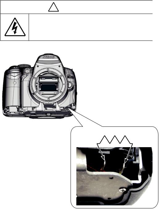
! WARNING
 There are high voltege parts inside. Be careful of this electric shock, when you remove the cover.
 You must discharge the main condenser according to the instruction of this repair manual after you remove the cover.
Caution:
In disassembly/(re)assembly, be sure to use conductive mat (J5033) and wrist strap (J5033-5), in order to protect electric parts from static electricity.
Before disassembling, be sure to remove batteries or AC power cord.
In disassembling, be sure to memorize the processing state of wires and FPC, screws to be fixed and their types, etc.
The low-pass filter of the image PCB/base plate is easily damaged. Handle it very carefully.
Points to notice for Lead-free solder products
Lead-free solder is used for this product.
For soldering work, the special solder and soldering iron are required.Do NOT mix up lead-free solder with traditional solder.
Caution:
When "Separation of Front body from Rear body", "Disassembly of Image sensor unit" and "Disassembly of Bayonet" are performed, be sure to carry out "RESET AF-DEFOCUS COMPENSATION" of the D5000 adjustment software after assembly.
- D1 D5000 -

INC
VBA24001-R.3783.A
Disassembly
1. External section
Bottom cover
Open and tilt the battery cover unit (#B151) at approx. 35° angle, then pull it out at the angle.
Open the power cable cover.
Take out the four screws (#735) and five screws (#671).
Remove the bottom cover (#25).
Approx. 35° 
#671
#25
#735
Power cable cover 
#735
- D2 D5000 -
INC
VBA24001-R.3783.A
! WARNING
 There are high voltege parts inside. Be careful of this electric shock, when you remove the cover.
 You must discharge the main condenser according to the instruction of this repair manual after you remove the cover.
2K Ω /5W
- D3 D5000 -

INC
VBA24001-R.3783.A
Removal of back cover
Take out the two screws (#618), the two screws (#690), the two screws (#697) and two screws (#740).
#618
#697 |
#690 |
#740
- D4 D5000 -
INC
VBA24001-R.3783.A
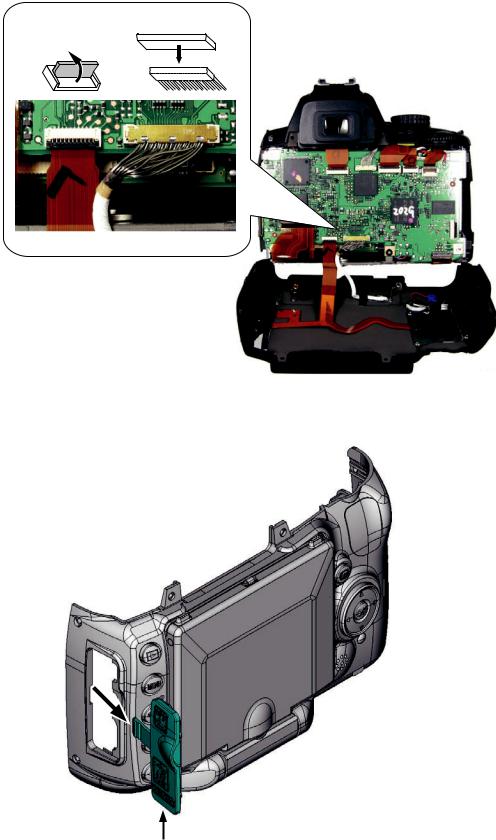
Remove the cover by lifting it at the grip side first, and then the whole.
Disconnect the FPC and harness (of the rear cover) from the connectors of the TOGO PCB UNIT(#B2001).
Remove the IF cover (#71).
#71
- D5 D5000 -
2.Back cover
Peel off the tape (#705).
#705 |
Take out the two screws (#741).
Remove the hinge rear cover A (#445) and hinge rear cover B (#446).
#741
INC
VBA24001-R.3783.A
#446 |
|
|
|
|
|
|
#445 |
|
|
|
|
|
|
||
|
|||||||
|
|
|
|
- D6 D5000 -
INC
VBA24001-R.3783.A
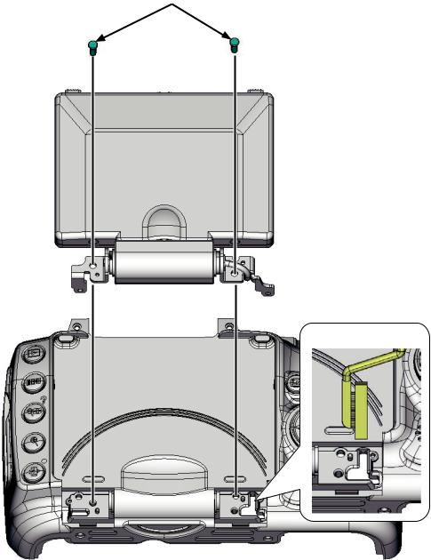
Take out the two screws (#682).
Remove the TFT monitor unit from the back cover.
When removing this, be careful not to catch the harness.)
#682
Be careful NOT to catch.
- D7 D5000 -

Sponge/Button/FPC/Speaker
Peel off the tape (#707).
Unsolder the speaker (#1047).
#707
#478
#471 
 #472
#472
#475 
 #474
#474

 #1047
#1047
#412
#418
#B1019
#413
#707
#415
INC
VBA24001-R.3783.A
#424
#425 


 #426
#426 


 #427
#427 

 #421
#421
#422
#683
#419
#683
#729
- D8 D5000 -

INC
VBA24001-R.3783.A
Peel off the tape (#477).
Peel off the tape (#706).
Remove the superglue from the SD access lamp window (#408), and remove [#408].
#706
#477
#408
Adhesive: Superglue
Remove the two rubbers (#473).
Remove the rubber (#469).
Peel off the double-stick tapes (#470 and #476).
#473
#469
#470
#476
- D9 D5000 -

INC
VBA24001-R.3783.A
SD cover unit
Take out the two screws (#684).
Remove the SD cover unit (#B443).
#684
#B443
Peel off the label (#448).
#448
- D10 D5000 -

INC
VBA24001-R.3783.A
SD cover
Take out the two screws, and remove the SD-cover click spring.
Pull out the shaft, and remove the SD-cover torsion spring. (Be careful NOT to lose the spring.)
Remove the plate from the SD cover (#443).
SD-cover torsion spring
Screw
SD-cover click spring
Shaft
Plate
#443
- D11 D5000 -

INC
VBA24001-R.3783.A
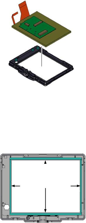
TFT monitor unit
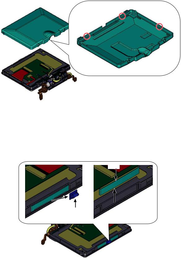
Remove the TFT window (#402), and peel off the TFT window double-sticking tape (#403).
Remove the sensor magnet (#490) from the TFT monitor unit (#B2049).
Remove the magnet spacer (#494) from the sensor magnet (#490).
#402
#403 |
#490 |
|
|
|
|
|
|
|
#494 |
#B2049
- D12 D5000 -

INC
VBA24001-R.3783.A
Take out the screw (#671).
Release the two inside hooks of the hinge bottom cover (#438), and remove the hinge top cover (#437).(Caution : must be exercised that each part do not get scratched or dented. If it does, use a new one.)
#671
#438
Unhook here |
Unhook here |
#437
Position [#B454] as below, and take out the two screws (#673) and two screws (#674).
#673
 #B454
#B454
#674
- D13 D5000 -
INC
VBA24001-R.3783.A
Release the three hooks, and remove the TFT top cover (#434).
[When removing this, be careful NOT to lose the lock-plate spring (#432) and lock knob (#431).] (Caution : must be exercised that each part does not get scratched or dented. If it does, use a new one.)
Back
#434
Remove the lock knob (#431).
Remove the lock-plate spring (#432).
#432
#431
- D14 D5000 -

#B454
- D15 D5000 -
INC
VBA24001-R.3783.A
Remove the harness (#1058) from the hinge unit (#B454)
#1058
#B454
Disconnect the FPC.
While passing the FPC through, remove the retaining plate (#406).
#406
- D16 D5000 -
INC
VBA24001-R.3783.A
Remove the TFT monitor unit (#B1049).
#B1049
Remove the two sponges (#404) and two sponges (#405).
#405 |
|
|
|
#405 |
|
#404 |
|||
- D17 D5000 -
INC
VBA24001-R.3783.A
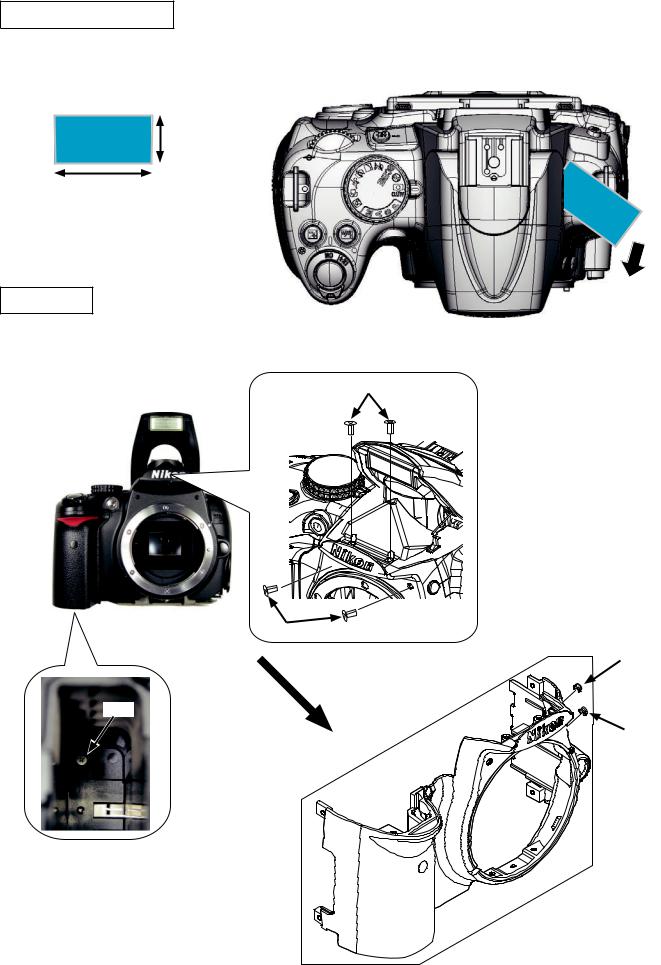
3. Front cover
Pop-up of Flash unit (SB)
Cut the lumirror sheet, etc, into the below size, and inset it in the clearance of the top cover pop-up section. Then, slide it in the direction of the arrow and raise (pop-up) the flash unit.
Approx. 2cm
Approx. 4cm
Front cover
Take out the four screws (#610) and the one screw (#626).
Remove the front cover unit (#B24).
#610
#610
|
|
#466 |
#626 |
#B24 |
|
|
#465 |
|
|
|
- D18 D5000 -

INC
VBA24001-R.3783.A
4. Top cover
TOGO PCB unit
Disconnect the seven FPCs, and remove the harness from the connector.
Unsolder the wires in the upper right [Red], upper left [Black/Red] and lower right [Blue/Red] corner of the PCB.
Take out the five screws (#663).
[Red]
#663 |
3 |
|
#663 |
[Blue/Red] |
#663 |
#663
Lift the one side of the PCB as below, and disconnect the connector of the back.
Remove the TOGO PCB unit (#B2001).
#B2001
Turn up
- D19 D5000 -
INC
VBA24001-R.3783.A
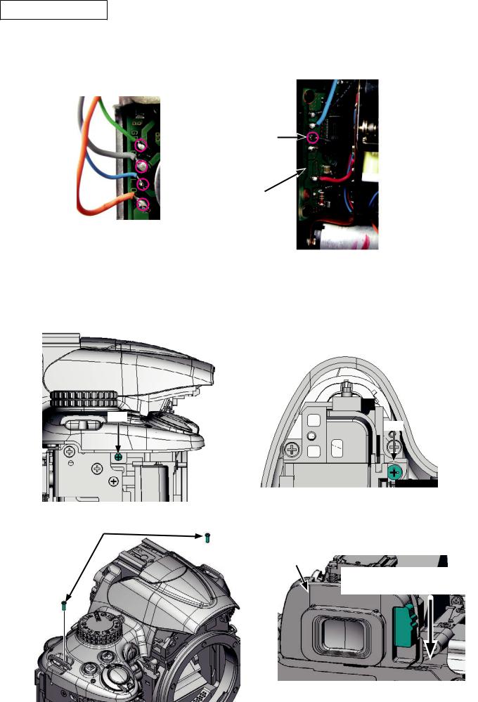
Removal of top cover
Remove the solders of the wires [Green/Gray/Blue/Orange] from the SB PCB unit (#B2006).
Remove the solder of the wire [Black] from the DC/DC PCB (#B2002).
[Green/Gray/Blue/Orange]
[Black]
#B2002
Take out the screw (#638).
Take out the screw (#607).
Take out the two screws (#737).
Remove the top cover and the eyepiece mold unit (#B271).
#607
#638
#737 × 2
#B271
Lowering this lever will facilitate the removal of [#B271].
- D20 D5000 -

INC
VBA24001-R.3783.A
SB upper cover
Push the SB lock lever in the direction of the arrow, and raise (pop-up) the built-in SB (flash unit).
SB lock lever
Take out the two screws (#632).
#632
House the SB lower control unit (#B302), and remove the SB upper cover (#301).
#301
- D21 D5000 -

INC
VBA24001-R.3783.A
SB lower control unit
Take out the screw (#650), and release the wires from the bosses.
Unsolder the wires [Red/Blue/Green/Black] of the top cover FPC unit (#B1012).
[Red/Blue/Green/Black]
#B1012
#650
Boss
Boss
Pull out the eight wires.
- D22 D5000 -

INC
VBA24001-R.3783.A
While pushing the rotate shaft (#306), take out the screw (#733) and remove the spring (#305).
Remove [#306].
Remove the SB rotating collar (#308), while releasing its two hooks.
Remove the SB lower control unit (#B302).
|
#733 |
|
#305 |
|
#B302 |
Unhook here. |
Remove this while |
pushing. |
#306
#308
Remove the two rubbers (#311).
11
- D23 D5000 -

INC
VBA24001-R.3783.A
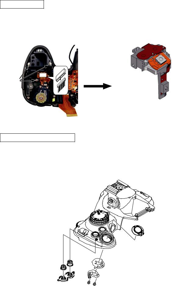
SB release base unit
Remove the solders of the wires [Red/Black] from the top cover FPC unit (#B1012).
Release the wires [Red/Black] from the guides.
Take out the two screws (#609), and remove the SB release base unit (#B2455).
Guide
#B2455
[Red/Black]
#609  #B1012
AF-assist lamp unit
Unsolder the wire [uncoated/Black].
Peel off the flocked sheet (#327).
Take out the screw (#608), and remove the AF-assist lamp unit (#B325).
#327
#608
[uncoated/Black]
#B325
- D24 D5000 -
INC
VBA24001-R.3783.A
Power SW FPC unit
Remove the FPC.
Take out the three screws (#635).
Remove the power SW FPC unit (#B1011).
#635
#B1011
Release button unit / each button, etc
Remove the rubber SW (#382), the + - /aperture button (#381) and the info button (#384).
Take out the two screws (#605).
Remove the on-off SW brush (#348), on-off click spring (#347), and on-off dial (#B345).
|
|
|
AU |
|
|
T |
|
|
|
O |
|
|
|
|
#B345 |
#381 |
#384 |
|
#347 |
|
|
||
|
|
|
|
|
|
#348 |
|
#382 |
|
#605 × 2 |
|
|
|
||
- D25 D5000 -
 Loading...