


 Loading...

 ® T 778
AV Surround Amplifier
ENGLISH
Owner’s Manual
ENGLISH
IMPORTANT SAFETY INSTRUCTIONS
1.Read instructions - All the safety and operating instructions should be read before the product is operated.
2.Retain instructions - The safety and operating instructions should be retained for future reference.
3.Heed Warnings - All warnings on the product and in the operating instructions should be adhered to.
4.Follow Instructions - All operating and use instructions should be followed.
5.Cleaning - Unplug this product from the wall outlet before cleaning. Do not use liquid cleaners or aerosol cleaners. Use a damp cloth for cleaning.
6.Attachments - Do not use attachments not recommended by the product manufacturer as they may cause hazards.
7.Water and Moisture - Do not use this product near water-for example, near a bath tub, wash bowl, kitchen sink, or laundry tub; in a wet basement; or near a swimming pool; and the like.
8.Accessories - Do not place this product on an unstable cart, stand, tripod, bracket, or table. The product may fall, causing serious injury to a child or adult and serious damage to the product. Use only with a cart, stand, tripod, bracket, or table recommended by the manufacturer, or sold with the product. Any mounting of the product should follow the manufacturer’s instructions, and should use a mounting accessory recommended by the manufacturer.
9.product and cart combination should be moved with care.
excessive force, and uneven surfaces may cause the cart combination to overturn.
10.Ventilation - Slots and openings in the cabinet are provided for ventilation to ensure reliable operation of the product and to protect it from overheating. These openings must not be blocked or covered. The openings should never be blocked by placing the product on a bed, sofa, rug, or other similar surface. This product should not be placed in a built-in installation such as a bookcase or rack unless proper ventilation is provided or the manufacturer’s instructions have been adhered to.
11.Power Sources - This product should be operated only from the type of power source indicated on the marking label and connected to
a MAINS socket outlet with a protective earthing connection. If you are not sure of the type of power supply to your home, consult your product dealer or local power company.
12.Power-Cord-Protection - Power-supply cords should be routed so that they are not likely to be walked on or pinched by items placed upon or against them, paying particular attention to cords at plugs, convenience receptacles, and the point where they exit from the product.
13.Mains Plug - Where the mains plug or an appliance coupler is used as the disconnect device, the disconnect device shall remain readily operable.
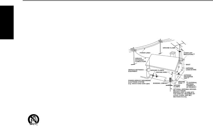
14.Outdoor Antenna Grounding - If an outside antenna or cable system is connected to the product, be sure the antenna or cable system is grounded so as to provide some protection against voltage surges and built-up static charges. Article 810 of the National Electrical Code, ANSI/NFPA 70, provides information with regard to proper grounding of the mast and supporting structure, grounding of the lead-in wire to an antenna discharge unit, size of grounding conductors, location of antenna discharge unit, connection to grounding electrodes, and requirements for the grounding electrode.
NOTE TO CATV SYSTEM INSTALLER
ThisreminderisprovidedtocalltheCATVsysteminstaller’sattentiontoSection820-40 oftheNECwhichprovidesguidelinesforpropergroundingand,inparticular,specifies thatthecablegroundshallbeconnectedtothegroundingsystemofthebuilding,as closetothepointofcableentryaspractical.
15.Lightning - For added protection for this product during a lightning storm, or when it is left unattended and unused for long periods of time, unplug it from the wall outlet and disconnect the antenna or cable system. This will prevent damage to the product due to lightning and power-line surges.
16.Power Lines - An outside antenna system should not be located in the vicinity of overhead power lines or other electric light or power circuits, or where it can fall into such power lines or circuits. When installing an outside antenna system, extreme care should be taken to keep from touching such power lines or circuits as contact with them might be fatal.
17.Overloading - Do not overload wall outlets, extension cords, or integral convenience receptacles as this can result in a risk of fire or electric shock.
18.Flame Sources - No naked flame sources, such as lighted candles, should be placed on the product.
19.Object and Liquid Entry - Never push objects of any kind into this product through openings as they may touch dangerous voltage points or short-out parts that could result in a fire or electric shock. Never spill liquid of any kind on the product.
20.Headphones - Excessive sound pressure form earphones and headphones can cause hearing loss.
21.Damage Requiring Service - Unplug this product from the wall outlet and refer servicing to qualified service personnel under the following conditions:
a.When the power-supply cord or plug is damaged.
b.If liquid has been spilled, or objects have fallen into the product.
c.If the product has been exposed to rain or water.
d.If the product does not operate normally by following the operating instructions. Adjust only those controls that are covered by the operating instructions as an improper adjustment of other controls may result in damage and will often require extensive work by a qualified technician to restore the product to its normal operation.
e.If the product has been dropped or damaged in any way.
f.When the product exhibits a distinct change in performance-this indicates a need for service.
22.Replacement Parts - When replacement parts are required, be sure the service technician has used replacement parts specified by the manufacturer or have the same characteristics as the original part. Unauthorized substitutions may result in fire, electric shock, or other hazards.
2
IMPORTANT SAFETY INSTRUCTIONS
23.Battery Disposal - When disposing of used batteries, please comply with governmental regulations or environmental public instruction’s rules that apply in your country or area.
24.Safety Check - Upon completion of any service or repairs to this product, ask the service technician to perform safety checks to determine that the product is in proper operating condition.
WARNING
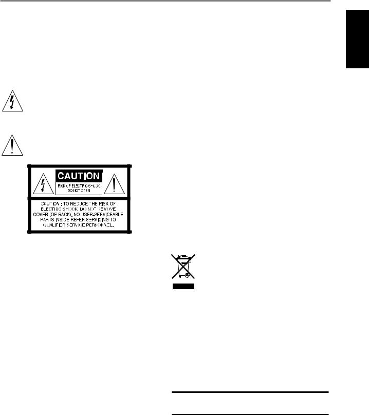
The lightning flash with arrowhead symbol, within an equilateral triangle, is intended to alert the user to the presence of uninsulated “dangerous voltage” within the product’s enclosure that may be of sufficient magnitude to constitute a risk of electric shock to persons
The exclamation point within an equilateral triangle is intended to alert the user to the presence of important operating and maintenance (servicing) instructions in the literature accompanying the appliance.
THE EQUIPMENT MUST BE CONNECTED TO AN EARTHED MAINS SOCKET-OUTLET.
CAUTION REGARDING PLACEMENT
To maintain proper ventilation, be sure to leave a space around the unit (from the largest outer dimensions including projections) than is equal to, or greater than shown below.
Left and Right Panels: 10 cm Rear Panel: 10 cm
Top Panel: 10 cm
FCC STATEMENT
This equipment has been tested and found to comply with the limits for Class B digital device, pursuant to Part 15 of the FCC Rules. These limits are designed to provide reasonable protection against harmful interference in a residential installation. This equipment generates, uses, and can radiate radio frequency energy and, if not installed and used in accordance with the instructions, may cause harmful interference to radio communications. However, there is no guarantee that interference will not occur in a particular installation. If this equipment does cause harmful interference to radio or television reception, which can be determined by turning the equipment off and on, the user is encouraged to try to correct the interference by one or more of the following measures:
•Reorient or relocate the receiving antenna.
•Increase the separation between the equipment and receiver.
•Connect the equipment into an outlet on a circuit different from that to which the receiver is connected.
•Consult the dealer or an experienced radio TV technician for help.
CAUTION
•Changes or modifications to this equipment not expressly approved by NAD Electronics for compliance could void the user’s authority to operate this equipment.
•To prevent electric shock, match wide blade of plug to wide slot, fully insert.
•Danger of explosion if battery is incorrectly replaced. Replace only with the same or equivalent type.
•An appliance with a protective earth terminal should be connected to a mains outlet with a protective earth connection.
WARNING
•To reduce the risk of fire or electric shock, do not expose this apparatus to rain or moisture.
•The apparatus shall not be exposed to dripping or splashing and that no objects filled with liquids, such as vases, shall be placed on apparatus.
•Mains plug is used as disconnect device and it should remain readily operable during intended use. In order to disconnect the apparatus from the mains completely, the mains plug should be disconnected from the mains socket outlet completely.
•Battery shall not be exposed to excessive heat such as sunshine, fire or the like.
IF IN DOUBT CONSULT A COMPETENT ELECTRICIAN.
This product is manufactured to comply with the radio interference requirements of EEC DIRECTIVE 2004/108/EC.
NOTES ON ENVIRONMENTAL PROTECTION
At the end of its useful life, this product must not be disposed of with regular household waste but must be returned to a collection point for the recycling of electrical and electronic equipment. The symbol on the product, user’s manual and packaging point this out.
The materials can be reused in accordance with their markings. Through re-use, recycling of raw materials, or other forms of recycling of old products, you are making an important contribution to the protection of our environment.
Your local administrative office can advise you of the responsible waste disposal point.
RECORD YOUR MODEL NUMBER (NOW, WHILE YOU CAN SEE IT)
The model and serial number of your new T 778 are located on the back of the cabinet. For your future convenience, we suggest that you record these numbers here:
Model number : . . . . . . . . . . . . . . . . . . . . . . . . . . . . . . . . . . . . . .
Serial number :. . . . . . . . . . . . . . . . . . . .
ENGLISH
NAD is a trademark of NAD Electronics International, a division of Lenbrook Industries Limited Copyright 2020, NAD Electronics International, a division of Lenbrook Industries Limited
3

ENGLISH
INTRODUCTION
TABLE OF CONTENTS
IMPORTANT SAFETY INSTRUCTIONS . . . . . . . . . . . . . . . . . . . . . . . . . .2
INTRODUCTION
GETTING STARTED. . . . . . . . . . . . . . . . . . . . . . . . 5
WHAT’S IN THE BOX. . . . . . . . . . . . . . . . . . . . . . . . . .5 CHOOSING A LOCATION .. . . . . . . . . . . . . . . . . . . . . . 5 DEFAULT SOURCE SETTINGS . . . . . . . . . . . . . . . . . . . . . 5
IDENTIFICATION OF CONTROLS |
|
FRONT PANEL.. . . . . . . . . . . . . . . . . . . . . . . . . . 6 |
|
REAR PANEL . . . . . . . . . . . . . . . . . . . . . . . . . . . |
7 |
OPERATION |
|
CONFIGURING T 778 - MAIN MENU VIA ON-SCREEN DISPLAY. . . |
. 9 |
MAIN MENU . . . . . . . . . . . . . . . . . . . . . . . . . . . . |
. 9 |
DSP OPTIONS . . . . . . . . . . . . . . . . . . . . . . . . . . . . |
.9 |
TONE CONTROLS.. . . . . . . . . . . . . . . . . . . . . . . . . . |
9 |
ZONE CONTROLS. . . . . . . . . . . . . . . . . . . . . . . . . . . . . . . . . . . . . . . . . . . . . . . . . . . |
10 |
SYSTEM INFO . . . . . . . . . . . . . . . . . . . . . . . . . . . . |
11 |
CONFIGURING T 778 - SETUP MENU VIA ON-SCREEN DISPLAY . . . |
12 |
SETUP MENU . . . . . . . . . . . . . . . . . . . . . . . . . . . . |
12 |
CONTROL SETUP . . . . . . . . . . . . . . . . . . . . . . . . . . . . . . . . . . . . . . . . . . . . . . . . . . . |
12 |
IR CHANNEL.. . . . . . . . . . . . . . . . . . . . . . . . . . . . |
13 |
SOURCE SETUP . . . . . . . . . . . . . . . . . . . . . . . . . . . |
13 |
SPEAKER SETUP . . . . . . . . . . . . . . . . . . . . . . . . . . |
15 |
SPEAKER CONFIGURATION . . . . . . . . . . . . . . . . . . . . . . . . . . . . . . . . . . . . . . . . . |
15 |
SPEAKER LEVELS. . . . . . . . . . . . . . . . . . . . . . . . . . |
15 |
SPEAKER DISTANCE . . . . . . . . . . . . . . . . . . . . . . . . . |
16 |
DIRAC LIVE. . . . . . . . . . . . . . . . . . . . . . . . . . . . . |
16 |
ADJUSTING THE VOLUME . . . . . . . . . . . . . . . . . . . . . . |
18 |
ADJUSTING CHANNEL LEVELS “ON THE FLY”.. . . . . . . . . . . . |
18 |
ZONE SETUP . . . . . . . . . . . . . . . . . . . . . . . . . . . . |
18 |
AMPLIFIER SETUP . . . . . . . . . . . . . . . . . . . . . . . . . . |
19 |
TRIGGER SETUP . . . . . . . . . . . . . . . . . . . . . . . . . . . |
19 |
LISTENING MODE SETUP . . . . . . . . . . . . . . . . . . . . . |
19 |
LISTENING MODES . . . . . . . . . . . . . . . . . . . . . . . . |
20 |
DOLBY SETUP. . . . . . . . . . . . . . . . . . . . . . . . . . . . |
21 |
DTS SETUP .. . . . . . . . . . . . . . . . . . . . . . . . . . . . |
21 |
ENHANCED STEREO. . . . . . . . . . . . . . . . . . . . . . . . . |
21 |
FRONT PANEL DISPLAY SETUP. . . . . . . . . . . . . . . . . . . |
21 |
A/V PRESETS. . . . . . . . . . . . . . . . . . . . . . . . . . . . |
23 |
SYSTEM AND UPGRADE. . . . . . . . . . . . . . . . . . . . . . . |
26 |
SELECT LANGUAGE. . . . . . . . . . . . . . . . . . . . . . . . . . . . . . . . . . . . . . . . . . . . . . . . . |
26 |
MASTER QUALITY AUTHENTICATED. . . . . . . . . . . . . . . . . |
26 |
CONFIGURING T 778 - MENU VIA FRONT PANEL DISPLAY. . . . . |
27 |
MENU OPTIONS . . . . . . . . . . . . . . . . . . . . . . . . . . . . . . . . . . . . . . . . . . . . . . . . . . . . |
27 |
MAKING THE MOST OUT OF YOUR BluOS SOURCE. . . . . . . . . |
29 |
USING THE HTR 8 REMOTE CONTROL . . . . . . . . . . . . . . . |
30 |
OVERVIEW OF THE HTR 8. . . . . . . . . . . . . . . . . . . . . . |
30 |
GETTING FAMILIAR WITH THE HTR 8.. . . . . . . . . . . . . . . . |
30 |
LEARNING CODES FROM OTHER REMOTES.. . . . . . . . . . . . |
30 |
PUNCH THROUGH. . . . . . . . . . . . . . . . . . . . . . . . . |
31 |
COPY A COMMAND FROM ANOTHER KEY.. . . . . . . . . . . . . |
31 |
MACRO COMMANDS. . . . . . . . . . . . . . . . . . . . . . . |
31 |
KEY ILLUMINATION TIMEOUT.. . . . . . . . . . . . . . . . . . . |
32 |
CONFIGURING KEY ILLUMINATION. . . . . . . . . . . . . . . . |
32 |
FACTORY RESET. . . . . . . . . . . . . . . . . . . . . . . . . . . |
32 |
DELETE MODE. . . . . . . . . . . . . . . . . . . . . . . . . . . |
32 |
LOADING CODE-LIBRARIES. . . . . . . . . . . . . . . . . . . . . |
33 |
SEARCH MODE. . . . . . . . . . . . . . . . . . . . . . . . . . . |
33 |
CHECKING CODE-LIBRARY NUMBER. . . . . . . . . . . . . . . . |
33 |
SUMMARY OF THE HTR 8 MODES . . . . . . . . . . . . . . . . . . |
33 |
USB INTERFACE. . . . . . . . . . . . . . . . . . . . . . . . . . |
34 |
USING THE ZR 7 REMOTE CONTROL. . . . . . . . . . . . . . . . . |
34 |
REFERENCE
SPECIFICATIONS. . . . . . . . . . . . . . . . . . . . . . . . .35
4

WHAT’S IN THE BOX
Packed with your T 778 you will find
•Quick Setup Guide
•BluOS Kit containing USB Hub, Wi-Fi Dongle, Bluetooth USB Micro Adapter and USB to USB Cable Extender
•HTR 8 remote control with 4 AA batteries
•ZR 7 zone remote control with 3V CR2025 battery
•Mic Assembly with Ferrite Base
•USB MIC Sound Adaptor
•Detachable mains power cord
NOTE
Follow supplied Quick Setup Guide to help you get started with your T 778.
SAVE THE PACKAGING
Please save the box and the packaging that came with the T 778. Should you move or need to transport your T 778, this is the safest container to use. We’ve seen too many otherwise perfect components damaged in transit for lack of a proper shipping carton. So please, save that box!
CHOOSING A LOCATION
Choose a location that is well ventilated (with at least several inches to both sides and behind), and that will provide a clear line of sight, within 25 feet/8 meters, between the T 778’s front panel and your primary
listening/viewing position—this will ensure reliable infrared remote control communications. The T 778 generates a modest amount of heat, but nothing that should trouble adjacent components.
DEFAULT SOURCE SETTINGS
The following table lists the default SOURCE settings. Note that the Audio input settings show both digital and analog audio input. Digital input will always take precedence over analog audio input even if both are present.
SOURCE |
AUDIO INPUT |
VIDEO INPUT |
Source 1 |
HDMI 1/Audio 1 |
HDMI 1 |
Source 2 |
HDMI 2/Audio 2 |
HDMI 2 |
Source 3 |
HDMI 3 |
HDMI 3 |
Source 4 |
HDMI 4 |
HDMI 4 |
Source 5 |
HDMI 5 |
HDMI 5 |
Source 6 (BluOS) |
BluOS |
BluOS |
Source 7 (Phono) |
Phono |
Off |
Source 8 (Front Input) |
HDMI Front |
HDMI Front |
|
|
|
To modify the above default settings and for a better understanding of source setting and combinations, please refer to the item about “SOURCE SETUP” in the “CONFIGURING T 778 - SETUP MENU VIA ON-SCREEN DISPLAY” segment of the “OPERATION” section.
INTRODUCTION
GETTING STARTED
ENGLISH
5

IDENTIFICATION OF CONTROLS
FRONT PANEL
ENGLISH
1 |
2 |
3 |
4 |
5 |
6 |
1STANDBY LED
•This indicator will light up amber when the T 778 is at standby mode.
•When T 778 is powered up from standby mode, this indicator will illuminate blue.
•If Zone 2 is ON and STANDBY button is pressed to switch the T 778 to standby mode, the front panel display will be extinguished but the STANDBY LED remains illuminated blue. This indicates Zone 2 is still active.
•In order to completely shut down the T 778 with Zone 2 still ON, press and hold STANDBY button until the STANDBY LED turns amber.
•When infrared command from the HTR 8 is received, this indicator will also flash momentarily.
2STANDBY BUTTON
•Press this button to switch ON the T 778 from standby mode. The Standby LED indicator will turn from amber to blue and illuminate the front panel display. Pressing the STANDBY button again turns the unit back to standby mode.
NOTE
In order to turn ON the T 778 from standby mode or back to standby mode, the rear panel POWER switch must be in the ON position.
3DISPLAY (TOUCH PANEL DISPLAY)
•Display visual information about current music or media source, settings or menu options.
•Touch control functions are also displayed depending upon menu option selected.
•Send out remote control commands by directing or pointing HTR 8 towards the display panel.
4FRONT USB INPUT
•Connect to this Front Input port USB mass storage devices formatted as FAT32, NTFS or Linux ext4. The connected USB device appears as a Local Source (USB) in the BluOS App.
•Access and playback music stored in the connected USB device by selecting “USB” from the BluOS App.
5FRONT HDMI INPUT
•Use the Front HDMI Input to connect directly a HDMI output source.
6VOLUME
•The VOLUME control adjusts the overall loudness of the signal driving the loudspeakers or headphones.
•Turn clockwise to increase the volume level; counter clockwise to lower it.
6

IDENTIFICATION OF CONTROLS
REAR PANEL
1 |
2 |
3 |
4 |
5 |
6 |
7 |
8 |
9 |
10 |
11 |
ENGLISH |
|
|
|
|
|
|
|
|
|
|
|
|
12 |
|
|
|
|
|
|
|
|
|
13 |
14 |
1HDMI (HDMI 1-5, HDMI 1-2 OUT)
•Connect HDMI 1-5 to various HDMI OUT connectors of source components such as DVD player, BD player, HDTV satellite/cable box and other applicable types of equipment.
•Connect HDMI 1-2 OUT to HDTVs or projectors with HDMI input. HDMI 1 OUT supports 4K@60 4:4:4 and HDCP 2.2 compliant. Both HDMI output ports display simultaneously the same audio/video source.
WARNING
Before connecting and disconnecting any HDMI cables, both the T 778 and the ancillary source must be powered OFF and unplugged from the AC outlet. Failure to observe this practice may cause permanent damage to all types of equipment connected via HDMI sockets.
2ETHERNET/LOCAL AREA NETWORK (LAN) PORT
•LAN connection must be setup for wired connection to be established. Set up a Wired Ethernet broadband router with broadband internet connection. Your router or home network should have a built-in DHCP server to consummate the connection.
•Using a standard straight-through Ethernet cable (not supplied), connect one end of the Ethernet cable to the LAN port of your wired Ethernet broadband router and the other end to T 778’s LAN port.
•This Ethernet connection has similar function as that of the RS232 connection. With your PC and the T 778 on the same network,
it allows remote control of the T 778 via compatible external controllers.
NOTES
•NAD is not responsible for any malfunction of the T 778 and/or the internet connection due to communication errors or malfunctions associated with your broadband internet connection or other connected equipment. Contact your Internet Service Provider (ISP) for assistance or the service bureau of your other equipment.
•Contact your ISP for policies, charges, content restrictions, service limitations, bandwidth, repair and other related issues pertinent to internet connectivity.
USB
•Connect the USB connector of the supplied BluOS/USB hub to this USB input. Ensure that the Wi-Fi dongle and Bluetooth USB Micro Adaptor are securely connected to any of the 4 ports of the USB hub. If wireless connectivity is poor, connect Wi-Fi dongle to the supplied extension cable and straighten out for better reception.
•Refer also to instructions on HOW TO SETUP WIRELESS CONNECTION in the BluOS SETUP menu.
3DIGITAL AUDIO IN (COAXIAL 1-2, OPTICAL 1-2)
•Connect to corresponding optical or coaxial digital output of sources such as CD or BD/DVD players, digital cable box, digital tuners and other applicable types of equipment.
•Coaxial and optical digital input association is configurable via the Source Setup item of the Setup Menu.
HT 2/SURR-B HT 1/SURR-B
•Connect HT 2/SURR-B and/or HT 1/SURR-B to the audio input of an external power amplifier hooked up with up to 4 Height speakers.
4AUDIO 1-2
•Input for line level sources such as CD player, tuner or any compatible devices. Use dual RCA-to-RCA cable to connect the source device’s left and right “Audio Output” to these line input ports.
5PHONO
•Input for a Moving Magnet (MM) phono cartridge only. Connect twin RCA-to-RCA lead from your turntable to this input if you are using a Moving Magnet cartridge.
•If your turntable includes a ground/earth lead, it can be connected to the Ground Terminal (item 8).
6ZONE 2
•Send zone selected audio source to the corresponding audio input of a separately located additional amplifier or receiver (not supplied) that can power its matching set of speakers.
•Use high quality patch cables to reduce noise pickup over long distance runs.
7

ENGLISH
IDENTIFICATION OF CONTROLS
REAR PANEL
7AUDIO PRE-OUT (FRONT L, FRONT R, CENTER, SURR R, SURR L, SURR-BL, SURR-BR, SUBW1, SUBW2)
•AUDIO PREOUT makes it possible to use the T 778 as a preamplifier to external power amplifiers for some or all channels.
•Connect FRONT L, FRONT R, CENTER, SURR R, SURR L, SURR-BL and SURR-BR to the respective channel input of a power amplifier or amplifiers driving the corresponding applicable speakers.
•Connect SUBW1 (and/or SUBW2) output to powered (“active”) subwoofers or to power amplifier channels driving a passive system.
•Unlike the full range channels, there is no power amplifier built-into the T 778 for a subwoofer.
8GROUND TERMINAL
•Use this ground terminal to connect to ground a phono or turntable source for PHONO input.
•Unscrew the terminal and insert into the hole the single wire earth lead that is normally included with turntables. Tighten the terminal to secure the lead.
9+12V TRIGGER OUT
•The T 778 has three +12V TRIGGER OUT ports (OUT 1, OUT2 and OUT3) that can be configured to supply +12V DC to a linked component or system. See discussion on “Trigger Setup” at the “Setup Menu” literature for guidelines on how to configure +12V TRIGGER IN/OUT.
•Use a 3.5mm mini-jack connector to pass +12 volts at a maximum current of 50 milliamps to auxiliary equipment such as multichannel amplifier or subwoofer. The center conductor (hot) of the 3.5mm jack is the control signal. The outside conductor (shield) is the ground return-path.
•This output will be 12V when the T 778 is ON and 0V when the unit is either OFF or in standby mode.
+12V TRIGGER IN
•With this input triggered by a 12V DC supply, the T 778 can be switched ON remotely from standby mode by compatible devices such as amplifiers, preamplifiers, receivers, etc. If the 12V DC supply is cut off, the T 778 will return to standby mode.
•Connect this +12V Trigger input to the remote device’s corresponding +12V DC output jack using a mono cable with 3.5mm male plug. The controlling device must be equipped with a +12V trigger output to use this feature.
10RS 232
•NAD is an integration partner with several smart control and automation systems like Control4, Crestron, LUTRON among others. Check out NAD website for a list of NAD’s integration partners. See your NAD audio specialist for more information.
•Connect this interface using RS-232 serial cable (not supplied) to any Windows compatible PC to allow remote control of T 778 via compatible external controllers.
•Refer to NAD website for information about RS232 Protocol documents and PC interface program.
•Use this port also for firmware upgrade. Instructions on how to use this port for firmware upgrade is included in the firmware upgrade (if any) procedure available from the NAD website.
11IR IN/IR OUT 1-3
•These mini-jacks accept and output remote-controlled codes in electrical format, using industry-standard protocols, for use with “IR-repeater” and multi-room systems and related technologies.
•All NAD products with IR IN/IR OUT features are fully compatible with T 778.
IR IN
•This input is connected to the output of an IR (infrared) repeater (Xantech or similar) or the IR output of another compatible device to allow control of the T 778 from a remote location.
IR OUT 1, IR OUT 2
•Connect IR OUT 1 (and/or IR OUT 2) to the IR IN jack of a compatible device.
•Command and control the linked compatible device by directing its own remote control to T 778’s infrared receiver.
IR IN and IR OUT 1, IR OUT 2, IR OUT 3
•Connect the T 778’s IR IN to the IR OUT of a compatible device. Connect also the T 778’s IR OUT 1 (and/or IR OUT 2, IR OUT 3) to the IR IN of a compatible device.
•With this setup, the T 778 acts as an “IR-repeater” allowing the device connected to the T 778’ s IR IN control or command of the other device linked to T 778’s IR OUT 1 (and/or IR OUT 2, IR OUT 3).
IR OUT 3
•IR OUT 3 can only function as an “IR-repeater” as described above.
12SPEAKERS
•Connect SPEAKER’s FRONT L, FRONT R, CENTER, SURR R, SURR L, SURR-BL, SURR-BR, HT 1R and HT 1L channels to their corresponding loudspeakers. Make sure the “+” (red) terminal and “-”(black) terminal are connected to the corresponding “+” and “-”terminals of the loudspeaker. Use extra care to ensure that no stray wires or strands cross between posts or terminals at either end.
•The T 778 is designed to produce optimum sound quality when connected to speakers with impedances within its operating range. Please make sure that all the speakers are rated 4 ohms minimum per speaker.
13AC MAINS INPUT
•The T 778 comes supplied with two separate mains power cords. Select the mains power cord appropriate for your region.
•Before connecting the power cord’s plug to the mains power outlet, ensure that the other end of the power cord is firmly connected to T 778’s AC Mains input socket.
•Always unplug the power cord from the mains power outlet before disconnecting the other end of the power cord from T 778’s AC Mains input socket.
14POWER
•The POWER switch controls the supply of AC mains power to T 778.
•When the POWER switch is set to ON position, the T 778 goes to standby mode as shown by the amber status condition of the Standby LED. Press the front panel Standby button or HTR 8 remote control’s [ON] button to switch ON the T 778 from standby mode.
•If you intend not to use the T 778 for long periods of time (such as when on vacation), switch off the POWER switch.
•With POWER switched off, neither the front panel Standby button nor HTR 8 remote control’s [ON] button can activate the T 778.
8

OPERATION
CONFIGURING T 778 - MAIN MENU VIA ON-SCREEN DISPLAY
The T 778 can be setup or configured using either of the following two methods
•On-Screen-Display (OSD)
•Touch Screen Front Panel Display
The T 778 employs a simple, self-explanatory system of on-screen display “menus” that will appear on the connected video monitor/TV. These are required during the setup process (and are useful in day-to-day operation), so be sure to connect the monitor/TV before proceeding with setup.
DISPLAY THE OSD
Press [S], [MENU] or [ENTER] buttons of the HTR 8 remote control to display the T 778’s Main Menu on your video monitor/TV. If the OSD does not appear, check your HDMI OUT connections.
IMPORTANT
The OSD can only be viewed using a display device with minimum 1080p resolution.
NAVIGATING THE OSD AND MAKING CHANGES
Undertake the following guidelines to navigate through the OSD menu options using the HTR 8 remote control.
1Press [S] to select a menu item. Use [D/F] or in some cases, [ENTER], to move up or down the Menu selections. Repeatedly press [S] to advance or go further into the sub-menu of desired menu item.
2Use [D/F] to set or change the parameter value (setting) of a menu item.
3Press [A] to save the settings or changes done on the current menu or sub-menu. Pressing [A] will also return the user to the previous menu or exit from a particular menu.
MAIN MENU
The Main Menu contains menu options for “DSP Options”, “Tone Controls”, “Zone Controls”, “System Info” and access to “Setup Menu”.
Follow the guidelines about “DISPLAY THE OSD” and “NAVIGATING THE OSD AND MAKING CHANGES” to navigate through the menu options and their sub-menu selections.
NOTE
The individual configurations set forth at “DSP Options” and “Tone Controls” are carried over whenever they are enabled at A/V Presets setting. Refer also to the section about “A/V PRESETS”.
DSP OPTIONS
The following signal processing parameters can be setup under the DSP (Digital Signal Processing) Options menu.
LIP SYNC DELAY
DSP Options has the feature “Lip Sync Delay” whose function is to match any delay that may occur in the picture relative to the audio.
By varying “Lip Sync Delay” from 0ms to 120ms, one can delay the audio output in order to synchronize it with the video image.
TONE CONTROLS
The T 778 has three Tone Control levels – Treble, Bass and Center Dialog. Bass and Treble controls only affect the low bass and high treble leaving the critical midrange frequencies free of coloration. The Center Dialog (“Dialog” in the front panel display) control boosts the “presence” of the midrange region improving intelligibility of speech.
These controls allow one to tweak on-the-fly, the frequency response of the source during playback. The control setting could be adjusted by navigating through the Tone Controls’ OSD menu via a combination of [ENTER] and [A/S/D/F] keys.
Maximum and minimum values for all three Tone Control levels are ±10 dB.
“Tone Defeat” gives one the choice of varying or completely bypassing the tone control section of the T 778. If “Off” (“Tone Active” in the front panel display) is selected, the Tone Control circuits are active.
Select “On” (“Tone Defeat” in the front panel display) to bypass the Tone Controls effectively defeating the effect of the tone control circuits.
NOTE
Tone Controls options can be directly selected or changed using HTR 8’s [TONE] button with DEVICE SELECTOR set to AMP mode. Toggle [TONE] button to select “Treble”, “Bass” or “Dialog” and then use the [D/F] to adjust their respective levels. Press [TONE] again to save the settings and at the same time move on to the next parameter or exit the parameter setting altogether.
ENGLISH
9
ENGLISH
OPERATION
CONFIGURING T 778 - MAIN MENU VIA ON-SCREEN DISPLAY
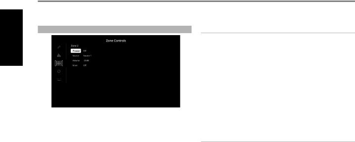
ZONE CONTROLS
Depending on the settings made at the separate “Zone Setup” menu under the “Setup Menu” section discussion, Zone 2 can be configured and managed via this “Zone Controls” window.
Set “Power” to “On” to activate Zone 2. When activated, the Source input for Zone 2 can be allocated by selecting through the following inputs - Source 1, Source 2, Phono and Local.
As long as the associated Source input is active, it will continuously be available at ZONE 2 output port in the rear panel regardless of the Main Zone settings. For example, while the T 778 is at Source 1 mode, you can set the Zone 2 Controls’“Source” item to “Source 2”; the active Source 2’s audio output will be directed to ZONE 2 output port in the rear panel even though the T 778 is at Source 1 mode.
You can then feed ZONE 2 output using applicable connector cables (not supplied) to another amplifier or receiver that maybe located in another area of your home. With your separate amplifier or receiver selecting the fed signal and with speakers connected, you can then enjoy the zone selected source’s audio signal.
Select “Local” as your selected Zone 2 Source input if you wish to enjoy the same source as the main Zone and allow simultaneous listening, but with full separate volume levels.
If Zone 2 “Power” is set to “Off”, it is deactivated or powered off.
ZONE 2 AT AUDIO PRE-OUT SURROUND BACK
SURR-BL and SURR-BR channels of AUDIO PRE-OUT can be assigned as Zone 2 OUT. This is applicable only if “Zone 2” is the selected setting of “Back Amplifier” in the “Amplifier Setup” menu.
With this condition, the following are applicable
•The surround back amplifier channels supply Zone 2 speaker level output via the surround back speaker terminals. With this setup, Zone 2 audio/speaker level can be increased or decreased using the VOL (Volume) keys of the supplied ZR 7 zone remote control.
•At the same time, Zone 2 continues to send zone selected audio source to the corresponding audio input of a separately located additional amplifier or receiver (not supplied) that can power its matching set of speakers. Zone 2 audio level for this port is fixed; it cannot be adjusted by any ZR 7 volume command.
•Zone 2 audio level can only be adjusted using the Volume keys of ZR 7 remote control only if “Back Amplifier” in the “Amplifier Setup” menu is set to “Zone 2”.
IMPORTANT NOTICE
•Only analog audio connected through a Source’s analog audio input port can be associated as audio source for Zone 2.
•Digital audio sources connected via HDMI, digital optical and digital coaxial input ports cannot be downmixed and used as Zone 2 audio source.
•BluOS audio is also not applicable as a Zone 2 audio source.
VOLUME
“Volume” refers to the adjustable secondary Zone 2 Volume level that can be increased or decreased depending upon its settings. This is applicable only if the Zone 2 Volume setting in the separate “Zone Setup” menu under “Setup Menu” is set to “Variable”. If set to “Fixed”, this “Volume” item at the Zone Controls section will not be available.
NOTES
•If Zone 2 is still ON and STANDBY button is pressed to switch the front panel display to standby mode, the front panel display will be extinguished but the STANDBY LED remains illuminated blue. This
indicates that Zone 2 is still active. In order to completely shut down the front panel display together with Zone 2, press and hold front panel STANDBY button until the STANDBY LED turns amber.
•Zone 2 is audio only and not associated with any video input sources.
10
OPERATION
CONFIGURING T 778 - MAIN MENU VIA ON-SCREEN DISPLAY
SYSTEM INFO |
TEMPERATURE |
ENGLISH
“System Info” displays information about current firmware versions of MCU, DSP, Video and BluOS/ OSD as well the unit’s serial number, IP address, Temperature and Fan speed. The System Information shown above is for reference only.
CHECK FOR UPGRADE
Your T 778 is updated to latest firmware versions if “Check for Upgrade” is shown.
SYSTEM INFO (*)
Your T 778 needs to be updated if the “System Info” item in the Main Menu changes to “System Info*”. The “*” beside “System Info*” indicates that there is Software Upgrade available for your T 778. Select “System Info*” to initiate the upgrade process.
START UPGRADE
With your T 778 connected to internet, select “Start Upgrade” and Internet Update will proceed automatically.
Refer also to enclosed INTERNET UPDATE GUIDELINES for further guidelines.
Temperature readings are displayed as measured over Front, Center, Surround, Back, Height and PSU channels.
FAN
Fan speed and fan status are displayed.
11
Loading...