


2000
SPLIT-TYPE,HEAT PUMP AIR CONDITIONERS
No. OC220
TECHNICAL & SERVICE MANUAL
Series PMFY Ceiling Cassettes R407C 

 R22
R22
Indoor unit |
|
[Model names] |
[Service Ref.] |
PMFY-P20VBM
PMFY-P25VBM
PMFY-P32VBM
PMFY-P40VBM
PMFY-P20VBM PMFY-P25VBM PMFY-P32VBM PMFY-P40VBM
CONTENTS
1. SAFETY PRECAUTION ·······················2
2. PART NAMES AND FUNCTIONS ········4
3. SPECIFICATION ···································6
4. OUTLINES AND DIMENSIONS··········10
5. WIRING DIAGRAM ·····························11
6. REFRIGERANT SYSTEM DIAGRAM ···12
7. TROUBLE SHOOTING·······················13
8. DISASSEMBLY PROCEDURE···········19
9. PARTS LIST········································22
INDOOR UNIT

1 
 SAFETY PRECAUTION
Cautions for devices that use R407C refrigerant.
·Do not use the existing refrigerant piping.
-The old refrigerant and refrigerator oil in the existing piping contains a large amount of chlorine which may cause the refrigerator oil of the new unit to deteriorate.
·Use “low residual oil piping”.
-If there is a large amount of residual oil (hydraulic oil, etc.) inside the piping and joints, deterioration of the refrigerator oil will result.
·Store the piping to be used during installation indoors and keep both ends of the piping sealed until just before brazing. (Store elbows and other joints in a plastic bag.)
-If dust, dirt, or water enters the refrigerant cycle, deterioration of the oil and compressor trouble may result.
·Use Suniso 4GS or 3GS (small amount) as the refrigerator oil to coat flares and flange connection parts.
-The refrigerator oil used with the air conditioner is highly hygroscopic. If it is used, water may be mixed in and deterioration of the refrigerator oil may result.
·Use liquid refrigerant to seal the system.
-If gas refrigerant is used to seal the system, the composition of the refrigerant in the cylinder will change and performance may drop.
·Do not use a refrigerant other than R407.
-If another refrigerant (R22, etc.) is used, the chlorine in the refrigerant may cause the refrigerator oil to deteriorate.
·Use a vacuum pump with a reverse flow check valve.
-The vacuum pump oil may flow back into the refrigerant cycle and cause the refrigerator oil to deteriorate.
2

[1] Service tools
Use the below service tools as exclusive tools for R407C refrigerant.
No. |
Tool name |
Specifications |
1 |
Gauge manifold |
·Only for R407C. |
|
|
·Use the existing fitting SPECIFICATIONS. (UNF7/16) |
|
|
·Use high-tension side pressure of 35kgf/cm or over. |
|
|
2 |
2 |
Charge hose |
·Only for R407C. |
|
|
·Use pressure performance of 52kgf/cm or over. |
3 |
Electronic scale |
|
4 |
Gas leak detector |
·Use the detector for R134a or R407C. |
5 |
Adapter for reverse flow check. |
·Attach on vacuum pump. |
6 |
Refrigerant charge base. |
|
7 |
Refrigerant cylinder. |
·For R407C·Top of cylinder (Brown) |
|
|
·Cylinder with syphon |
8 |
Refrigerant recovery equipment. |
|
[2] Notice on repair service
·After recovering the all refrigerator in the unit, proceed to working. ·Do not release the refrigerant in the air.
·After complete the repair service, recharge the cycle with the specified amount of the liquid refrigerant.
[3] Refrigerant recharging
(1) Refrigerant recharging process
1Direct enclosure from the bomb.
·Confirm that R407C bomb on the market are syphon pipe.
·Leave the syphon pipe bomb raising and recharge it. (By liquid refrigerant)
Unit
Gravimeter
(2) Recharge in refrigerant leakage case
·After recovering the all refrigerator in the unit, proceed to working. ·Do not release the refrigerant in the air.
·After complete the repair service, recharge the cycle with the specified amount of the liquid refrigerant.
3

2 
 PART NAMES AND FUNCTIONS
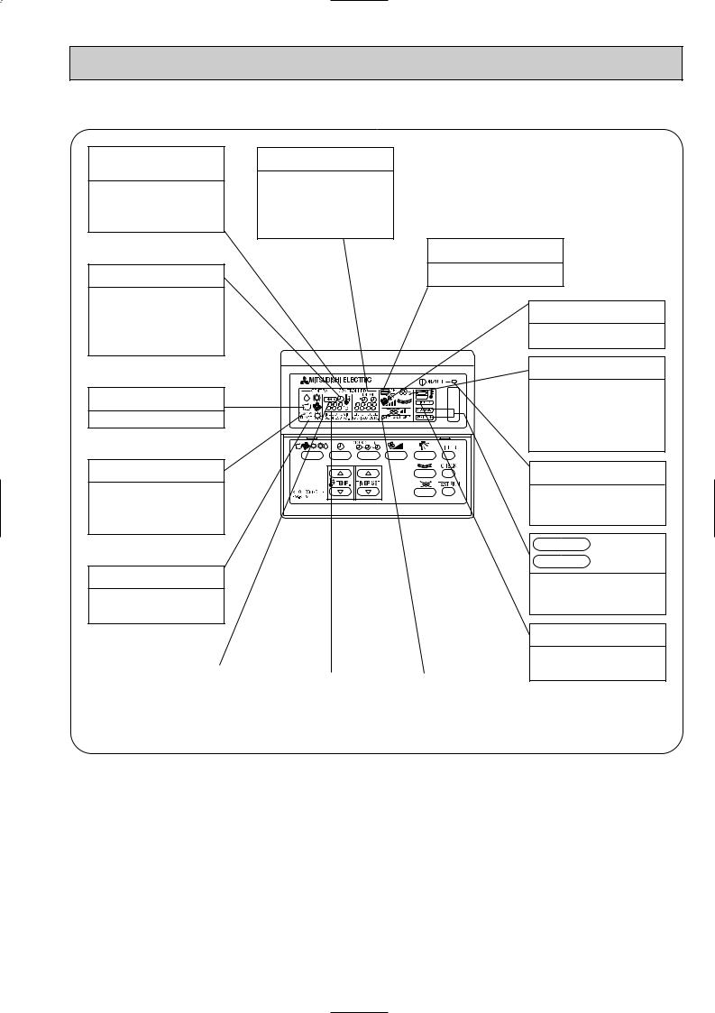
● Indoor (Main) Unit
Auto Air Swing Vane
Disperses airflow up and down and adjusts the angle of airflow direction.
Horizontal Air Outlet
Guide vane
Air flow can be changed to horinzontally
by moving the Guide vane to the left or right.
Filters |
Air intake |
Remove dust and pollutants |
Inhales air from room. |
from inhaled air. |
|
● Remote controller |
[PAR-F25MA] |
|
● Once the controls are set, the same operation mode can |
|
be repeated by simply pressing the ON/OFF button. |
● Operation buttons |
|
TIMER button
This switches between continuous operation and the timer operation.
OPERATION SWITCH button
Press this button to switch the cooler electronic dry (dehumidify) automatic and heater modes.
TIME SETTING button
This sets of switches the current time, start time and stop time.
AIR SPEED button
This sets the ventilation fan speed.
ON/OFF button
This switches between the operation and stop modes each time it is pressed. The lamp on this button lights during operation.
 TEMP. ADJUSTMENT button
This sets the room temperature the temperature setting can be performed in 1: units
Setting range
Cooler 19: to 30: Heater 17: to 28:
LOUVER button
This switch the horizontal fan motion
NO and OFF.
(This button does not operate in this model)
AIR DIRECTION button
This adjusts the vertical angle of the ventilation.
FILTER button
This resets the filter service indication display
CHECK-TEST RUN button
Only press this button to perform an inspection check or test operation. Do not use it for normal operation.
4
● Display
CENTRALLY CONTROLLED display
This indicates when the unit is controlled by optional features such as central control type remote controller.
TIMER display
This indicates when the continuous operation and time operation modes are set.
It also display the time for the timer operation at the same time as when it is set.
OPERATION MODE display
This indicates the operation mode.
STANDBY display
This indicates when the standby mode is set from the time the sleep operation starts until the heating air is discharged.
DEFROST display
This indicates when the defrost operation is performed.
CLOCK display |
In this display example on the bot- |
|
tom left, a condition where all dis- |
||
|
||
The current time , start time and stop |
play lamps light is shown for expla- |
|
time can be displayed in ten second |
nation purposes although this differs |
|
intervals by pressing the time switch |
from actual operation. |
|
button. The start time or stop time is |
||
|
||
always displayed during the timer |
|
|
operation. |
|
|
|
AIR DIRECTION display |
|
|
The selected fan speed is displayed. |
|
|
FAN SPEED display |
|
|
This displays the air direction. |
|
|
ROOM TEMPERATURE display |
|
|
The temperature of the suction air is |
|
|
displayed during operation. The dis- |
|
|
play range is 8° to 39°C. The display |
|
|
flashes 8°C when the actual temper- |
|
|
ature is less than 8° and flashes |
|
|
39°C when the actual temperature is |
|
|
greater than 39°C. |
|
|
Operation lamp |
|
5 |
This lamp lights during operation, |
|
|
goes off when the unit stops and |
|
|
flashes when a malfunction occurs. |
|
|
CHECK MODE |
|
|
display |
|
|
TEST RUN |
|
|
This display lights in the check mode |
|
|
or when a test operation is per- |
|
|
formed. |
CHECK display |
|
|
|
|
|
|
SET TEMPERATURE display |
|
POWER display |
This indicates when a malfunction |
|
|
||
|
|
|
|
|
has occurred in the unit which should |
|
This displays the selected setting |
|
This lamp lights when electricity is |
be checked. |
|
|
||
|
temperature. |
|
supplied to the unit. |
|
|
|
|
||
|
|
|
|
|
Caution
FILTER display
This lamp lights when the filter need to be cleaned.
●Only the Power display lights when the unit is stopped and power supplied to the unit.
●When the central control remote control unit, which is sold separately, is used the ON-OFF button, operation switch button and  TEMP. adjustment button do not operate.
●“NOT AVAILABLE” is displayed when the Air speed button are pressed.This indicates that this room unit is not equipped with the fan direction adjustment function and the louver function.
●When power is turned ON for the first time, it is normal that “H0” is displayed on the room temperature indication (For max. 2minutes). Please wait until this “H0” indication disappear then start the operation.
5

3 
 SPECIFICATION
3-1. Specification
Item
Power
Cooling capacity
Heating capacity
characteristic |
Input |
Cooling |
|
||
|
|
|
|
|
Heating |
|
Current |
Cooling |
|
|
|
Electric |
|
Heating |
factor |
Heating |
|
|
Power |
Cooling |
Exterior (munsell symbol)
Height
Dimensions Width
Depth
Heat exchanger
|
Fan No |
|
F |
Air flow #3 |
|
a |
||
External |
||
n |
||
static pressure |
||
|
Fan motor |
|
|
output |
|
|
Insulator |
Air filter
Gas
Pipe side
dimensions Liquid side
Unit drain pipe size
Noise level #3
Product weight
|
PMFY-P20VBM |
PMFY-P25VBM |
PMFY-P32VBM |
PMFY-P40VBM |
V·Hz |
|
Single phase 220V-240V 50 Hz/220V 60Hz |
|
|
kcal/h |
2,000 |
2,500 |
3,150 |
4,000 |
|
|
|
|
|
kW |
2.3 |
2.9 |
3.7 |
4.7 |
|
|
|
|
|
Btu/h |
7,900 |
9,900 |
12,500 |
15,900 |
kcal/h |
2,250 |
2,800 |
3,550 |
4,500 |
|
|
|
|
|
kW |
2.6 |
3.3 |
4.1 |
5.2 |
|
|
|
|
|
Btu/h |
8,900 |
11,100 |
14,100 |
17,900 |
kW |
0.042 |
0.044 |
0.044 |
0.054 |
kW |
0.042 |
0.044 |
0.044 |
0.054 |
A |
0.20 |
0.21 |
0.21 |
0.26 |
A |
0.20 |
0.21 |
0.21 |
0.26 |
% |
95—88 |
95—87 |
95—87 |
94—87 |
% |
95—88 |
95—87 |
95—87 |
94—87 |
|
-Unit : Galvanized sheets · Standard grills : ABS resin acrylic coating |
Munsell<0.98Y 8.99/0.63> |
||
mm |
|
|
230<30> |
|
mm |
|
854<1,000> |
|
|
mm |
|
395<470> |
|
|
|
|
|
Cross fin |
|
|
|
Line flow fan 1 |
|
|
k/min |
8.7-8.0-7.2-6.5 |
9.3-8.6-8.0-7.3 |
10.7-9.7-8.7-7.7 |
|
Pa |
|
|
0 |
|
kW |
|
|
0.028 |
|
|
|
Polyethylene sheet |
|
|
|
|
PP honeycomb fabric |
|
|
[mm |
|
12.7(1/2") |
|
|
[mm |
|
6.35(1/4") |
|
|
[mm |
|
O.D.25 (PVC pipe VP-20 connectable) |
|
|
dB |
35-33-30-27 |
37-36-34-32 |
39-37-35-33 |
|
kg |
|
14<3.0> |
|
|
|
|
|
|
|
Note 1. |
Rating conditions |
|
|
|
|
Cooling: |
Indoor: |
D.B. 27°C |
W.B. 19.5°C |
|
|
outdoor: |
D.B. 35°C |
|
|
Heating: |
Indoor: |
D.B. 21°C |
|
|
|
outdoor: |
D.B. 7°C |
W.B. 6°C |
Note 2. |
The number indicated in < > is just for the grille. |
|||
Note 3. |
Air flow and the noise level are indicated as High-Middium 1-Middium 2-Low. |
|||
6

3-2. Air capacity taken from outside
PMFY-P·VBM series are possible to be taken air from outside. When taking air from the outside, the duct fan can be used to. The air capacity should be 20% or less of the air flow SPEC(Hi).
250 288.5
90-
4-{2.8
|
|
100 |
|
|
{ |
|
|
108 |
|
|
{ |
|
|
122 |
|
Flesh air intake hole |
Flesh air intake hole |
|
(Knock out) |
(Knock out) |
|
Air flow |
Air capacity taken outside |
|
(Hi) |
|
|
|
|
PMFY-P20VBM |
8.7m3/min |
Max 1.74m3/min |
PMFY-P25VBM |
9.3m3/min |
Max 1.86m3/min |
PMFY-P32VBM |
9.3m3/min |
Max 1.86m3/min |
PMFY-P40VBM |
10.7m3/min |
Max 2.14m3/min |
Interlocking operation method with duct fan (Booster fan)
●Whenever the indoor unit is operating, the duct fun also operates.
(1)Connect the optional multiple remote controller adapter(PAC-SA88HA-E)to the connector CN51 on the indoor controller board.
(2)Drive the relay after connecting the 12V DC relay between the Yellow and Orange connector lines.
(w)Use a relay under 1W.
MB: Electromagnetic switch power relay for duct fan. X: Auxiliary relay (12V DC LY-1F)
|
|
|
Be sure to secure insulation |
~ |
|
|
|
|
|
||
|
|
|
material by tape and such |
|
|
CN51 |
5 |
Green |
|
|
|
on |
|
|
Yellow |
|
|
indoor unit |
|
|
|
|
|
1 |
|
Orange |
|
MB |
|
board |
|
|
|||
|
Connector (5P) |
Red |
|
|
|
|
Package side |
Brown |
|
|
|
|
Multiplr remote |
Installation at site |
|||
|
|
|
|||
|
|
|
|
|
|
|
|
|
controller adapter |
Be sure to secure insulation |
|
Indoor controller board |
|
PAC-SA88HA-E |
material by tape and such |
||
|
|
|
|
||
Distance between indoor controller board and relay must be within 10m.
Multiple remote controller adapter PAC-SA88HA-E
CN51
How to read curves
|
Curve in the |
Duct characteristics |
|
1 |
at site |
|
|
|
left praphs. |
|
|
0 |
|
A |
C |
|
|
||
|
Q |
B |
|
|
|
|
|
2
C A |
E |
Q |
3 |
D |
A |
Q |
Qa |
Q…Planned amount of fresh air intake <m3/min>
A…Static pressure loss of fresh air intake duct system with air flow amount Q <mmAq>
B…Forced static pressure at air condi - tioner inlet with air flow amount Q <mmAq>
C…Static pressure of booster fan with
air flow amount Q |
<mmAq> |
D…Static pressure loss |
increase |
amount of fresh air intake dust system for air flow amount Q
<mmAq> E…Static pressure of indoor unit with
air flow amount Q <mmAq> Qa…Estimated amount of fresh air
intake with out D <m3/min>
Characteristic diagram of air capacity taken from outside of PMFY-P·VBM
(Pa) |
50.0 |
|
|
|
|
|
|
|
|
|
|
|
|
|
|
|
|
|
|
|
|
|
|
||
0.0 |
|
|
|
|
|
|
|
|
|
|
|
|
pressure |
|
|
|
|
|
|
|
|
|
2 intakes |
|
|
|
|
|
|
|
|
|
|
|
|
|
||
|
|
|
|
|
|
|
|
|
|
1 intake |
|
|
Static |
|
|
|
|
|
|
|
|
|
|
|
|
-50.0 |
|
|
|
|
|
|
|
|
|
|
|
|
|
|
|
|
|
|
|
|
|
|
|
|
|
|
-100.0 |
|
|
|
|
|
|
|
|
|
|
|
|
|
|
|
|
|
1.5 |
2.0 |
2.5 |
||||
|
0.0 |
0.5 |
1.0 |
|||||||||
|
|
|
|
|
Air flow (m3/min) |
|
|
|
|
|||
7

3-3. NOISE CRITERION CURVES
PMFY-P20VBM |
|
|
NOTCH |
SPL(dB) |
LINE |
|||
|
|
|
|
|
|
Hi |
35 |
|
|
|
|
|
|
|
Mi1 |
33 |
|
|
|
|
|
|
|
Mi2 |
30 |
|
|
|
|
|
|
|
Lo |
27 |
|
|
90 |
|
|
|
|
|
|
|
BAR |
80 |
|
|
|
|
|
|
|
MICRO |
|
|
|
|
|
|
|
|
|
|
|
|
|
|
|
|
|
0.002 |
70 |
|
|
|
|
|
|
NC-70 |
|
|
|
|
|
|
|
||
dB re |
|
|
|
|
|
|
|
|
|
|
|
|
|
|
|
|
|
LEVEL, |
60 |
|
|
|
|
|
|
|
|
|
|
|
|
|
|
NC-60 |
|
|
|
|
|
|
|
|
|
|
PRESSURE |
50 |
|
|
|
|
|
|
|
|
|
|
|
|
|
|
NC-50 |
|
40 |
|
|
|
|
|
|
|
|
SOUND |
|
|
|
|
|
|
|
|
|
|
|
|
|
|
|
NC-40 |
|
|
|
|
|
|
|
|
|
|
BAND |
30 |
|
|
|
|
|
|
|
|
|
|
|
|
|
|
NC-30 |
|
OCTAVE |
20 |
|
|
|
|
|
|
|
|
|
|
|
|
|
|
NC-20 |
|
|
|
|
|
|
|
|
|
|
|
APPROTIMATE TERESHOLD OF REARING |
|
|
|
|
|||
|
FOR CONTINUOUS NOISE |
|
|
|
|
|
|
|
|
10 |
|
|
|
|
|
|
|
|
63 |
125 |
250 |
500 |
1000 |
2000 |
4000 |
8000 |
BAND CENTER FREQUENCIES, Hz
PMFY-P40VBM |
|
|
NOTCH |
SPL(dB) |
LINE |
||||
|
|
|
|
|
|
|
Hi |
39 |
|
|
|
|
|
|
|
|
Mi1 |
37 |
|
|
|
|
|
|
|
|
Mi2 |
35 |
|
|
|
|
|
|
|
|
Lo |
33 |
|
|
90 |
|
|
|
|
|
|
|
|
BAR |
80 |
|
|
|
|
|
|
|
|
MICRO |
|
|
|
|
|
|
|
|
|
|
|
|
|
|
|
|
|
|
|
0.002 |
70 |
|
|
|
|
|
|
|
NC-70 |
|
|
|
|
|
|
|
|
||
dB re |
|
|
|
|
|
|
|
|
|
|
|
|
|
|
|
|
|
|
|
LEVEL, |
60 |
|
|
|
|
|
|
|
|
|
|
|
|
|
|
|
|
NC-60 |
|
|
|
|
|
|
|
|
|
|
|
PRESSURE |
50 |
|
|
|
|
|
|
|
|
|
|
|
|
|
|
|
|
NC-50 |
|
40 |
|
|
|
|
|
|
|
|
|
SOUND |
|
|
|
|
|
|
|
|
|
|
|
|
|
|
|
|
|
NC-40 |
|
|
|
|
|
|
|
|
|
|
|
BAND |
30 |
|
|
|
|
|
|
|
|
|
|
|
|
|
|
|
|
NC-30 |
|
OCTAVE |
20 |
APPROTIMATE |
|
|
|
|
|
|
|
|
TERESHOLD OF |
|
|
|
|
|
|
||
|
REARING FOR |
|
|
|
|
|
NC-20 |
||
|
|
|
|
|
|
|
|||
|
|
CONTINUOUS |
|
|
|
|
|
||
|
|
|
|
|
|
|
|
||
|
|
NOISE |
|
|
|
|
|
|
|
|
10 |
63 |
125 |
250 |
500 |
1000 |
2000 |
4000 |
8000 |
|
|
||||||||
BAND CENTER FREQUENCIES, Hz
PMFY-P25VBM |
|
|
NOTCH |
SPL(dB) |
LINE |
||||
PMFY-P32VBM |
|
|
|
Hi |
37 |
|
|||
|
|
|
Mi1 |
36 |
|
||||
|
|
|
|
|
|
|
|
||
|
|
|
|
|
|
|
Mi2 |
34 |
|
|
|
|
|
|
|
|
Lo |
32 |
|
|
90 |
|
|
|
|
|
|
|
|
BAR |
80 |
|
|
|
|
|
|
|
|
MICRO |
|
|
|
|
|
|
|
|
|
|
|
|
|
|
|
|
|
|
|
0.002 |
70 |
|
|
|
|
|
|
|
NC-70 |
|
|
|
|
|
|
|
|
||
dB re |
|
|
|
|
|
|
|
|
|
|
|
|
|
|
|
|
|
|
|
LEVEL, |
60 |
|
|
|
|
|
|
|
|
|
|
|
|
|
|
|
|
NC-60 |
|
|
|
|
|
|
|
|
|
|
|
PRESSURE |
50 |
|
|
|
|
|
|
|
|
|
|
|
|
|
|
|
|
NC-50 |
|
40 |
|
|
|
|
|
|
|
|
|
SOUND |
|
|
|
|
|
|
|
|
|
|
|
|
|
|
|
|
|
NC-40 |
|
|
|
|
|
|
|
|
|
|
|
BAND |
30 |
|
|
|
|
|
|
|
|
|
|
|
|
|
|
|
|
NC-30 |
|
OCTAVE |
20 |
APPROTIMATE |
|
|
|
|
|
|
|
|
TERESHOLD OF |
|
|
|
|
|
|
||
|
REARING FOR |
|
|
|
|
|
NC-20 |
||
|
|
|
|
|
|
|
|||
|
|
CONTINUOUS |
|
|
|
|
|
||
|
|
|
|
|
|
|
|
||
|
|
NOISE |
|
|
|
|
|
|
|
|
10 |
63 |
125 |
250 |
500 |
1000 |
2000 |
4000 |
8000 |
|
|
||||||||
BAND CENTER FREQUENCIES, Hz
UNIT |
CEILING |
1.5m
MICROPHON
Ambient temperature 27:
Test conditions are based on JIS Z8731
8
 Loading...