


Mitsubishi PCH-3GKHAFT, PCH-5GKHSAFT, PKH-1.6FKHAFT, PKH-3FKHAFT, PLH-1.6KKHCFT Service Manual
...1997
SPLIT-TYPE,HEAT PUMP AIR CONDITIONERS
No.OC159
TECHNICAL & SERVICE MANUAL
Indoor unit |
|
|
R407C |
|
[Model names] |
|
|
[Service Ref.] |
|
|
|
Ceiling Cassettes |
||
Series PLH |
||||
PLH-1.6KKHCFT |
|
|
PLH-1.6KKHCFT |
|
PLH-3GKHBFT |
|
|
PLH-3GKHBFT |
|
PLH-5GKHSBFT |
|
|
PLH-5GKHSBFT |
|
|
Ceiling Suspended |
|||
Series PCH |
||||
PCH-3GKHAFT |
|
|
PCH-3GKHAFT |
|
PCH-5GKHSAFT |
|
|
PCH-5GKHSAFT |
|
This service manual covers the modification.
Refer the following service manuals for further information.
INDOOR UNIT
[Service Ref.] |
[Service manual No.] |
PLH-1.6KKHC |
No.OC123 |
PLH-3GKHB |
No.OC096 |
PLH-5GKHSB |
|
PKH-1.6FKHA3 No.OC130 |
|
PKH-3FKHA2 |
|
PCH-3GKHA |
No.OC135 |
PCH-5GKHSA |
|
Series PKH Wall Mounted
PKH-1.6FKHAFT |
PKH-1.6FKHAFT |
PKH-3FKHAFT |
PKH-3FKHAFT |
Outdoor unit |
|
PUH-1.6VKAFT PUH-3VKAFT PUH-5YKSAFT
PUH-1.6VKAFT PUH-3VKAFT PUH-5YKSAFT
CONTENTS
1.CHANGE POINT···································2
2.SAFETY PRECAUTION ·······················3
3.COMBIINATION OF INDDOR AND OUTDOOR UNITS ································5
4.SPECIFICATIONS·································6
5.WIRING DIAGRAM·····························14
6.REFRIGERANT SYSTEM DIAGRAM ······17
7.PARTS LIST········································20
The Slim Line.
From Mitsubishi Electric.

1 
 CHANGE POINT
Differentia with the standard type.
1.1.Indoor unit
1) PLH-KKHCFT Series
Items |
Type |
PLH-KKHCFT |
PLH-KKHC |
|
|||
Refrigerant |
|
R407C |
R22 |
Heat exchanger |
|
Use low residual oil piping |
Coppaer piping for refrigerant |
2) PLH-GHKBFT Series |
|
|
|
Items |
Type |
PLH-GHHBFT |
PLH-GKHB |
|
|||
Refrigerant |
|
R407C |
R22 |
Heat exchanger |
|
Use low residual oil piping |
Coppaer piping for refrigerant |
Capillaly tube |
3GKHBFT |
{4.0O{2.2–L850mm |
{4.0O{2.0–L400mm |
|
5GKHSBFT |
{4.0O{2.6–L690mm |
{4.0O{2.0–L350mm |
3) PCH-GHKAFT Series |
|
|
|
Items |
Type |
PCH-GKHAFT |
PCH-GKHA |
|
|||
Refrigerant |
|
R407C |
R22 |
Heat exchanger |
|
Use low residual oil piping |
Coppaer piping for refrigerant |
Capillaly tube |
3GKHBFT |
{4.0O{2.2–L400mm |
{4.0O{2.0–L280mm |
|
5GKHSBFT |
{4.0O{2.8–L860mm |
{4.0O{2.4–L270mm |
4) PKH-FHKAFT Series |
|
|
|
|
Items |
Type |
PKH-FKHAFT |
PKH-FKHA |
|
|
|||
|
Refrigerant |
|
R407C |
R22 |
|
Heat exchanger |
|
Use low residual oil piping |
Coppaer piping for refrigerant |
|
Capillaly tube |
3FKHAFT only |
{4.0O{2.0–L740mm |
{4.0O{2.0–L500mm |
4) PKH-FHKAFT Series |
|
|
||
|
|
|
|
|
|
Items |
Type |
PKH-FKHAFT |
PKH-FKHA |
|
|
|||
|
Refrigerant |
|
R407C |
R22 |
|
Heat exchanger |
|
Use low residual oil piping |
Coppaer piping for refrigerant |
|
|
1.6VKAFT |
RE247VFC |
RH247VFC |
|
Compressor |
3VKAFT |
NE52VND |
NH52VND |
|
|
5YKSAFT |
ZR61KCETED |
ZR61KCTE5 |
|
Capillaly tube |
3GVKAFT only |
{4.0O{2.0–L940mm |
{4.0O{2.0–L1,070mm |
|
|
|
Attachment to outside of |
|
|
|
1.6VKAFT |
the unit. |
– |
|
Filter dryer |
|
(Packing in same package) |
|
|
|
3VKAFT |
Self-containing unit |
– |
|
|
5YKSAFT |
Self-containing unit |
– |
|
|
|
·Change of rubber materials. |
|
|
Ball valve |
|
·Change the oil to coat |
|
|
|
|
flare nut. |
– |
|
High pressure switch |
Addition |
||
|
Solnoid valve |
1.6VKAFT |
Valve diameter {1.8 |
Valve diameter {2.0 |
|
|
3VKAFT |
Valve diameter {1.8 |
Valve diameter {2.0 |
|
Charge plug |
|
Change of rubber material. |
|
|
Refrigerant charge |
1.6VKAFT only |
2.3kg |
2.2kg |
|
Rear guard |
1.6VKAFT only |
Change the rear guard form. |
|
|
4 way valve |
|
Change of specification. |
|
|
Controller board |
|
Additions of the connector |
|
|
|
|
for 63H2. |
|
2

2 
 SAFETY PRECAUTION
Cautions for devices that use R407C refrigerant.
·Do not use the existing refrigerant piping.
-The old refrigerant and refrigerator oil in the existing piping contains a large amount of chlorine which may cause the refrigerator oil of the new unit to deteriorate.
·Use “low residual oil piping”.
-If there is a large amount of residual oil (hydraulic oil, etc.) inside the piping and joints, deterioration of the refrigerator oil will result.
·Store the piping to be used during installation indoors and keep both ends of the piping sealed until just before brazing. (Store elbows and other joints in a plastic bag.)
-If dust, dirt, or water enters the refrigerant cycle, deterioration of the oil and compressor trouble may result.
·Use Suniso 4GS or 3GS (small amount) as the refrigerator oil to coat flares and flange connection parts.
-The refrigerator oil used with the air conditioner is highly hygroscopic. If it is used, water may be mixed in and deterioration of the refrigerator oil may result.
·Use liquid refrigerant to seal the system.
-If gas refrigerant is used to seal the system, the composition of the refrigerant in the cylinder will change and performance may drop.
·Do not use a refrigerant other than R407.
-If another refrigerant (R22, etc.) is used, the chlorine in the refrigerant may cause the refrigerator oil to deteriorate.
·Use a vacuum pump with a reverse flow check valve.
-The vacuum pump oil may flow back into the refrigerant cycle and cause the refrigerator oil to deteriorate.
3

[1] Service tools
Use the below service tools as exclusive tools for R407C refrigerant.
No. |
Tool name |
Specifications |
1 |
Gauge manifold |
·Only for R407C. |
|
|
·Use the existing fitting SPECIFICATIONS. (UNF7/16) |
|
|
·Use high-tension side pressure of 35kgf/cm2 or over. |
2 |
Charge hose |
·Only for R407C. |
|
|
·Use pressure performance of 52kgf/cm2 or over. |
3 |
Electronic scale |
|
4 |
Gas leak detector |
·Use the detector for R134a or R407C. |
5 |
Adapter for reverse flow check. |
·Attach on vacuum pump. |
6 |
Refrigerant charge base. |
|
7 |
Refrigerant cylinder. |
·For R407C ·Top of cylinder (Brown) |
|
|
·Cylinder with syphon |
8 |
Refrigerant recovery equipment. |
|
[2] Notice on repair service
·After recovering the all refrigerator in the unit, proceed to working. ·Do not release the refrigerant in the air.
·After complete the repair service, recharge the cycle with the specified amount of the liquid refrigerant.
4
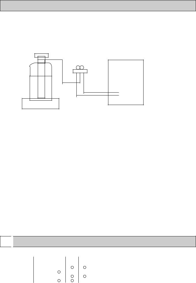
[3]Refrigerant recharging
(1)Refrigerant recharging process
1Direct enclosure from the bomb.
·Comfirm that R407C bomb on the market are syphon pipe. ·Leave the syphon pipe bomb raising and recharge it.
(By liquid refrigerant)
Unit
Gravimeter
(2) Recharge in refrigerant leakage case
·After recovering the all refrigerator in the unit, proceed to working. ·Do not release the refrigerant in the air.
·After complete the repair service, recharge the cycle with the specified amount of the liquid refrigerant.
3 
 COMBINATION OF INDOOR AND OUTDOOR UNITS
Indoor unit |
Outdoor unit |
|
|||
Service Ref. |
Service |
1.6 |
3 |
5 |
|
Manual No. |
VKAFT |
|
VKAFT YKAFT |
||
|
|
||||
PLH-GKH(S)BFT |
OC096 |
— |
|
|
|
PLH-KKHCFT |
OC123 |
|
|
— |
— |
PCH-GKH(S)AFT |
OC135 |
— |
|
|
|
PKH-FKHAFT |
OC130 |
|
|
|
— |
5

|
4 |
|
|
SPECIFICATIONS |
||||
|
|
|
|
|
|
|
||
|
4.1.Indoor unit |
|
|
|||||
|
|
Item |
|
|
Service Ref. |
|||
|
|
|
|
|||||
|
|
|
|
|
||||
|
|
Function |
|
|
|
|||
|
|
Capacity |
|
|
Btu/h |
|||
|
|
|
|
W |
||||
|
|
|
|
|
|
|
|
|
|
|
Total input |
|
|
kW |
|||
|
|
|
Service Ref. |
|
|
|||
|
|
|
Power supply(phase, cycle,voltage) |
|
||||
|
|
|
|
|
|
Input |
|
kW |
|
|
|
|
|
|
Running current |
|
A |
|
|
|
|
|
|
Starting current |
|
A |
|
|
|
External finish |
|
|
|||
|
|
|
Heat exchanger |
|
|
|||
|
|
|
|
|
|
Fan(drive) x No. |
|
|
|
|
UNIT |
|
|
|
Fan motor output |
|
kW |
|
|
|
|
|
Airflow(Low-High) |
|
K/min(CFM) |
|
|
|
|
|
|
|
|
||
|
|
INDOOR |
|
|
|
External static pressure |
mmAq,Pa |
|
|
|
Booster heater |
|
kW |
||||
|
|
|
|
|||||
|
|
|
Operation control & Thermostat |
|
||||
|
|
|
Noise level(Low-High) |
|
dB(A) |
|||
|
|
|
Cond. drain conn. O.D. |
|
mm,(in.) |
|||
|
|
|
|
|
|
|
W |
mm,(in.) |
|
|
|
Dimensions |
D |
mm,(in.) |
|||
|
|
|
|
|
|
|
H |
mm,(in.) |
|
|
|
Weight |
|
|
kg,(lbs) |
||
|
|
|
Service Ref. |
|
|
|||
|
|
|
Power supply (phase, cycle, voltage) |
|||||
|
|
|
|
|
|
Input |
|
kW |
|
|
|
|
|
|
Running current |
|
A |
|
|
|
|
|
|
Starting current |
|
A |
|
|
|
External finish |
|
|
|||
|
|
UNIT |
Refrigerant control |
|
|
|||
|
|
Compressor |
|
|
||||
|
|
|
|
|
||||
|
|
OUTDOOR |
|
|
|
Model |
|
|
|
|
Heat exchanger |
|
kW |
||||
|
|
|
|
|
|
Motor output |
|
|
|
|
|
|
|
|
Starter type |
|
|
|
|
|
|
|
|
Protection devices |
|
|
|
|
|
|
|
|
Fan(drive) x No. |
|
|
|
|
|
|
|
|
Fan motor output |
|
kW |
|
|
|
|
|
|
Airflow |
|
K/min(CFM) |
|
|
|
Defrost method |
|
|
|||
|
|
|
Noise level |
|
dB(A) |
|||
|
|
|
|
|
|
|
W |
mm,(in.) |
|
|
|
Dimensions |
D |
mm,(in.) |
|||
|
|
|
|
|
|
|
H |
mm,(in.) |
|
|
PIPING |
Weight |
|
|
kg,(lbs) |
||
|
|
Refrigerant |
|
|
||||
|
|
|
|
|
||||
|
|
|
|
|
|
Charge |
Liquid |
kg,(lbs) |
|
|
REFRIGERANT |
Pipe size O.D. |
mm,(in.) |
||||
|
|
outdoor unit |
Piping length |
|||||
|
|
|
|
|
|
|
Gas |
mm,(in.) |
|
|
|
Connection method |
Indoor side |
||||
|
|
|
|
|
|
|
Outdoor side |
|
|
|
|
Between the indoor & |
Height difference |
||||
|
|
|
|
|
|
|
|
|
PLH-1.6KKHCFT |
|
Cooling |
Heating |
15,000 |
15,900[20,600] |
4,400 |
4,650[6,050] |
1.59 |
1.51[3.20] |
PLH-1.6KKHCFT |
|
Single, 50Hz, 220-240V |
|
0.15 |
0.10[1.50] |
0.64 |
0.45[6.28] |
0.70 |
0.50[6.91] |
Galvanized sheets with gray heat insulation |
|
|
Plate fin coil |
Turbo fan [direct) x 1 |
|
|
0.030 |
13-16(460-565) |
|
|
0(direct blow) |
|
[1.4] |
Remote controller & built-in |
|
|
32-37 |
|
32(1-1/4) |
UNIT : 660(26) |
PANEL : 760(30) |
UNIT : 660(26) |
PANEL : 760(30) |
UNIT : 253(10) |
PANEL : 30(1-1/8) |
UNIT : 19(42)[20(44)] |
PANEL : 3.7(8)[3.7(8)] |
PUH-1.6VKAFT |
|
Single, 50Hz, 220-240V |
|
1.44 |
1.41 |
6.74 |
6.60 |
33 Munsell 5Y 7/1 Capillary tube
Hermetic
RH247VFC
1.2 Line start
Inner thermostat, High pressure switch Plate fin coil
Propeller (direct) x 1 0.065
45(1,590) Reverse cycle 49 870(34-1/4)
295+24 (11-5/8 and 1)
650 (25-5/8) 53(117) R407C 2.3(5.1) 9.52 (3/8) 15.88 (5/8) Flared Flared Max. 40m Max. 40m
6

Item |
|
|
Models |
|
Function |
|
|
||
Capacity |
|
Btu/h |
||
|
W |
|||
|
|
|
||
Total input |
|
kW |
||
|
Service Ref. |
|
|
|
|
Power supply(phase, cycle,voltage) |
|
||
|
Input |
|
kW |
|
|
Running current |
|
A |
|
|
Starting current |
|
A |
|
|
External finish |
|
|
|
UNIT |
Heat exchanger |
|
kW |
|
Fan motor output |
|
|||
INDOOR |
Fan(drive) x No. |
|
|
|
Booster heater |
|
kW |
||
|
Airflow(Low-High) |
|
K/ min (CFM) |
|
|
External static pressure |
Pa(mmAq) |
||
|
Operation control & Thermostat |
|
|
|
|
Noise level(Low-High) |
|
dB(A) |
|
|
Cond. drain conn. O.D. |
|
mm,(in) |
|
|
|
W |
mm,(in) |
|
|
Dimensions |
D |
mm,(in) |
|
|
|
H |
mm,(in) |
|
|
Weight |
|
kg,(lbs) |
|
|
Service Ref. |
|
|
|
|
Power supply (phase, cycle, voltage) |
|
||
|
Input |
|
kW |
|
|
Running current |
|
A |
|
|
Starting current |
|
A |
|
|
External finish |
|
|
|
|
Refrigerant control |
|
|
|
|
Compressor |
|
|
|
UNIT |
Model |
|
|
|
Motor output |
|
kW |
||
OUTDOOR |
Fan(drive) x No. |
|
|
|
|
Starter type |
|
|
|
|
Protection devices |
|
|
|
|
Heat exchanger |
|
|
|
|
Fan motor output |
|
kW |
|
|
Airflow |
|
K/ min (CFM) |
|
|
Defrost method |
|
|
|
|
Noise level |
|
dB(A) |
|
|
|
W |
mm,(in) |
|
|
|
|||
|
Dimensions |
D |
mm,(in) |
|
|
|
H |
mm,(in) |
|
|
Weight |
|
kg,(lbs) |
|
|
Refrigerant |
|
|
|
REFRIGERANT PIPING |
Charge |
|
kg,(lbs) |
|
|
||||
Pipe size O.D. |
Liquid |
mm,(in) |
||
|
||||
|
Gas |
mm,(in) |
||
|
|
|||
|
Connection method |
Indoor side |
|
|
|
Outdoor side |
|||
|
|
|||
|
Between the indoor & outdoor units |
Height difference |
||
|
|
Piping length |
||
w1 V…Internal Thermostat, HP switch
Y…Anti-phase protector, thermal relay, thermal switch, HP switch
|
PLH-3GKHBFT |
Cooling |
Heating |
26,300 |
28,700[35,800] |
7,700 |
8,400[10,500] |
3.57 |
3.59[5.69] |
|
PLH-3GKHBFT |
|
Single, 50Hz, 220-240V |
0.16 |
0.16[2.26] |
0.72 |
0.72[9.5] |
1.00 |
1.00[9.8] |
Galvanized sheets with gray heat insulation |
|
|
Plate fin coil |
|
Turbo fan (direct) x 1 |
|
0.050 |
|
14-18(495-640) |
|
0(direct blow) |
[2.1]
Remote controller & built-in
|
32-39 |
|
|
30(1-1/4) |
|
UNIT : 820(32-1/4) |
|
PANEL : 950(37-3/8) |
|
||
UNIT : 820(32-1/4) |
|
PANEL : 950(37-3/8) |
UNIT : 258(10-1/8) |
|
PANEL : 65(2-9/16) |
UNIT : 29(64) |
|
PANEL : 7(16) |
|
PUH-3VKAFT |
|
Single, 50Hz, 220-240V/3, 50Hz, 380-415V(4wires) |
||
3.41 |
|
|
|
3.43 |
|
4.96/15.58 |
|
5.04/5.61 |
58/37 |
|
58/37 |
Munsell 5Y 7/1 Capillary tube Hermetic NE-52VND 2.2/2.4
Line start w1
Plate fin coil Propeller (direct) x1 0.085
50(1764) Reverse cycle 52 870(34-1/4)
295+24 (11-5/8 add 1) 850(34-1/4)
75(165)
R407C
3.2(7.1) 9.52 (3/8) 15.88(5/8)
Flared
Flared
Max. 50m
Max. 50m
7

Item |
|
|
Models |
|
Function |
|
|
||
Capacity |
|
Btu/h |
||
|
W |
|||
|
|
|
||
Total input |
|
kW |
||
|
Service Ref. |
|
|
|
|
Power supply(phase, cycle,voltage) |
|
||
|
Input |
|
kW |
|
|
Running current |
|
A |
|
|
Starting current |
|
A |
|
|
External finish |
|
|
|
UNIT |
Heat exchanger |
|
kW |
|
Fan motor output |
|
|||
INDOOR |
Fan(drive) x No. |
|
|
|
Booster heater |
|
kW |
||
|
Airflow(Low-High) |
|
K/ min (CFM) |
|
|
External static pressure |
Pa(mmAq) |
||
|
Operation control & Thermostat |
|
|
|
|
Noise level(Low-High) |
|
dB(A) |
|
|
Cond. drain conn. O.D. |
|
mm,(in) |
|
|
|
W |
mm,(in) |
|
|
Dimensions |
D |
mm,(in) |
|
|
|
H |
mm,(in) |
|
|
Weight |
|
kg,(lbs) |
|
|
Service Ref. |
|
|
|
|
Power supply (phase, cycle, voltage) |
|
||
|
Input |
|
kW |
|
|
Running current |
|
A |
|
|
Starting current |
|
A |
|
|
External finish |
|
|
|
|
Refrigerant control |
|
|
|
|
Compressor |
|
|
|
UNIT |
Model |
|
|
|
Motor output |
|
kW |
||
OUTDOOR |
Fan(drive) x No. |
|
|
|
|
Starter type |
|
|
|
|
Protection devices |
|
|
|
|
Heat exchanger |
|
|
|
|
Fan motor output |
|
kW |
|
|
Airflow |
|
K/ min (CFM) |
|
|
Defrost method |
|
|
|
|
Noise level |
|
dB(A) |
|
|
|
W |
mm,(in) |
|
|
|
|||
|
Dimensions |
D |
mm,(in) |
|
|
|
H |
mm,(in) |
|
|
Weight |
|
kg,(lbs) |
|
|
Refrigerant |
|
|
|
REFRIGERANT PIPING |
Charge |
|
kg,(lbs) |
|
|
||||
Pipe size O.D. |
Liquid |
mm,(in) |
||
|
||||
|
Gas |
mm,(in) |
||
|
|
|||
|
Connection method |
Indoor side |
|
|
|
Outdoor side |
|||
|
|
|||
|
Between the indoor & outdoor units |
Height difference |
||
|
|
Piping length |
||
|
PLH-5GKHSBFT |
Cooling |
Heating |
41,300 |
45,700[56,000] |
12,100 |
13,400[16,400] |
4.55 |
4.77[7.77] |
|
PLH-5GKHSBFT |
|
Single, 50Hz, 220-240V |
0.28 |
0.28[3.28] |
1.27 |
1.27[13.8] |
1.50 |
1.50[14.0] |
Galvanized sheets with gray heat insulation |
|
|
Plate fin coil |
|
Turbo fan (direct) x 2 |
|
0.050+0.050 |
|
24-33(850-1165) |
|
0(direct blow) |
[3.0]
Remote controller & built-in
|
36-43 |
|
|
30(1-1/4) |
|
UNIT : 1340(52-3/4) |
|
PANEL : 1470(57-7/8) |
|
||
UNIT : 820(32-1/4) |
|
PANEL : 950(37-3/8) |
UNIT : 258(10-1/8) |
|
PANEL : 65(2-9/16) |
UNIT : 45(99) |
|
PANEL :10(22) |
|
PUH-5YKSAFT |
|
3, 50Hz, 380-415V(4wire) |
||
4.27 |
|
|
|
4.49 |
|
6.90 |
|
7.34 |
53 |
|
53 |
Munsell 5Y 7/1 Capillary tube Hermetic ZR61KCE-TFD 3.5
Line start
Internal thermostat, Anti-phasa protector, Thermal switch, HP switch Plate fin coil
Propeller (direct) x2 0.085+0.085 95(3550) Reverse cycle
55 970(38-3/16) 345+24(13-9/16 add 1) 1258(49-1/2) 114(251)
R407C
5.4(11.9)
9.52(3/8)
19.05(3/4) Flared Flared Max. 50m Max. 50m
8

Rating Conditions (JIS B8616)
Item |
|
|
|
|
|
Service Ref. |
|
PCH-3GKHAFT |
|
|
PCH-4GKHSA1 |
||||||
|
|
|
|
|
|
|
|
|
|
|
|
|
|
|
|||
Function |
|
|
|
|
|
Cooling |
|
|
Heating |
Cooling |
|
|
Heating |
||||
Capacity |
|
|
|
Btu/h |
25,600 |
|
29,000 (36,200) |
34,100 |
|
35,700 (44,900) |
|||||||
|
|
|
W |
7,500 |
|
|
8,500 (10,600) |
10,000 |
|
|
10,450 (13,150) |
||||||
|
|
|
|
|
|
|
|
||||||||||
Total input |
|
|
|
kW |
3.28 |
|
3.07 (5.17) |
3.36 |
|
3.35(6.05) |
|||||||
|
Service Ref. |
|
|
|
|
|
PCH-3GKHAFT |
|
|
PCH-4GKHSA1 |
|||||||
|
Power supply |
|
|
|
|
|
|
|
|
Single phase. 50Hz. 220-240V |
|
|
|
||||
|
|
Input |
|
|
|
kW |
0.13 |
|
0.13 (2.23) |
0.16 |
|
0.16 (2.86) |
|||||
|
|
Running current |
A |
0.55 |
|
0.55 (9.30) |
0.70 |
|
0.70 (11.95) |
||||||||
|
|
Starting current |
A |
1.27 |
|
1.27 (10.02) |
1.48 |
|
1.48 (12.73) |
||||||||
|
External finish |
|
|
|
|
|
|
|
|
Munsell 0.70Y 8.59 / 0.97 |
|
|
|
||||
|
Heat exchanger |
|
|
|
|
|
|
|
|
|
|
Plate fin coil |
|
|
|
||
UNIT |
|
Fan(drive))No. |
|
|
|
|
|
Sirocco (direct) 3 |
|
|
|
||||||
|
Fan motor output |
kW |
|
|
0.07 |
|
|
|
0.09 |
||||||||
INDOOR |
|
|
|
|
|
|
|
|
|
|
|
|
|
|
|
||
Booster heater |
|
|
|
kW |
|
|
(2.1) |
|
|
|
(2.7) |
||||||
|
|
Airflow(Low-High) |
K/min <CFM> |
14 -18 <494-635> |
|
|
20 -25 <706-883> |
||||||||||
|
|
External static pressure |
Pa(mmAq) |
|
|
|
|
|
0 (direct blow) |
|
|
|
|||||
|
|
|
|
|
|
|
|
|
|
|
|
|
|
||||
|
Operation control & Thermostat |
|
|
|
|
|
Remote controller & built-in |
|
|
|
|||||||
|
Noise level(Low-High) |
|
|
|
dB(A) |
|
|
37 - 43 |
|
|
|
40 - 45 |
|||||
|
Cond. drain connection O.D. |
mm,(in) |
|
|
|
|
|
26 (1) |
|
|
|
||||||
|
|
|
|
|
W |
mm,(in) |
|
|
|
|
|
1,310 ( 51-9/16 ) |
|
|
|
||
|
Dimensions |
|
|
D |
mm,(in) |
|
|
|
|
|
680 (26-3/4) |
|
|
|
|||
|
|
|
|
|
H |
mm,(in) |
210 (8-1/4) |
|
|
270 (10-5/8) |
|||||||
|
Weight |
|
|
|
kg,(lbs) |
|
|
36 (79) |
|
|
39.5 (87) |
||||||
|
Service Ref. |
|
|
|
|
|
PUH-3VKAFT |
|
|
PUH-4YKSA3 |
|||||||
|
Power supply |
|
|
|
|
|
|
|
|
VKA...1phase, 50Hz, 220-240V |
|
|
|
||||
|
|
Input |
|
|
|
kW |
3.15 |
|
2.94 |
|
|
3.20 |
|
3.19 |
|||
|
|
Running current |
A |
13.82 / 5.16 |
|
12.89 / 4.81 |
5.24 |
|
5.22 |
||||||||
|
|
Starting current |
A |
58 / 37 |
|
58 / 37 |
|
40 |
|
40 |
|||||||
|
External finish |
|
|
|
|
|
|
|
|
|
Munsell 5Y 7/1 |
|
|
|
|||
|
Refrigerant control |
|
|
|
|
|
|
|
|
|
Capillary tube |
|
|
|
|||
|
Compressor |
|
|
|
|
|
|
|
|
|
|
Hermetic |
|
|
|
||
UNIT |
|
Model |
|
|
|
|
|
NH52YDA |
|
|
NH56YDA |
||||||
|
Motor output |
kW |
|
|
2.2 / 2.4 |
|
|
|
2.7 |
||||||||
|
|
|
|
|
|
|
|||||||||||
OUTDOOR |
|
Starter type |
|
|
|
|
|
|
|
Line start |
|
|
|
||||
|
Protection devices |
|
VKA...Inner thermostat. High-pressure switch YKA...Anti-phase protector, Thermal relay, Thermal switch, High-pressute switch |
||||||||||||||
|
|
|
|||||||||||||||
|
Heat exchanger |
|
|
|
|
|
|
|
|
|
|
Plate fin coil |
|
|
|
||
|
|
Fan(drive))No. |
|
|
Propeller (direct) 1 |
|
|
Propeller (direct) 2 |
|||||||||
|
|
Fan motor output |
kW |
|
|
0.085 |
|
|
0.065 + 0.065 |
||||||||
|
|
Airflow |
|
|
|
K/min <CFM> |
50 (1,764) |
|
|
95 (3,350) |
|||||||
|
Defrost method |
|
|
|
|
|
|
|
|
|
Reverse cycle |
|
|
|
|||
|
Crankcase heater |
|
|
|
W |
|
|
38 |
|
|
|
38 |
|||||
|
Noise level |
|
|
|
dB(A) |
|
|
52 |
|
|
|
54 |
|||||
|
|
|
|
|
W |
mm,(in) |
|
|
|
|
|
870 <34-1/4> |
|
|
|
||
|
Dimensions |
|
|
D |
mm,(in) |
|
|
|
|
295 + 24 <11-5/8 add 1> |
|
|
|
||||
|
|
|
|
|
H |
mm,(in) |
850 (33-7/16) |
|
|
1,258 (49-1/2) |
|||||||
|
Weight |
|
|
|
kg,(lbs) |
|
|
75 (165) |
|
|
94 (207) |
||||||
|
Refrigerant |
|
|
|
|
|
|
|
|
|
|
R407C |
|
|
|
||
REFRIGERANT PIPING |
|
Charge |
|
|
|
kg,(lbs) |
|
|
3.2 (7.1) |
|
|
4.2 (9.2) |
|||||
Pipe size O.D. |
|
Liquid |
mm,(in) |
9.52 (3/8) |
|
|
9.52 (3/8) |
||||||||||
|
|
|
|
||||||||||||||
|
|
Gas |
mm,(in) |
15.88 (5/8) |
|
|
19.05 (3/4) |
||||||||||
|
|
|
|
|
|
||||||||||||
|
Connection method |
|
|
Indoor side |
|
|
|
|
|
|
Flared |
|
|
|
|||
|
|
|
|
|
|
|
|
|
|
|
|
|
|
|
|
||
|
|
|
Outdoor side |
|
|
|
|
|
|
Flared |
|
|
|
||||
|
|
|
|
|
|
|
|
|
|
|
|
|
|
||||
|
Between the indoor & outdoor unit |
Height difference |
|
|
|
|
|
|
Max. 50m |
|
|
|
|||||
|
Piping length |
|
|
|
|
|
|
Max. 50m |
|
|
|
||||||
|
|
|
|
|
|
|
|
|
|
|
|
|
|
||||
Notes1. Rating Conditions (JIS B8616) |
|
|
2. Guaranteed operating range |
|
|
|
|
||||||||||
|
Cooling : Indoor |
: 27:(80oF)DB. 19:(66oF)WB |
|
|
|
|
|
|
|
|
|
|
|
||||
|
|
|
|
|
|
|
|
Indoor |
|
|
Outdoor |
||||||
|
|
Outdoor : 35:(95oF)DB. 24:(75oF)WB |
|
|
|
|
|
|
|
|
|
||||||
|
|
|
|
|
|
Upper limit |
|
35: DB, 22.5: WB |
|
|
46: DB |
||||||
|
Heating : Indoor |
: 20:(68oF) |
|
|
Cooling |
|
|
|
|
|
|||||||
|
|
|
|
|
Lower limit |
|
21: DB, 15.5: WB |
|
|
-5: DB |
|||||||
|
|
|
o |
o |
|
|
|
|
|
|
|
||||||
|
|
Outdoor : 7:(45 F)DB. 6:(43 F)WB. |
|
|
|
|
|
|
|
|
|
|
|
||||
|
Refrigerant piping length (one way) : 5m(16ft) |
|
Heating |
|
|
Upper limit |
|
|
27: DB |
|
21: DB, 15.5: WB |
||||||
|
3. Above data based on indicated voltage |
|
|
|
|
Lower limit |
|
|
20: DB |
|
-8.5: DB, -9.5: WB |
||||||
|
|
|
|
|
|
|
|
|
|||||||||
|
|
|
|
|
|
|
|
|
|
|
|
|
|||||
|
Indoor Unit |
1 phase 240V 50Hz |
|
|
|
|
|
|
|
|
|
|
|
|
|||
|
Outdoor Unit |
1 phase 240V 50Hz / 3 phase 415V 50Hz |
|
|
|
|
|
|
|
|
|
||||||
9

Rating Conditions (JIS B8616)
Item |
|
|
|
|
Service Ref. |
|
Function |
|
|
|
|
||
Capacity |
|
|
|
Btu/h |
||
|
|
|
W |
|||
|
|
|
|
|
||
Total input |
|
|
|
kW |
||
|
Service Ref. |
|
|
|
|
|
|
Power supply |
|
|
|
|
|
|
Input |
|
|
|
kW |
|
|
Running current |
A |
||||
|
Starting current |
A |
||||
|
External finish |
|
|
|
|
|
UNIT |
Heat exchanger |
|
|
|
kW |
|
Fan motor output |
||||||
INDOOR |
Fan(drive))No. |
|
||||
Booster heater |
|
|
|
kW |
||
|
Airflow(Low-High) |
K/min <CFM> |
||||
|
External static pressure |
Pa(mmAq) |
||||
|
Operation control & Thermostat |
|
||||
|
Noise level(Low-High) |
|
|
|
dB(A) |
|
|
Cond. drain connection O.D. |
mm,(in) |
||||
|
|
|
|
W |
mm,(in) |
|
|
Dimensions |
|
|
D |
mm,(in) |
|
|
|
|
|
H |
mm,(in) |
|
|
Weight |
|
|
|
kg,(lbs) |
|
|
Service Ref. |
|
|
|
|
|
|
Power supply |
|
|
|
|
|
|
Input |
|
|
|
kW |
|
|
Running current |
A |
||||
|
Starting current |
A |
||||
|
External finish |
|
|
|
|
|
|
Refrigerant control |
|
|
|
|
|
|
Compressor |
|
|
|
|
|
UNIT |
Model |
|
|
|
|
|
Motor output |
kW |
|||||
|
||||||
OUTDOOR |
Starter type |
|
||||
Protection devices |
|
|||||
|
|
|||||
|
Heat exchanger |
|
|
|
|
|
|
Fan(drive))No. |
|
||||
|
Fan motor output |
kW |
||||
|
Airflow |
|
|
|
K/min <CFM> |
|
|
Defrost method |
|
|
|
|
|
|
Crankcase heater |
|
|
|
W |
|
|
|
|
|
|||
|
Noise level |
|
|
|
dB(A) |
|
|
|
|
|
W |
mm,(in) |
|
|
Dimensions |
|
|
D |
mm,(in) |
|
|
|
|
|
H |
mm,(in) |
|
|
Weight |
|
|
|
kg,(lbs) |
|
|
Refrigerant |
|
|
|
|
|
REFRIGERANT PIPING |
Charge |
|
|
|
kg,(lbs) |
|
Pipe size O.D. |
|
Liquid |
mm,(in) |
|||
|
|
|||||
|
|
Gas |
mm,(in) |
|||
|
|
|
||||
|
Connection method |
|
|
Indoor side |
||
|
|
|
Outdoor side |
|||
|
|
|
|
|||
|
Between the indoor & outdoor unit |
Height difference |
||||
|
Piping length |
|||||
|
|
|
|
|||
Notes1. Rating Conditions (JIS B8616) |
|
|||||
|
Cooling : Indoor |
: 27:(80oF)DB. 19:(66oF)WB |
||||
|
Outdoor : 35:(95oF)DB. 24:(75oF)WB |
|||||
Heating : Indoor : 20:(68oF)DB.
Outdoor : 7:(45oF)DB. 6:(43oF)WB. Refrigerant piping length (one way) : 5m(16ft)
3. Above data based on indicated voltage Indoor Unit 1 phase 240V 50Hz Outdoor Unit 3 phase 415V 50Hz
PCH-5GKHSAFT |
|
PCH-6GKHSA1 |
||||
Cooling |
|
Heating |
|
Cooling |
|
Heating |
|
|
|
||||
42,300 |
|
47,400 (57,700) |
|
49,500 |
|
51,200 (61,400) |
12,400 |
|
13,900 (16,900) |
|
14,500 |
|
15,000 (18,000) |
4.45 |
|
4.40 (7.40) |
|
4.97 |
|
4.82 (7.82) |
PCH-5GKHSAFT |
|
PCH-6GKHSA1 |
||||
|
|
Single phase. 50Hz. 220-240V |
|
|
||
0.24 |
|
0.24 (3.24) |
|
0.24 |
|
0.24 (3.24) |
1.06 |
|
1.06 (13.56) |
|
1.06 |
|
1.06 (13.56) |
2.20 |
|
2.20 (14.70) |
|
2.20 |
|
2.20 (14.70) |
|
|
Munsell 0.70Y 8.59 / 0.97 |
|
|
||
|
|
Plate fin coil |
|
|
|
|
|
|
Sirocco (direct) 4 |
|
|
||
|
0.15 |
|
|
|
||
|
27 -34 <953-1,200> |
|
|
|||
|
|
0 (direct blow) |
|
|
||
|
(3.0) |
|
|
|
||
|
|
Remote controller & built-in |
|
|
||
|
41-46 |
|
|
42-48 |
||
|
26 (1) |
|
|
|
||
|
1,620 (63-3/4) |
|
|
|||
|
680 (26-3/4) |
|
|
|
||
|
270 (10-5/8) |
|
|
|
||
|
46 (101) |
|
|
48 (106) |
||
PUH-5YSAFT |
|
PUH-6YKSA2 |
||||
|
|
3 phases. 50Hz. 380-415V (4 wires) |
||||
4.21 |
|
4.16 |
|
4.73 |
|
4.58 |
6.89 |
|
6.81 |
|
7.74 |
|
7.50 |
53 |
|
53 |
|
74 |
|
74 |
|
|
Munsell 5Y 7/1 |
|
|
||
|
|
Capillary tube |
|
|
||
|
|
Hermetic |
|
|
|
|
ZR61KC-ETED |
|
ZR68KC-TFD |
||||
|
3.5 |
|
|
4.0 |
||
|
|
|
|
|
|
|
Line start
Anti-phase protector, Internal thermostat, Thermal switch, High-pressure switch
Plate fin coil
Propeller (direct) 2
0.085 + 0.085 |
|
0.10 + 0.10 |
||||
95 (3,350) |
|
100 (3,530) |
||||
|
|
|
Reverse cycle |
|
||
|
|
|
38 |
|
||
|
55 |
|
|
|
56 |
|
|
|
|
970 (38-3/16) |
|
||
|
|
345 + 24 (13-9/16 add 1) |
|
|||
|
|
|
1,258 (49-1/2) |
|
||
|
114 (251) |
|
117 (258) |
|||
|
|
|
|
R407C |
|
|
|
5.4 (11.9) |
|
5.0 (11.0) |
|||
|
|
|
9.52 (3/8) |
|
||
|
|
|
19.05 (3/4) |
|
||
|
|
|
|
Flared |
|
|
|
|
|
|
Flared |
|
|
|
|
|
|
Max. 50m |
|
|
|
|
|
|
Max. 50m |
|
|
2. Guaranteed operating range |
|
|||||
|
|
|
|
|
|
|
|
|
|
|
|
Indoor |
Outdoor |
Cooling |
|
Upper limit |
|
35: DB, 22.5: WB |
46: DB |
|
|
Lower limit |
|
21: DB, 15.5: WB |
-5: DB |
||
|
|
|
||||
Heating |
|
Upper limit |
|
|
27: DB |
21: DB, 15.5: WB |
|
Lower limit |
|
|
20: DB |
-8.5: DB, -9.5: WB |
|
|
|
|
|
|||
10
|
|
|
|
|
|
|
|
|
|
|
|
|
|
|
|
|
|
|
|
|
|
|
|
|
Item |
|
|
|
|
|
Service Ref. |
|
PKH-1.6FKHAFT |
|
|
|
|
|
|
|
|
|
|
|
|||
|
|
|
|
|
|
|
|
|
|
|
|
|
|
|
|
|
|
|
|
|
|
|
|
|
Function |
|
|
|
|
|
Cooling |
|
Heating |
|
|
|
Capacity |
|
|
|
|
W |
4,500 |
|
4,650(6,050) |
|
|
|
|
|
|
|
Btu/h |
15,350 |
|
15,900(20,600) |
|
||
|
|
|
|
|
|
|
|
|
|||
|
Total input |
|
|
|
|
kW |
1.51 |
|
1.48(2.88) |
|
|
|
|
Service Ref. |
|
|
|
|
|
PKH-1.6FKHAFT |
|
||
|
|
Power supply(phase,cycle,voltage) |
|
|
Single, 50Hz, 220-240V |
|
|||||
|
|
|
Input |
|
|
|
kW |
0.07 |
|
0.07(1.47) |
|
|
|
|
Running current |
|
|
A |
0.32 |
|
0.32(6.15) |
|
|
|
|
|
Starting current |
|
|
A |
0.40 |
|
0.40(6.23) |
|
|
|
|
External finish |
|
|
|
|
Munsell 3.4Y 7.7/0.8(White) |
|
|||
|
UNIT |
Heat exchanger |
|
|
|
|
|
Plate fin coil |
|
||
|
|
Fan(drive) |
No. |
|
|
|
|
Line flow(direct) 1 |
|
||
|
|
|
|
|
|
|
|
||||
|
INDOOR |
|
Fan motor output |
|
|
kW |
|
0.030 |
|
||
|
|
Airflow(Low-High) |
|
|
m3/X<CFM> |
|
10-13<353-459> |
|
|||
|
|
|
|
|
|
|
|||||
|
|
|
External static pressure |
|
Pa(mmAq) |
|
0<direct blow> |
|
|||
|
|
Booster heater |
|
|
|
kW |
|
1.4 |
|
||
|
|
Operation control & Thermostat |
|
Remote controller & built-in |
|
||||||
|
|
Noise level(Low-High) |
|
|
>(A) |
|
36-43 |
|
|||
|
|
Cond. drain connection. O.D. |
|
|
A,<in.> |
|
20<13/16> |
|
|||
|
|
Dimensions |
|
W |
|
A,<in.> |
|
1,250<49-3/16> |
|
||
|
|
|
D |
|
A,<in.> |
|
200<7-7/8> |
|
|||
|
|
|
|
|
H |
|
A,<in.> |
|
300<11-13/16> |
|
|
|
|
Weight |
|
|
|
|
kg,<lbs> |
|
18<40> |
|
|
|
|
Service Ref. |
|
|
|
|
|
PUH-1.6VKAFT |
|
||
|
|
Power supply (phase, cycle, voltage) |
|
|
Single, 50Hz, 220-240V |
|
|||||
|
|
|
Input |
|
|
|
kW |
1.44 |
1.41 |
|
|
|
|
|
Running current |
|
|
A |
6.74 |
6.60 |
|
||
|
|
|
Staring current |
|
|
A |
|
33 |
|
||
|
|
External finish |
|
|
|
|
|
Munsell 5y 7/1 |
|
||
|
|
Refrigerant control |
|
|
|
|
|
Capillary tube |
|
||
|
UNIT |
Compressor |
|
|
|
|
|
Hermetic |
|
||
|
|
Motor output |
|
|
kW |
|
1.2 |
|
|||
|
|
|
Model |
|
|
|
|
|
RE247VFC |
|
|
|
OUTDOOR |
|
|
|
|
|
|
|
|
|
|
|
|
Starter type |
|
|
|
|
Line start |
|
|||
|
|
|
|
|
|
|
|
||||
|
|
|
Protection devices |
|
|
|
Internal thermostat, HP switch |
|
|||
|
|
Heat exchanger |
|
|
|
|
|
Plate fin coil |
|
||
|
|
|
Fan(drive) No. |
|
|
|
|
Propeller (direct) 1 |
|
||
|
|
|
Fan motor output |
|
|
kW |
|
0.065 |
|
||
|
|
|
Airflow |
|
|
|
m3/X,<CFM> |
|
45<1,590> |
|
|
|
|
Defrost method |
|
|
|
|
|
Reverse cycle |
|
||
|
|
Noise level |
|
|
|
>(A) |
|
49 |
|
||
|
|
Dimensions |
|
W |
A,<in.> |
|
870<34-1/4> |
|
|||
|
|
|
D |
A,<in.> |
|
295+24<11-5/8 add 1> |
|
||||
|
|
|
|
|
H |
A,<in.> |
|
650<25-5/8> |
|
||
|
|
Weight |
|
|
|
|
kg,<lbs> |
|
53<117> |
|
|
|
PIPING |
Refrigerant |
|
|
|
|
|
R-407C |
|
||
|
|
Charge |
|
|
|
kg,<lbs> |
|
2.3<5.1> |
|
||
|
|
|
|
|
|
|
|
||||
|
REFRIGERANT |
Pipe size O.D. |
|
Liquid |
A,<in.> |
|
9.52<3/8> |
|
|||
|
|
Piping length |
|
Max. 40m |
|
||||||
|
|
|
|
|
Gas |
A,<in.> |
|
15.88<5/8> |
|
||
|
|
Connection method |
|
Indoor side |
|
|
Flared |
|
|||
|
|
|
Outdoor side |
|
Flared |
|
|||||
|
|
|
|
|
|
|
|||||
|
|
Between the indoor & outdoor unit |
Height difference |
|
Max. 40m |
|
|||||
|
|
|
|
|
|
|
|
|
|||
|
|
|
|
|
|
|
|
|
|
|
|
Note. Rating Conditions (JIS B 8616) |
|
|
|
|
|
|
|
||||
|
Cooling : Indoor |
: 27°C (80°C) DB, 19°C (66°F) WB |
|
|
|
|
|
||||
|
|
Outdoor : 35°C (95°F) DB, 24°C (75°F) WB |
|
|
|
|
|
||||
|
Heating : Indoor |
: 20°C (68°F) |
|
|
|
|
|
|
|
|
|
|
|
Outdoor : 7°C (45°F) DB, 6°C (43°F) WB |
|
|
|
|
|
||||
11

|
|
|
|
|
|
|
|
|
|
|
|
|
|
|
|
|
|
|
|
Item |
|
|
|
|
|
Service Ref. |
|
PKH-3FKHAFT |
|
|
|
|
|
|
|
|
|||
|
|
|
|
|
|
|
|
|
|
|
|
|
|
|
|
|
|
|
|
Function |
|
|
|
|
|
Cooling |
|
Heating |
|
Capacity |
|
|
|
|
W |
7,900 |
|
9,100(11,200) |
|
|
|
|
|
Btu/h |
27,000 |
|
31,000(38,200) |
||
|
|
|
|
|
|
|
|||
Total input |
|
|
|
|
kW |
3.25 |
|
3.04(5.14) |
|
|
Service Ref. |
|
|
|
|
|
PKH-3FKHAFT |
||
|
Power supply(phase,cycle,voltage) |
|
Single, 50Hz, 220-240V |
||||||
|
|
Input |
|
|
|
kW |
0.095 |
|
0.095(2.195) |
|
|
Running current |
|
|
A |
0.44 |
|
0.44(9.19) |
|
|
|
Starting current |
|
|
A |
0.80 |
|
0.80(9.55) |
|
|
External finish |
|
|
|
|
Munsell 3.4Y 7.7/0.8(White) |
|||
UNIT |
Heat exchanger |
|
|
|
|
|
Plate fin coil |
||
|
Fan(drive) |
No. |
|
|
|
|
Line flow(direct) 2 |
||
|
|
|
|
|
|
||||
INDOOR |
|
Fan motor output |
|
|
kW |
|
0.040 |
||
|
Airflow(Low-High) |
|
|
m3/X<CFM> |
|
15-20<530-706> |
|||
|
|
|
|
|
|||||
|
|
External static pressure |
|
Pa(mmAq) |
|
0(direct blow) |
|||
|
Booster heater |
|
|
|
kW |
|
2.1 |
||
|
Operation control & Thermostat |
|
Remote controller & built-in |
||||||
|
Noise level(Low-High) |
|
|
>(A) |
|
35-43 |
|||
|
Cond. drain conn. O.D. |
|
|
A,<in.> |
|
20<13/16> |
|||
|
Dimensions |
|
W |
|
A,<in.> |
|
1,400<55-1/8> |
||
|
|
D |
|
A,<in.> |
|
235<9-1/4> |
|||
|
|
|
|
H |
|
A,<in.> |
|
340<13-3/8> |
|
|
Weight |
|
|
|
|
kg,<lbs> |
|
26<57> |
|
|
Service Ref. |
|
|
|
|
|
PUH-3VKAFT |
||
|
Power supply (phase, cycle, voltage) |
|
Single, 50Hz, 220-240V/3 |
||||||
|
|
Input |
|
|
|
kW |
3.15/3.15 |
2.94/2.94 |
|
|
|
Running current |
|
|
A |
13.82/5.16 |
12.89/4.81 |
||
|
|
Staring current |
|
|
A |
|
58/37 |
||
|
External finish |
|
|
|
|
|
Munsell 5Y 7/1 |
||
|
Refrigerant control |
|
|
|
|
|
Capillary tube |
||
UNIT |
Compressor |
|
|
|
|
|
Hermetic |
||
|
Motor output |
|
|
kW |
|
2.2 |
|||
|
|
Model |
|
|
|
|
|
NE52VND |
|
OUTDOOR |
|
|
|
|
|
|
|
|
|
|
Starter type |
|
|
|
|
Line start |
|||
|
|
|
|
|
|
||||
|
|
Protection devices |
|
|
|
Internal thermostat, HP switch/Thermal relay, thermal switch |
|||
|
Heat exchanger |
|
|
|
|
|
Plate fin coil |
||
|
|
Fan(drive) No. |
|
|
|
|
Propeller (direct) 1 |
||
|
|
Fan motor output |
|
|
kW |
|
0.085 |
||
|
|
Airflow |
|
|
|
m3/X<CFM> |
|
50<1,764> |
|
|
Defrost method |
|
|
|
|
|
Reverse cycle |
||
|
Noise level |
|
|
|
>(A) |
|
52 |
||
|
Dimensions |
|
W |
A,<in.> |
|
870(34-1/4) |
|||
|
|
D |
A,<in.> |
295+24<11-5/8 add 1> |
|||||
|
|
|
|
H |
A,<in.> |
|
850<33-7/16> |
||
|
Weight |
|
|
|
|
kg,<lbs> |
|
75<165> |
|
PIPING |
Refrigerant |
|
|
|
|
|
R-407C |
||
|
Charge |
|
|
|
kg,<lbs> |
|
3.2<7.1> |
||
|
|
|
|
|
|
||||
REFRIGERANT |
Pipe size O.D. |
|
Liquid |
A,<in.> |
|
9.52<3/8> |
|||
|
Piping lenghth |
|
Max. 50m |
||||||
|
|
|
|
Gas |
A,<in.> |
|
15.88<5/8> |
||
|
Connection method |
|
Indoor side |
|
|
Flared |
|||
|
|
Outdoor side |
|
Flared |
|||||
|
|
|
|
|
|||||
|
Between the indoor & outdoor unit |
Height difference |
|
Max. 50m |
|||||
|
|
|
|
|
|
|
|||
|
|
|
|
|
|
|
|
|
|
Note. Rating Conditions (JIS B 8616) |
|
|
|
|
|
|
|||
Cooling : Indoor |
: 27°C (80°C) DB, 19°C (66°F) WB |
|
|
|
|
||||
|
Outdoor : 35°C (95°F) DB, 24°C (75°F) WB |
|
|
|
|
||||
Heating : Indoor |
: 20°C (68°F) |
|
|
|
|
|
|
|
|
|
Outdoor : 7°C (45°F) DB, 6°C (43°F) WB |
|
|
|
|
||||
12
4.2.Outdoor unit
1. REFILLING REFRIGERANT CHARGE (R-22 : kg)
Service Ref. |
|
|
|
Refrigerant piping length (one way) |
|
|
|
||||
|
|
|
|
|
|
|
|
|
|
||
5m |
10m |
15m |
20m |
25m |
30m |
35m |
40m |
45m |
50m |
||
|
|||||||||||
|
|
|
|
|
|
|
|
|
|
|
|
PUH-1.6VKAFT |
1.6 |
1.8 |
1.9 |
2.0 |
2.2 |
2.3 |
2.4 |
2.5 |
— |
— |
|
|
|
|
|
|
|
|
|
|
|
|
|
PUH-3VKAFT |
2.5 |
2.7 |
2.8 |
2.9 |
3.1 |
3.2 |
3.3 |
3.4 |
3.6 |
3.7 |
|
|
|
|
|
|
|
|
|
|
|
|
|
PUH-5YKSAFT |
4.7 |
4.8 |
5.0 |
5.1 |
5.3 |
5.4 |
5.6 |
5.7 |
5.9 |
6.0 |
|
|
|
|
|
|
|
|
|
|
|
|
|
2. COMPRESSOR TECHNICAL DATA at 20˚C
Compressor Model RE247VFC NE52VND
U-V
Winding (R-C)
U-W Resistance (S-C)
(!)
W-V
at 25˚C
Compressor Model |
ZR61KCETED |
T1-T2
Winding Resistance T2-T3
(!)
T3-T1
13
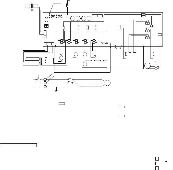
5 |
|
|
WIRING DIAGRAM |
|
|
|
|
PUH-1.6VKAFT |
|
|
|
|
|||
SYMBOL |
NAME |
SYMBOL |
NAME |
SYMBOL |
NAME |
||
MC |
COMPRESSOR |
TB1,3 |
TERMINAL BLOCK |
X12<O.B> |
COMPRESSOR RELAY |
||
MF |
OUTDOOR FAN MOTOR (INNER THERMOSTAT) |
63H1 |
CONTROL HIGH PRESSURE SWITCH |
X13<O.B> |
SOLENOID COIL RELAY |
||
C1 |
FAN MOTOR CAPACITOR |
63H2 |
PROTECT HIGH PRESSURE SWITCH |
X14<O.B> |
SOLENOID COIL RELEY |
||
C2 |
COMPRESOR CAPACITOR |
O.B |
OUTDOOR CONTROLLER BOARD |
X16 |
HIGH PRESSURE RELAY |
||
RT |
PIPE TEMP. THERMISTOR |
ZNR<O.B> |
SURGE ABSORBER |
SW1,2,3<O.B> |
CHECK,SERVICE SELECT SWITCH |
||
HC |
CRANKCASE HEATER |
F<O.B> |
FUSE(6.3A) |
LD1-LD8<O.B> |
CHECK,SERVICE LED |
||
52C |
CONTACTOR |
FC<O.B> |
FAN CONTROLLER |
|
|
||
21S4 |
4-WAY VALVE SOLENOID COIL |
X11<O.B> |
CRANKCASE HEATER RELAY |
|
|
||
21R |
BYPASS VALVE SOLENOID COIL |
T |
TRANSFORMER |
|
|
||
TO INDOOR UNIT |
1 |
YLW |
|
|
|
|
LED |
|
|
|
|
|
|
|
|
|
|
|
|
|
|
|
|
|
|
|
RT |
|
|
|
|
|
|
|
|
|
|
|
|||
2 |
ORN |
|
|
|
|
|
|
|
|
|
|
|
|
|
|
|
|
|
||
CONNECTING WIRES |
|
|
|
|
|
|
|
|
|
|
|
|
|
|
|
|
|
|||
|
|
|
|
|
|
|
|
|
|
|
|
|
|
|
|
|
|
|||
3 |
BRN |
|
|
|
|
|
|
|
|
|
|
|
|
|
|
|
|
|
|
|
DC 12V (polar) |
O.B |
|
|
|
|
|
|
|
|
|
|
|
|
|
|
|
|
|||
TB3 |
|
|
|
|
|
|
|
|
|
|
|
|
|
|
|
|
||||
|
|
|
|
|
|
|
|
|
|
|
|
|
|
|
|
|
||||
|
|
|
|
|
|
|
|
|
|
|
|
|
|
|
|
|
|
|
||
|
|
|
SW1 |
LD1 LD2 LD3 LD4 LD5 LD6 LD7 LD8 |
|
|
|
|
|
|
|
4 3 2 1 |
|
|
||||||
|
|
|
SW2 |
CN2 |
X14 X13 |
X12 X11 |
|
CN4 |
|
|
|
|||||||||
|
|
|
|
|
|
|
|
|
|
|
||||||||||
|
|
|
|
|
|
|
|
|
|
|
|
|
|
|
|
|
||||
|
|
|
SW3 |
OFF |
|
|
|
|
|
|
|
|
|
|
|
|
|
|
||
|
|
|
|
|
|
|
|
|
|
|
|
|
|
|
|
|
|
63H1 |
||
|
|
|
2 1 |
ON |
|
|
X14 |
X13 |
X12 |
|
X11 |
|
||||||||
|
|
|
|
|
|
|
|
|
|
|
|
|
|
|
|
|
|
|
||
|
|
|
3 |
|
|
|
|
|
|
|
|
|
|
|
|
|
|
|
|
|
|
|
|
2 CN3 |
|
|
|
|
|
|
|
|
|
|
|
|
|
|
|
||
|
|
|
1 |
|
|
|
|
|
|
|
|
|
|
|
|
|
|
|
|
|
|
|
|
|
CN4T |
|
4 |
|
|
|
|
|
|
|
|
|
|
|
F |
|
|
|
|
|
4 |
3 |
2 |
1 |
SV |
TRF |
21S4 |
52C |
|
|
CH |
ZNR R/1 |
S/2 T/3 |
|||||
|
|
|
|
|
|
|
|
WHT WHT |
||||||||||||
|
|
|
|
|
|
|
RED RED |
|
WHT WHT |
|
BLU |
BLU |
GRYGRY A1 |
|
|
|
|
BLU BLU BRNBRNYLWYLWYLWYLW |
||
|
|
|
|
|
|
|
|
|
|
|
|
21 |
52C |
|
|
|
HC |
|
|
63H1 |
|
|
|
|
240V |
|
|
|
|
|
S4 |
|
|
|
|
|
|||||
|
|
|
YLW |
|
21R |
|
|
|
A2 |
|
|
|
|
|
|
|
||||
|
BRN AC12.3V ORN |
230V |
|
|
|
|
|
GRY |
|
GRY |
|
|
||||||||
|
|
|
|
|
|
|
|
|
|
|
||||||||||
RED AC12.3V |
RED |
220V |
|
|
|
|
|
|
|
7 6 |
X16 |
2 |
63H2 |
|
|
|||||
|
|
|
|
|
|
|
|
|
|
X16 |
|
|
|
|
||||||
|
|
|
|
|
|
|
|
|
|
|
|
|
|
|
|
|
||||
|
|
|
T |
|
|
|
|
|
|
|
|
|
8 |
|
|
|
GRY |
|
|
|
|
|
|
|
|
|
|
|
|
|
|
|
|
|
|
|
|
|
|
|
|
|
|
|
|
|
|
|
RED |
|
|
|
|
|
|
|
|
|
|
|
||
|
|
|
TB1 |
|
|
BLU |
|
52CT1/2 |
|
|
|
|
|
|
|
|
||||
POWER SUPPLY |
|
|
|
RED L1/1 |
|
BLU |
|
|
|
|
R |
|
|
|||||||
|
L |
|
|
|
BLU |
|
|
|
|
WHT |
|
|
|
|
|
|
||||
~/N(1phase) |
|
|
N |
|
|
|
L3/5 |
|
|
|
|
|
|
|
C |
MC |
|
|||
|
|
|
|
|
|
|
|
T3/6 |
RED |
|
|
|
RED |
|
||||||
220V-240V 50Hz |
|
|
|
|
|
|
|
|
|
|
|
|
|
|||||||
|
|
|
|
|
|
|
|
|
|
|
|
|
|
|||||||
|
|
|
|
|
|
|
|
|
|
|
|
|
|
|
|
|
|
S |
|
|
C2
GRN/YLW
FC
MF2
26C
63H2 MF1
51CM
5
BLU |
VLT VLT |
1 |
|
BLU WHT |
|
|
|
|
|
|
|
X16 |
||
|
|
5 |
|
|
|
BLU |
4 |
RED |
|
|
MF REDWHT |
3 |
||
|
ORN |
2 |
C1 |
|
|
|
|
1 |
|
ORN
Main functions of LED (when both Nos.1 and 2 of SW3 are “OFF”)
LED No. |
Output display |
( ) |
( |
flash |
) |
light |
Check display |
|
|||
LD1 |
Compressor indoor command |
– |
|
|
|
LD2 |
Heating indoor command |
– |
|
|
|
LD3 |
63H1 |
ON |
Pipe sensor short/open |
|
|
LD4 |
Compressor |
ON |
63H2 functions |
|
|
LD5 |
Outdoor fan |
ON |
– |
|
|
LD6 |
4-way valve |
ON |
– |
|
|
LD7 |
Bypass valve |
ON |
RT overheat protection |
|
|
LD8 |
Crankcase heater |
ON |
Defective input |
|
|
NOTE : If the operation stops to function of the protection device, the check display flashes.
CAUTION FOR SERVICING
How to use SW1 and 2
●Pressing SW1 erases the past check contents loaded on the
microcomputer.
●The output display (light) remains lit during operation but pressing SW2 displays the past check contents in flashing mode. Pressing the switch again returns to output display (light).
● |
|
|
|
|
|
|
|
|
||
Connect the lead wires accordling to the color indication of sticker on the compressor terminal. |
When power supply is 220V |
|||||||||
CAUTIONS FOR POWER SUPPLY WIRING |
|
|
||||||||
|
|
RED |
|
|
|
|
|
WHITE |
||
● |
220V |
|
|
|
|
|||||
Since LD8 lights when normal power is turned “ON”, check the power supply with the “ON” or “OFF” LD8. |
ORANGE |
|
|
|
|
|
|
|
||
Since the transformer (T) is connected with 240V power, if 220V or 230V power is used, change the wiring connection |
|
|
|
|
|
|
|
|||
230V |
|
|
|
|
|
|
||||
in the following procedure. |
YELLOW |
|
|
|
|
|
|
|
||
|
|
|
240V |
|
|
|
|
|
|
|
CAUTION FOR INDOOR AND OUTDOOR CONNECTING WIRES |
|
|
|
|
|
|
|
|
|
|
|
|
|
|
|
|
|
|
|||
●Since the indoor and outdoor connecting wires has polarity, make sure to connect the same terminal numbers (1,2,3) for indoor and outdoor units.
14
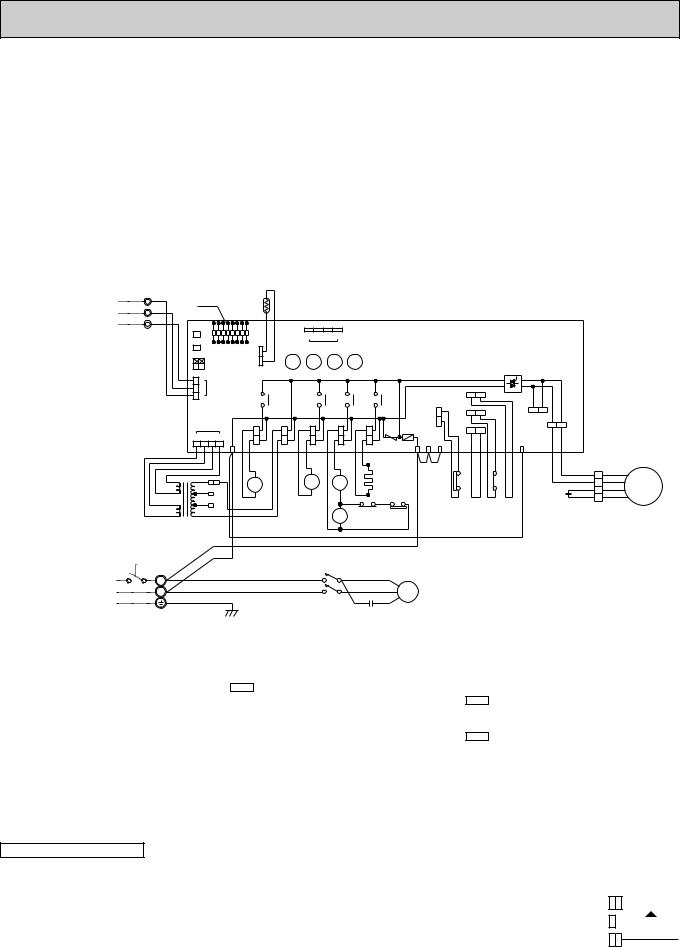
PUH-3VKAFT
SYMBOL |
NAME |
SYMBOL |
NAME |
SYMBOL |
NAME |
MC |
COMPRESSOR |
TB1,3 |
TERMINAL BLOCK |
X12<O.B> |
COMPRESSOR RELAY |
MF |
OUTDOOR FAN MOTOR (INNER THERMOSTAT) |
63H1 |
CONTROL HIGH PRESSURE SWITCH |
X13<O.B> |
SOLENOID COIL RELAY |
C1 |
FAN MOTOR CAPACITOR |
63H2 |
PROTECT HIGH PRESSURE SWITCH |
X14<O.B> |
SOLENOID COIL RELEY |
C2 |
COMPRESOR CAPACITOR |
O.B |
OUTDOOR CONTROLLER BOARD |
X16 |
HIGH PRESSURE RELAY |
TH |
PIPE TEMPERATURE THERMISTOR |
ZNR<O.B> |
SURGE ABSORBER |
SW1,2,3<O.B> |
CHECK,SERVICE SELECT SWITCH |
HC |
CRANKCASE HEATER |
F<O.B> |
FUSE(6.3A) |
LD1-LD8<O.B> |
CHECK,SERVICE LED |
52C |
CONTACTOR |
FC<O.B> |
FAN CONTROLLER |
CN3<O.B> |
CONNECTING WIRES |
21S4 |
4-WAY VALVE SOLENOID COIL |
X11<O.B> |
CRANKCASE HEATER RELAY |
|
INDOOR/OUTDOOR CONNECTOR |
21R |
BYPASS VALVE SOLENOID COIL |
T |
TRANSFORMER |
CN4T<O.B> |
TRANSFORMER CONNECTOR |
TO INDOOR UNIT CONNECTING WIRES DC 12V
POWER SUPPLY ~/N(1phase) 220V-240V 50Hz
1 |
YLW |
LED |
TH |
|
|
|
|
|
|
|
|
|
|
|
|
|
|
|
|
|
|
|
|
|
2 |
ORN |
|
|
|
|
|
|
|
|
|
|
|
|
|
|
|
|
|
|
|
|
|||
O.B |
|
|
|
|
|
|
|
|
|
|
|
|
|
|
|
|
|
|
|
|
|
|||
|
|
|
|
|
|
|
|
|
|
|
|
|
|
|
|
|
|
|
|
|
|
|||
3 |
BRN |
|
|
|
|
|
|
|
|
|
|
|
|
|
|
|
|
|
|
|
|
|
|
|
|
|
|
|
|
|
|
|
|
|
|
|
|
|
|
|
|
|
|
|
|
|
|
||
TB3 |
SW1 |
|
|
|
|
4 3 2 1 |
|
|
|
|
|
|
|
|
|
|
|
|
|
|
|
|||
SW2 |
|
|
|
|
|
|
|
|
|
|
|
|
|
|
|
|
|
|
|
|||||
|
|
|
|
|
|
|
|
|
|
|
|
|
|
|
|
|
|
|
|
|
||||
|
|
LD1 LD2 LD3 LD4 LD5 LD6 LD7 LD8 |
|
|
CN4 |
|
|
|
|
|
|
|
|
|
|
|
|
|
|
|
|
|||
|
|
SW3 |
|
|
|
|
|
|
|
|
|
|
|
|
|
|
|
|
|
|
||||
|
|
|
|
|
|
|
|
|
|
|
|
|
|
|
|
|
|
|
|
|
|
|||
|
|
OFF |
CN2 |
X14 |
|
X13 |
X12 |
X11 |
|
|
|
|
|
|
|
|
|
|
|
|
|
|
||
|
|
|
|
|
|
|
|
|
|
|
|
|
|
|
|
|
|
|||||||
|
|
21 ON |
|
|
|
|
|
|
|
|
|
|
|
|
|
|
|
|
|
|
|
|
|
|
|
|
3 |
CN3 |
|
|
|
|
|
|
|
|
|
|
|
|
|
|
|
|
|
|
|
|
|
|
|
2 |
|
|
|
|
|
|
|
|
|
|
|
|
26C |
|
|
|
|
|
|
|
|
|
|
|
1 |
|
X14 |
|
|
X13 |
X12 |
|
X11 |
|
|
|
|
F.C |
|
|
|
|
|
||||
|
|
|
|
|
|
|
|
|
|
|
|
|
|
|
|
|||||||||
|
|
|
|
|
|
|
|
|
|
|
|
|
|
63H1 |
63H2 |
|
|
MF2 |
|
|
|
|
|
|
|
|
|
|
|
|
|
|
|
|
|
|
|
|
|
|
|
|
MF1 |
|
|
|
|||
|
|
CN4T |
|
|
|
|
|
|
|
|
|
|
|
|
51CM |
|
|
|
|
|
|
|
||
|
|
4 3 2 1 4 |
|
|
|
|
|
|
|
|
|
|
|
|
|
|
|
|
|
|
|
|
||
|
RED |
SV |
TRF |
|
21S4 |
|
52C |
CH |
ZNR F R |
S T |
|
|
|
5 |
|
|
|
|
|
|||||
|
|
|
RED RED |
BLU |
BLU |
GRY |
GRY |
WHT |
WHT |
|
|
|
|
|
BRN BRN |
YLW |
YLW VLT VLT |
YLW YLW BLU |
|
|
|
|
|
|
|
RED |
|
|
|
|
|
|
|
|
|
|
|
|
|||||||||||
|
BRN |
|
|
|
|
|
|
BLU BLU |
|
|
|
|
|
|||||||||||
|
BRN |
|
|
|
|
|
|
|
A1 |
|
|
|
|
|
|
|
|
1 |
|
WHT |
3 |
WHT |
|
|
|
|
|
|
|
|
21 |
|
|
HC |
|
|
|
|
|
|
|
|
|||||||
|
AC |
YLW |
21R |
|
|
52C |
|
|
|
|
63H1 |
|
X16 |
|
BLU |
BLU |
MF |
|||||||
|
ORN 240V |
|
|
S4 |
|
|
|
|
|
|
|
|
|
5 |
|
ORNRED |
4 |
ORNRED |
||||||
|
12.3V |
|
|
|
|
|
A2 |
|
GRY |
|
|
|
|
|
C1 |
2 |
||||||||
|
|
RED 230V |
WHT |
|
|
|
|
GRY |
|
|
|
|
|
|
|
|
1 |
|
|
|||||
|
AC12.3V |
|
220V |
|
|
|
X167 6 X16 2 63H2 |
|
|
|
|
|
|
|
|
|
|
|||||||
|
T |
WHT |
|
|
|
|
|
|
|
|
|
|
|
|
|
|||||||||
|
|
|
|
|
|
|
|
8 |
GRY |
|
|
|
|
|
|
|
|
|
|
|
|
|||
|
|
|
BLU |
RED |
|
|
|
|
|
|
|
|
|
|
|
|
|
|
|
|
|
|
|
|
|
|
|
|
|
|
|
|
|
|
|
|
|
|
|
|
|
|
|
|
|
|
|
|
|
|
TB1 |
|
|
RED |
|
L1/1 |
T1/2 BLU |
|
|
R |
|
|
|
|
|
|
|
|
|
|
|
|||
|
L |
|
|
|
|
|
|
|
|
|
|
|
|
|
|
|
|
|||||||
|
|
|
BLU |
|
|
|
|
|
WHT |
|
C |
|
|
|
|
|
|
|
|
|
|
|
|
|
|
N |
|
|
|
L3/5 |
T2/6 |
|
|
MC |
|
|
|
|
|
|
|
|
|
|
|||||
|
|
|
|
|
|
RED RED |
S |
|
|
|
|
|
|
|
|
|
|
|
||||||
|
|
GRN/YLW |
|
|
|
52C |
|
C2 |
|
|
|
|
|
|
|
|
|
|
|
|
||||
|
|
|
|
|
|
|
|
|
|
|
|
|
|
|
|
|
|
|
|
|
||||
Main functions of LED (when both Nos.1 and 2 of SW3 are “OFF”)
LED No. |
Output display |
( |
light |
) |
( |
flash |
) |
|
|
Check display |
|
||||
LD1 |
Compressor indoor command |
– |
|
|
|||
LD2 |
Heating indoor command |
|
– |
|
|
||
LD3 |
63H1 |
ON |
|
Pipe sensor short/open |
|
||
LD4 |
Compressor |
ON |
|
63H2 functions |
|
|
|
LD5 |
Outdoor fan |
ON |
|
– |
|
|
|
LD6 |
4-way valve |
ON |
|
– |
|
|
|
LD7 |
Bypass valve |
ON |
|
TH overheat protection |
|
||
LD8 |
Crankcase heater |
ON |
|
Defective input |
|
|
|
NOTE : If the operation stops to function of the protection device, the check display flashes.
CAUTION FOR SERVICING
How to use SW1 and 2
●Pressing SW1 erases the past check contents loaded on the
microcomputer.
●The output display (light) remains lit during operation but pressing SW2 displays the past check contents in flashing mode. Pressing the switch again returns to output display (light).
●Connect the lead wires accordling to the color indication of sticker on the compressor terminal.
|
|
|
When power supply is 220V |
|||||||
CAUTIONS FOR POWER SUPPLY WIRING |
|
|
||||||||
|
|
RED |
|
|
|
|
|
WHITE |
||
●Since LD8 lights when normal power is turned “ON”, check the power supply. |
220V |
|
|
|
|
|||||
ORANGE |
|
|
|
|
|
|
|
|||
Since the transformer (T) is connected with 240V power, if 220V or 230V power is used, change the wiring connection |
|
|
|
|
|
|
|
|||
230V |
|
|
|
|
|
|
||||
in the following procedure. |
YELLOW |
|
|
|
|
|
|
|
||
|
|
|
240V |
|
|
|
|
|
|
|
CAUTION FOR INDOOR AND OUTDOOR CONNECTING WIRES |
|
|
|
|
|
|
|
|
|
|
|
|
|
|
|
|
|
|
|||
●Since the indoor and outdoor connecting wires has polarity, make sure to connect the same terminal numbers (1,2,3) for indoor and outdoor units.
15
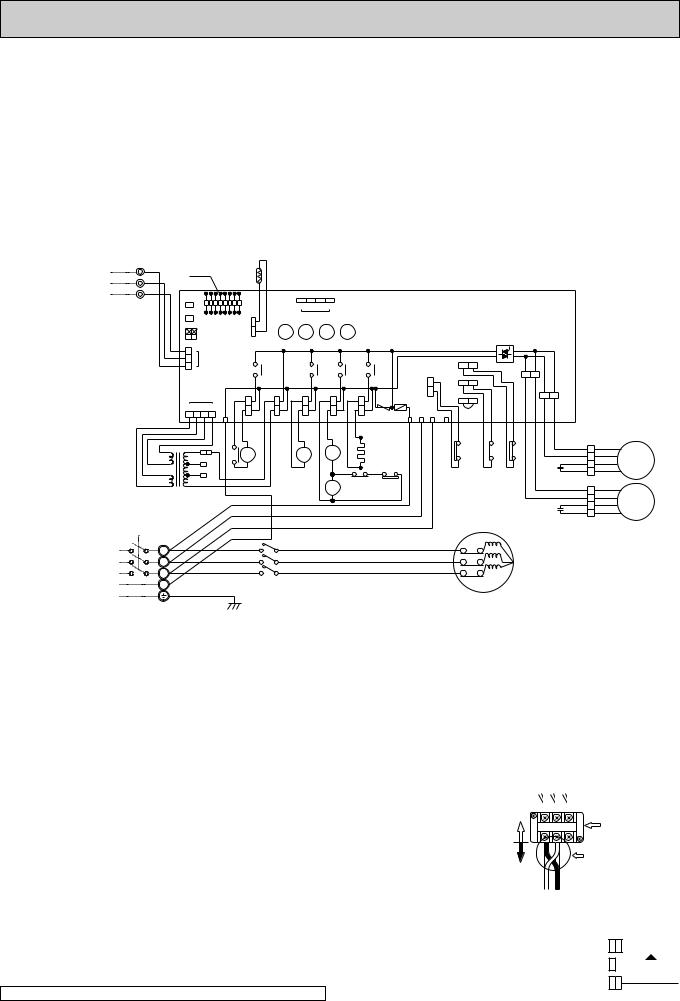
PUH-5YKSAFT
SYMBOL |
NAME |
SYMBOL |
NAME |
SYMBOL |
NAME |
MC |
COMPRESSOR |
TB1,3 |
TERMINAL BLOCK |
X12<O.B> |
COMPRESSOR RELAY |
MF1,2 |
OUTDOOR FAN MOTOR (INNER THERMOSTAT) |
63H1 |
CONTROL HIGH PRESSURE SWITCH |
X13<O.B> |
SOLENOID COIL RELAY |
C1,2 |
FAN MOTOR CAPACITOR |
63H2 |
PROTECT PRESSURE SWITCH |
X14<O.B> |
SOLENOID COIL RELEY |
TH |
PIPE TEMPERATURE THERMISTOR |
26C |
DIS.CHARGE THERMAL SWITCH |
CN3<O.B> |
CONNECTING WIRES |
HC |
CRANKCASE HEATER |
O.B |
OUTDOOR CONTROLLER BOARD |
|
INDOOR/OUTDOOR CONNECTOR |
49C |
INTERNAL THERMOSTAT FOR MC |
ZNR<O.B> |
SURGE ABSORBER |
CN4T<O.B> |
TRANSFORMER CONNECTOR |
52C |
CONTACTOR |
F<O.B> |
FUSE(6.3A) |
SW1,2,3<O.B> |
CHECK,SERVICE SELECT SWITCH |
21S4 |
4-WAY VALVE SOLENOID COIL |
FC<O.B> |
FAN CONTROLLER |
LD1-LD8<O.B> |
CHECK,SERVICE LED |
21R |
BYPASS VALVE SOLENOID COIL |
X11<O.B> |
CRANKCASE HEATER RELAY |
51CM<O.B> |
JUMPER CONNECTOR |
X16 |
HIGH PRESSURE RELAY |
T |
TRANSFORMER |
|
|
TO INDOOR UNIT CONNECTING WIRES DC 12V
POWER SUPPLY 3N~(3phase 4wires) 380/220V-415/240V 50Hz
1 |
YLW |
LED |
TH |
|
2 |
ORN |
|||
O.B |
||||
|
||||
3 |
BRN |
|
||
|
|
TB3 |
SW1 |
|
|
|
|
4 3 2 1 |
|
|
|
|
|
|
|
|
|
|
|
|
|
|
SW2 |
|
|
|
|
|
|
|
|
|
|
|
|
|
|
|
|
|
|||
|
|
|
|
|
|
|
|
|
|
|
|
|
|
|
|
|
|
|||
|
LD1 LD2 LD3 LD4 LD5 LD6 LD7 LD8 |
|
CN4 |
|
|
|
|
|
|
|
|
|
|
|
|
|
||||
|
SW3 |
|
|
|
|
|
|
|
|
|
|
|
|
|
|
|||||
|
|
|
|
|
|
|
|
|
|
|
|
|
|
|
|
|
||||
|
OFF |
CN2 |
X14 |
X13 |
X12 |
X11 |
|
|
|
|
|
|
|
|
|
|
||||
|
|
|
|
|
|
|
|
|
|
|
|
|||||||||
|
21 ON |
|
|
|
|
|
|
|
|
|
|
|
|
|
|
|
|
|
|
|
|
3 |
|
|
|
|
|
|
|
|
|
|
|
|
|
|
|
|
|
|
|
|
2 CN3 |
|
|
|
|
|
|
|
|
|
|
|
|
26C |
|
|
|
|
|
|
|
1 |
|
|
|
X14 |
|
X13 |
X12 |
|
X11 |
|
|
|
|
|
F.C |
||||
|
|
|
|
|
|
|
|
|
|
|
|
|
|
|
|
|
|
|
|
MF2 |
|
CN4T |
|
|
|
|
|
|
|
|
|
63H1 |
63H2 |
|
|
|
|
|
|||
|
|
|
|
|
|
|
|
|
|
|
|
|
51CM |
|
|
|
|
|||
|
4 3 2 1 4 |
|
|
|
|
|
|
|
|
|
|
|
|
|
|
|
|
|||
|
|
SV |
TRF |
21S4 |
52C |
|
CH ZNRFR |
S |
T |
5 |
|
|
|
|
|
|||||
RED |
|
|
|
|
|
|
|
|
|
|||||||||||
|
|
RED RED |
BLU BLU |
GRY |
GRY |
BLK |
BLK |
|
|
|
|
BRN BRN |
VLT |
VLT |
|
BLK |
BLK |
|||
RED |
|
|
|
|
|
|
1 |
|||||||||||||
BRN |
|
|
|
|
|
|
||||||||||||||
BRN |
|
|
13 |
|
|
|
|
A1 |
|
|
|
|
|
|
|
|
|
|
|
|
YLW |
|
|
|
|
|
HC |
|
|
|
63H1 |
|
X16 |
|
|||||||
AC |
52C |
21R |
|
21 |
52C |
|
|
|
|
|
26C |
|||||||||
ORN 240V |
|
|
|
|
|
|
||||||||||||||
12.3V |
14 |
|
|
S4 |
|
A2 |
|
|
|
|
|
|
|
|
|
5 |
C1 |
|||
|
RED 230V |
RED |
WHT |
|
|
|
GRY |
|
GRY |
|
|
|
|
|
|
|
||||
AC12.3V |
|
220V |
|
|
|
7 6 |
|
2 |
63H2 |
|
|
|
|
|
|
|
|
|||
|
|
|
|
|
X16 |
|
|
|
|
|
|
|
|
|||||||
|
|
WHT |
|
|
|
|
|
|
|
|
|
|
|
|||||||
|
T |
|
|
|
|
|
X16 |
|
|
|
|
|
|
|
|
|
|
|||
|
|
RED |
|
|
|
8 |
|
GRY |
|
|
|
|
|
|
|
|
||||
|
|
|
|
|
|
|
|
|
|
|
|
|
|
|
||||||
|
|
|
|
|
|
|
|
|
|
|
|
|
|
|
|
|
|
C2 |
||
|
|
|
WHT |
|
|
|
|
|
|
|
|
|
|
|
|
|
|
|
||
|
|
|
|
|
|
|
|
|
|
|
|
|
|
|
|
|
|
|
||
|
|
|
BLK |
|
|
|
|
|
|
|
|
|
|
|
MC |
|
|
|||
TB1 |
|
|
BLU |
|
|
|
|
|
|
|
|
|
|
|
49C |
|
|
|
|
|
|
|
RED L1/1 |
T1/2 |
|
|
|
|
RED |
|
|
|
T1 |
|
|
|
|
||||
L1 |
|
|
|
|
|
|
|
|
|
|
|
|
|
|
||||||
|
|
WHTL2/3 |
T2/4 |
|
|
|
|
WHT |
|
|
|
T2 |
|
|
|
|
|
|||
L2 |
|
|
|
|
|
|
|
|
|
|
|
|
|
|
||||||
|
|
BLU L3/5 |
T3/6 |
|
|
|
|
BLU |
|
|
|
|
T3 |
|
|
|
|
|
||
L3 |
|
|
|
|
|
|
|
|
|
|
|
|
|
|
|
|||||
|
|
|
52C |
|
|
|
|
|
|
|
|
|
|
|
|
|
|
|
||
N |
|
|
|
|
|
|
|
|
|
|
|
|
|
|
|
|
|
|
||
|
|
|
|
|
|
|
|
|
|
|
|
|
|
|
|
|
|
|
|
|
|
GRN/YLW |
|
|
|
|
|
|
|
|
|
|
|
|
|
|
|
|
|
|
|
MF1
WHT 3 WHT BLU 4 BLU RED 2 RED ORN 1 ORN
WHT 3 WHT BLU 4 BLU BRN 2 RED YLW 1 ORN
MF1
MF2
Main functions of LED (when both Nos.1 and 2 of |
SW3 |
are “OFF”) |
|
|
|
How to use SW1 and 2 |
|
|
|
|
|
|
|
|
|
|
|
|
|
|
|||||||||||
|
|
|
|
|
|
|
|
|
|
|
●Pressing |
|
|
|
erases the past check contents loaded on the |
||||||||||||||||
|
|
|
( |
) |
|
|
( |
|
) |
|
SW1 |
|
|||||||||||||||||||
LED No. |
Output display |
light |
|
|
|
|
Check display |
flash |
|
|
microcomputer. |
|
|
|
|
|
|
|
|
|
|
|
|
|
|
||||||
LD1 |
Compressor indoor command |
|
Auti-phase detect |
|
|
|
|
|
|
|
|
|
|
|
|
|
|
|
|
|
|||||||||||
|
|
|
|
●The output display (light) remains lit during operation but |
|||||||||||||||||||||||||||
LD2 |
Heating indoor command |
|
|
|
Missing-phase detect |
|
|
||||||||||||||||||||||||
|
|
|
|
|
pressing |
|
SW2 |
|
displays the past check contents in flashing |
||||||||||||||||||||||
LD3 |
63H1 |
ON |
|
|
|
Pipe sensor short/open |
|
|
mode. Pressing the switch again returns to output display |
||||||||||||||||||||||
LD4 |
Compressor |
ON |
|
|
|
63H2 functions |
|
|
|
(light). |
|
|
|
|
|
|
|
|
|
|
|
|
|
|
|||||||
LD5 |
Outdoor fan |
ON |
|
|
|
|
– |
|
|
|
|
|
|
|
|
Power line reconnection procedure |
|||||||||||||||
LD6 |
4-way valve |
ON |
|
|
|
26C functions |
|
|
|
|
|
|
|
|
In case of reverse rotation |
|
|
|
|||||||||||||
LD7 |
Bypass valve |
ON |
|
|
|
RT overheat protection |
|
|
|
|
|
|
|
|
|
|
|
|
|
|
|
|
|
|
|
|
|
|
|||
|
|
|
|
|
|
|
|
|
|
|
|
|
|
|
|
|
|
|
|
|
|
|
|
|
|||||||
LD8 |
Crankcase heater |
ON |
|
|
|
Defective input |
|
|
|
|
|
Unit side |
|
|
|
|
|
|
Outdoor unit |
||||||||||||
|
|
|
|
|
|
|
|
L1 L2L3 |
|||||||||||||||||||||||
|
|
|
|
|
|
|
|
|
|
|
|
|
|
||||||||||||||||||
NOTE : If the operation stops to function of the protection device, the check display flashes. |
|
|
wiring |
||||||||||||||||||||||||||||
|
|
terminal |
|||||||||||||||||||||||||||||
|
|
|
|
|
|
|
|
|
|
|
|
||||||||||||||||||||
|
|
|
|
|
|
|
|
|
|
|
|
|
|
|
|
|
|
|
|
|
|
|
charge 2 out of 1. |
||||||||
CAUTION FOR SERVICING |
|
|
|
|
|
|
|
|
|
|
|
|
|
|
|
|
|
|
|
|
|
|
|||||||||
|
|
|
|
|
|
|
|
|
|
|
|
|
|
|
|
|
|
|
|
|
|
|
|
2 and 3. |
|
|
|
||||
Connect the lead wires accordling to the color indication of sticker on the compressor terminal. |
|
|
Field wiring |
|
|
|
|
|
|
|
|
|
|||||||||||||||||||
|
|
|
|
|
|
|
|
(This example shows |
|||||||||||||||||||||||
● |
|
|
|
|
|
|
|
|
|
|
|
|
|
|
|
|
|
|
|
|
|
|
|
|
|
|
|
|
|
|
|
|
|
|
|
|
|
|
|
|
|
|
|
|
|
|
|
|
|
|
|
|
|
|
|
reconnection of 1 |
|||||||
CAUTIONS FOR POWER SUPPLY WIRING |
|
|
|
|
|
|
|
|
|
Change thie side |
|
|
|
|
|
and 2.) |
|
|
|
||||||||||||
|
|
|
|
|
|
|
|
|
|
|
|
|
|
|
|
|
|
|
1 2 3 |
|
|
|
|
|
|
|
|
||||
Making wiring connection in anti-phase or missing phase “L2” or “L3” causes the protection device incorporated in the |
|
|
|
|
|
|
|
|
|
||||||||||||||||||||||
|
|
|
|
|
|
|
|
|
|
|
|
|
|
||||||||||||||||||
● |
|
|
|
|
|
|
|
|
|
|
|
|
|
|
|
|
|
|
|
|
|
|
|
|
|
|
|
|
|
|
|
microcomputer to function resulting in LD1 or LD2 shown in the table above to flash and prevents the compressor |
|
|
When power supply is 220V |
||||||||||||||||||||||||||||
operation. If phase “L1” or “N” is missing it causes all displays to go out. Under normal condition LD8 light when power |
|
|
|||||||||||||||||||||||||||||
|
|
|
|
|
|
|
|
|
|
|
|
|
|
||||||||||||||||||
is turned “ON”. If anti-phase connection is to be used, change connections of 2 out of 3 power lines (field wiring side) |
|
|
|
|
RED |
|
|
|
|
WHITE |
|
||||||||||||||||||||
|
|
220V |
|
|
|
|
|||||||||||||||||||||||||
contained in the power supply terminal block (TB1) of the outdoor unit as shown at the right upper. |
|
|
|
|
|
|
|
|
ORANGE |
|
|
|
|
|
|
|
|
||||||||||||||
|
|
|
|
|
|
|
|
|
|
|
|
|
|
|
|
||||||||||||||||
Since the transformer (T) is connected with 240V power, if 220V or 230V power is used, change the wiring connection |
|
|
230V |
|
|
|
|
|
|
|
|||||||||||||||||||||
|
|
|
|
|
|
|
|
|
|
|
|
|
|
||||||||||||||||||
in the following procedure. |
|
|
|
|
|
|
|
|
|
|
|
|
|
|
|
|
|
YELLOW |
|
|
|
|
|
|
|
||||||
|
|
|
|
|
|
|
|
|
|
|
|
|
|
|
|
240V |
|
|
|
|
|
|
|
||||||||
|
|
|
|
|
|
|
|
|
|
|
|
|
|
|
|
|
|
|
|
|
|
|
|
|
|
|
|
|
|
|
|
CAUTION FOR INDOOR AND OUTDOOR CONNECTING WIRES
●Since the indoor and outdoor connecting wires has polarity, make sure to connect the same terminal numbers (1,2,3) for indoor and outdoor units.
16
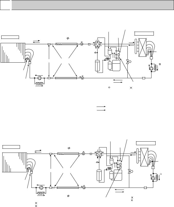
6 
 REFRIGERANT SYSTEM DIAGRAM
PLH-1.6KKHCFT/PUH-1.6VKAFT
Unit : mm
High pressure
control switch
Oil separator
Indoor unit
Indoor heat exchanger
Strainer
Indoor coil |
Restrictor |
thermistor |
valve |
(RT2) |
|
Distributor |
|
with |
|
strainer |
Capillary |
|
|
|
tube |
PLH-1.6 (O.D.3.2 I.D.1.6-r630)
Refrigerant pipe (option) 15.88mm( 5/8")
(with heat insulator)
Flexible tube
Flared connection
Refrigerant pipe (option) 9.52mm( 3.8")
3.8")
(with heat insulator)
4-way valve |
Service |
Outdoor unit |
|
port |
Outdoor heat exchanger |
|
|
Ball valve |
|
|
|
Strainer |
|
|
|
Service |
|
|
Outdoor coil |
port |
|
|
|
|
|
thermistor |
|
|
|
|
(TH) |
|
|
Bypass |
|
|
|
valve |
|
Accumulator |
|
Restrictor |
Capillary |
|
|
||
|
|
valve |
tube |
|
Compressor |
|
|
Ball valve |
Strainer |
|
High pressure |
||
|
(with service port) |
protect switch |
|
PUH-1.6 (O.D.3.2 I.D.1.8 -R600) |
Refrigerant flow in cooling |
R.V.coil |
|
Heating ON |
||
Refrigerant flow in heating |
||
Cooling OFF |
||
|
PKH-1.6FKHAFT/PUH-1.6VKAFT
PKH-3FKHAFT/PUH-3VKAFT
|
|
|
|
|
High pressure |
|
|
|
|
|
|
Oil separator |
control switch |
|
|
|
|
|
|
|
|
|
|
|
|
Refrigerant pipe |
4-way valve |
Service |
Outdoor unit |
|
|
Indoor unit |
|
(option) |
|
port |
Outdoor heat exchanger |
|
|
|
15.88mm( |
5/8") |
Ball valve |
|
|||
|
|
|
|
|
|||
|
|
(with heat insulator) |
Strainer |
|
|
|
|
|
|
|
|
|
|
|
|
|
|
Flexible tube |
|
|
|
|
|
Indoor |
|
|
|
Service |
|
|
Outdoor coil |
heat |
|
|
|
port |
|
|
|
|
|
|
|
|
thermistor |
||
exchanger |
|
|
|
|
|
|
|
|
|
|
|
|
|
(TH) |
|
|
|
|
|
|
|
|
|
|
Strainer |
Flared |
|
|
|
Bypass |
|
|
connection |
|
|
|
|||
|
|
|
|
valve |
|
||
|
|
|
|
|
|
|
|
|
|
|
|
Accumulator |
|
Restrictor |
Capillary |
|
|
|
|
|
|
||
Indoor coil |
Restrictor |
|
|
|
Compressor |
valve |
tube |
|
|
|
|
|
|||
thermistor |
valve |
|
|
|
|
|
|
|
|
|
|
|
|
||
(RT1) |
|
|
|
|
|
|
|
Distributor |
|
Refrigerant pipe |
Ball valve |
|
Strainer |
|
|
with |
|
|
|
||||
|
(option) |
|
(with service port) |
|
|
|
|
strainer |
|
|
|
|
|
||
Capillary |
9.52mm( |
3.8") |
|
|
|
|
|
|
|
PUH-1.6 (O.D.3.2 |
I.D.1.8 -r600) |
|
|||
|
(with heat insulator) |
High pressure |
|
||||
|
tube |
|
|
control switch |
PUH-3 (O.D.4.0 |
I.D.2.4 -r940) |
|
PKH-1.6 (O.D.3.2 |
I.D.1.6-r700) |
|
|
|
|
|
|
PKH-3 (O.D.4.0 |
I.D.2.2-r740) |
|
|
|
|
|
|
17
 Loading...