


KM400
Miele KM 400, KM 400-3, KM 412, KM 418, KM 418-1 Installation Instruction
...
Installation Instructions
Ceramic hobs
KM 400 / 400-3 / 412 / 418 / 418-1
Ceramic contact grill
KM 408-1 / 408-2
Open grill KM 410 / 411 / 411-3
Deep fat fryer KM 402 / 403
To avoid the risk of accidents
or damage to the machine
it is essential to read these
instructions before it is
installed and used for the first time.
M.-Nr. 04 930 397
en-GB

Warning and Safety instructions . . . . . . . . . . . . . . . . . . . . . . . . . . . . . . . . . . . . . 3
Building in ........................................................3
Additional safety notes on induction hobs / KM 418 / KM 418-1 ............4
Safety distance above the appliance .................................5
Safety distance between the KM 410 / KM 411 / KM 411-3 and a cooker hood
above it ........................................................5
Appliance dimensions. . . . . . . . . . . . . . . . . . . . . . . . . . . . . . . . . . . . . . . . . . . . . . 6
KM 400 / KM 400-3 / KM 408-1 / KM 408-2 / KM 412 .......................6
KM402/KM403...................................................7
KM 410 / KM 411 / KM 411-3..........................................8
KM 418 / KM 418-1 .................................................9
Worktop cut-out . . . . . . . . . . . . . . . . . . . . . . . . . . . . . . . . . . . . . . . . . . . . . . . . . . 10
Installation . . . . . . . . . . . . . . . . . . . . . . . . . . . . . . . . . . . . . . . . . . . . . . . . . . . . . . 11
Fitting the spacer bars and spring clamps ..............................11
Fixing the spacer bars ..............................................12
Granite worktops................................................12
Fixing the spring clamps ............................................12
Granite worktops................................................12
Building in the appliance ............................................13
General . . . . . . . . . . . . . . . . . . . . . . . . . . . . . . . . . . . . . . . . . . . . . . . . . . . . . . . . . 14
Electrical connection . . . . . . . . . . . . . . . . . . . . . . . . . . . . . . . . . . . . . . . . . . . . . 15
Contents
2
Building in
Fit wall units and the cooker hood
before fitting the ceramic hob, to
avoid damaging the hob.
~
The veneer or laminate coatings of
worktops (or adjacent kitchen units)
must be treated with 100 °C heat
resistant adhesive which will not
dissolve or distort. Any backmoulds
must be of heat-resistant material.
~
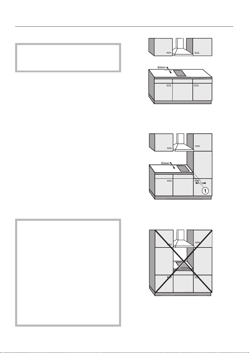
Ideally the hobs should be installed
with plenty of space on either side.
There may by a wall at the rear and a
wall or tall unit at one side. On the other
side, however, no unit or divider may
stand higher than the hob (see
illustrations).
~
An electric fryer must not be
installed next to a gas hob, as the gas
flames could ignite the fat in the fryer. It
is essential to maintain a safety
distance of at least 288 mm between
these two appliances.
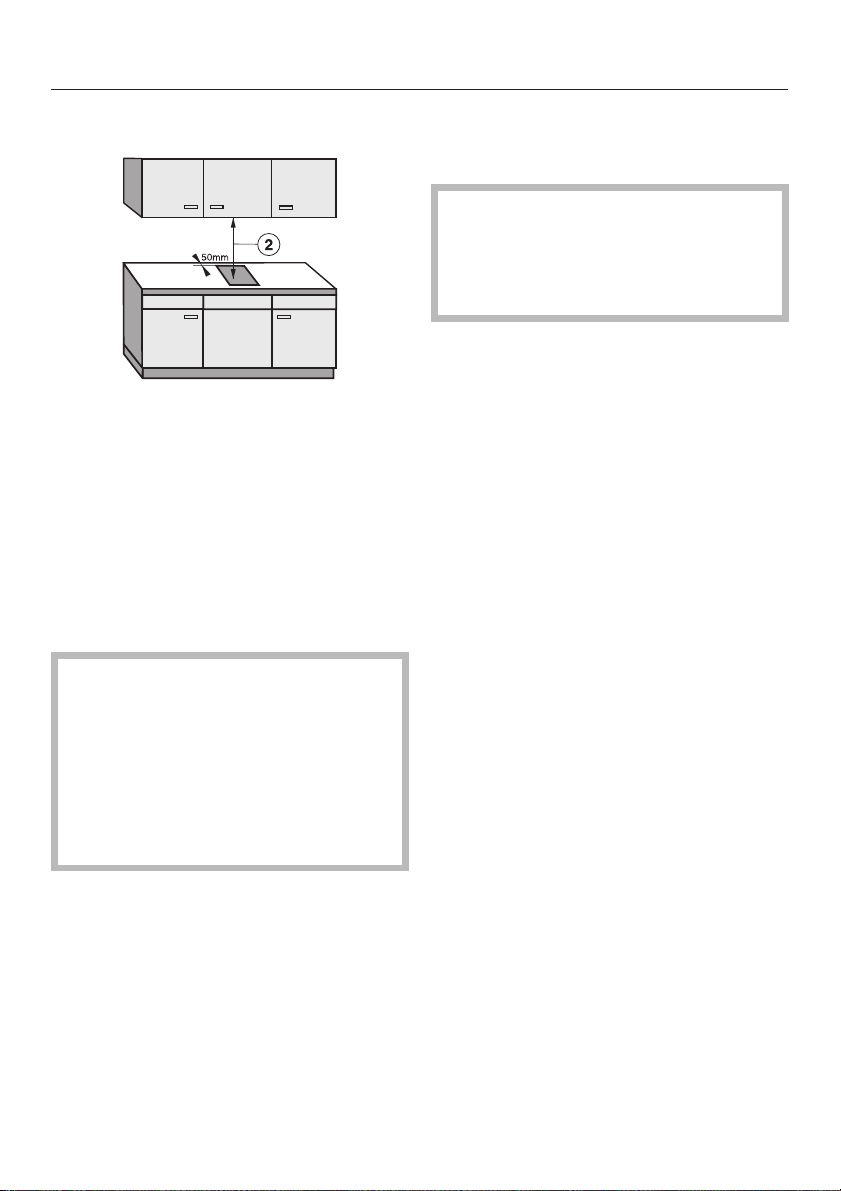
Due to the heat radiated by the hob
and to allow cooking fumes to
dissipate it is essential that a
minimum safety distance a is
maintained between the worktop
cut-out and adjacent kitchen units,
e.g. a tall unit, as follows:
40 mm = KM 400, 400-3, 402,
403, 412, 418, 418-1
50 mm = 408-1, 408-2
250 mm = KM 410, 411, 411-3
There must be a minimum safety
distance of 50 mm between the hob
and a back wall.
recommended
not recommended
not allowed!
Warning and Safety instructions
3

~
After installation of the hob ensure
that the connection cable is without
hindrance and that there is no
mechanical obstruction which could
damage it, such as a drawer.
~
These appliances must not be
installed over a dishwasher, washing
machine, tumble dryer, refrigerator,
fridge-freezer or freezer. The high
temperatures radiated by hobs could
damage the appliance below.
~
This equipment may only be used in
mobile installations such as ships,
caravans, aircraft etc. if a risk
assessment of the installation has been
carried out by a suitably qualified
engineer.
~
Spray canisters, aerosols and other
inflammable substances should not be
stored in a drawer under the hob.
Additional safety notes on induction
hobs / KM 418 / KM 418-1
~
This hob must not be installed
above an oven or cooker unless these
have a built-in cooling down fan.
~
To ensure adequate ventilation for
the electronic unit on the hob an interim
shelf must not be fitted underneath
hobs with induction heating.
Warning and Safety instructions
4
Safety distance above the appliance
A minimum safety distance b must be
maintained between the hob and the
cooker hood above it. See the
manufacturer’s operating and
installation instructions for details. For
any flammable objects, e.g utensil rails,
wall units etc. a minimum safety
distance of at least 760 mm should be
maintained between it and the hob
below.
When two or more appliances are
installed together below a cooker
hood, e.g. a combiset and a gas
wok combiset, which have different
safety distances given in their
installation instructions you should
select the greater distance of the
two.
Safety distance between the KM 410 /
KM 411 / KM 411-3 and a cooker
hood above it
For safety reasons, the minimum
safety distance between the KM410/
KM 411 / KM 411-3 Open grill and a
cooker hood above it, is the same as
for gas hobs, i.e. 650 mm.
~
The KM 410, 411, 411-3 should not
be used in conjunction with a cooker
hood that uses paper or carbon filters.
~
The KM 410, 411, 411-3 should not
be used with a recirculating cooker
hood.
~
When placing the KM 410, 411,
411-3 below a cooker hood, the outlet
system of the cooker hood must be
metallic throughout its length and be
heat proof.
~
The cooker hood outlet ducting must
be in compliance with national and
local building regulations.
~
Should any additional mechanical
ventilation be present then the effect of
this additional ventilation on the
combustion and flame performance of
any existing appliances must be
determined before any cooking
appliances are used.
~
All grease filters must be cleaned
regularly. Fat build up in the filters is a
potential fire hazard.
~
Never leave the grill unattended
when in use. It is possible for the food
being grilled to catch fire.
All dimensions in this instruction book
are given in mm.
Keep these instructions in a safe place
and pass them on to any future user.
Warning and Safety instructions
5
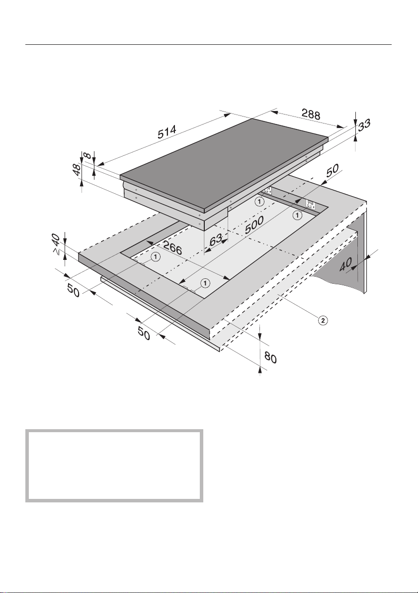
KM 400 / KM 400-3 / KM 408-1 /
KM 408-2 / KM 412
a Spring clamps
b Protective shelf
(KM 408-1 / KM 408-2 only)
A protective shelf and a front panel
must be fitted underneath KM 408-1
and KM 408-2 to ensure that the
underside of the appliance is not
accessible after installation.
~
Ensure that the connection cable
cannot come into contact with the
underside of the appliance.
~
A minimum distance of 80 mm is
required between the upper surface of
the worktop and the protective shelf
~
A gap of 40 mm must be maintained
between the shelf and the rear wall.
Appliance dimensions
6
 Loading...