


Technical data
Piling and drilling rig
LRB 255
Concept and characteristics
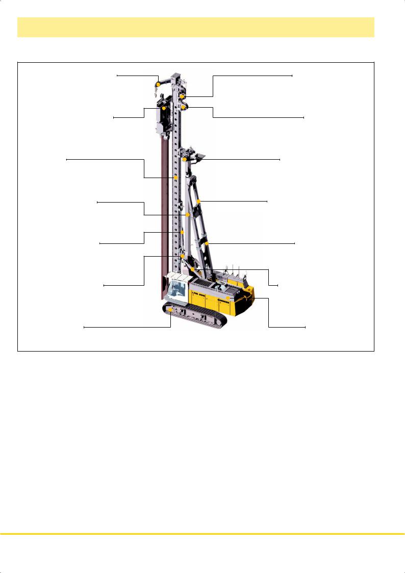
Leader top for auxiliary rope |
Rope crowd system |
Tool with quick connection |
Auxiliary winch |
Leader |
Lateral inclination device |
Leader support arm |
Longitudinal inclination device |
Vertical travel device |
Support arm brace |
Leader rotation device |
Radius adjustment device |
Undercarriage |
Uppercarriage |
•High engine output with automatic engine speed control
•Controlled entirely from cab
•Sturdy and solid rig design
•Wide longitudinal and lateral supporting system on the basic machine through triangles
•High push and pull forces
•High torque
•Completely self–rigging (no auxiliary machines required)
•Large range of working tools (all piling and drilling works can be performed)
•Stepless leader inclination 1:6 forward – 1:3 backward depending on type of equipment
•Leader swing range ± 90º
•Increase of effective leader length (3 m) via vertical travel device
•Automatic vertical alignment
•High alignment forces
•Simultaneous control of several movements via Load–sensing multi–circuit hydraulics
•Quick change of equipment possible through quick connection
•Equipment design according to latest European regulations and standards
•High manufacturing quality through quality control by PDE–system
2 LRB 255

Transport dimensions and weights
|
22085 |
|
3200 |
|
|
|
1245 |
400 |
3950 |
|
|
|
900 |
|
7725 |
5890 |
8470 |
3490 |
|
Transport with leader
includes the basic machine (ready for operation) with leader, without working tools (such as rotary, Kelly bar etc.) and without counterweight.
Dimensions and weights
Leader length |
|
|
|
21.2 m |
|
24.2 m |
|
27.2 m |
|
|
30.2 m |
|||
|
|
|
|
|
|
|||||||||
Weight complete |
|
|
|
|
|
|
|
|
|
|
|
|||
without counterweight* |
|
|
68.3 t |
|
|
69.4 t |
|
|
70.6 t |
|
|
|
71.8 t |
|
|
|
|
|
|
|
|
|
|||||||
|
|
22085 |
|
|
|
2850 |
|
|
|
|
|
|
|
|
1670 |
Transport leader |
|
|
Dimensions and weights |
|
|
||
includes the leader without working tools |
|
|
Leader length |
21.2 m |
24.2 m |
27.2 m |
30.2 m |
(such as rotary, Kelly bar etc.). |
|
|
Weight |
27.3 t |
28.4 t |
29.6 t |
30.8 t |
7150 |
3200 |
|
|
|
|
|
|
1245 |
|
3300 |
|
|
|
|
1370 |
|
|
|
|
|
|
|
|
|
900 |
400 |
|
3070 |
|
800 |
|
|
1690 |
|
|
|
|||
|
|
|
|
|
|
||
5890 |
3490 |
|
|
|
|
|
|
|
|
|
|
|
|
||
Transport basic machine |
|
|
Weights |
|
|
|
ready for operation |
|
|
Counterweight |
|
12.5 t |
|
|
|
|
||||
Basic machine* |
|
41 t |
|
|
|
|
|
|
|
|
|
||
|
|
|
|
|
|
|
*) Weights can vary with the fi nal confi guration of the machine.
LRB 255 3

Dimensions
Basic machine LRB 255
1:6 |
1:3 |
|
21200 (24000) [27200] {30200}
2.8°


2.8°
800 |
|
|
4000 |
4230 |
900 |
5700 |
|
4700 |
90°
90°
R4200
Technical data
Leader length |
|
|
|
|
|
|
|
|
|
|
|
|
21/24/27/30 m |
|||||||||||
|
|
|
|
|
|
|
|
|
|
|
|
|||||||||||||
Capacity hammer including cap plus pile |
|
|
|
|
|
|
|
|
|
|
|
30 t |
||||||||||||
|
|
|
|
|
|
|
|
|
|
|||||||||||||||
Max. hammer weight |
|
|
|
|
|
|
|
|
|
|
|
|
|
15 t |
||||||||||
|
|
|
|
|
|
|
|
|
|
|
|
|
||||||||||||
Max. pile weight |
|
|
|
|
|
|
|
|
|
|
|
|
|
|
|
|
|
15 t |
||||||
|
|
|
|
|
|
|
|
|
|
|
|
|
|
|
|
|
||||||||
Max. pull, leader on ground |
|
|
|
|
|
|
|
|
|
|
450 kN |
|||||||||||||
|
|
|
|
|
|
|
|
|||||||||||||||||
Max. torque |
|
|
|
|
|
|
|
|
|
|
|
|
|
|
300 kNm |
|||||||||
|
|
|
|
|
|
|
|
|
|
|
|
|||||||||||||
Working radius machine |
|
|
|
|
|
|
|
|
|
|
|
|||||||||||||
center of rotation — front edge leader |
|
|
|
|
3.2 — 4.9 m |
|||||||||||||||||||
|
|
|
|
|||||||||||||||||||||
Stepless rig inclination adjustment |
|
|
|
|
|
|
|
|
|
|
|
|||||||||||||
Lateral inclination |
|
|
|
|
|
|
|
± 1:20 |
||||||||||||||||
|
|
|
|
|
|
|
||||||||||||||||||
Forward inclination |
|
|
|
|
|
|
|
1:6 |
||||||||||||||||
|
|
|
|
|
|
|
||||||||||||||||||
Backward inclination |
|
|
|
|
|
1:3 |
||||||||||||||||||
|
|
|
|
|
||||||||||||||||||||
Vertical leader adjustment |
|
|
|
|
|
|
|
|
|
|
|
|||||||||||||
above ground level (depending on radius) |
|
|
|
|
|
|
|
|
|
|
|
|
3 m |
|||||||||||
|
|
|
|
|
|
|
|
|
|
|
||||||||||||||
below ground level (depending on leader length) |
|
|
|
|
|
|
|
|
|
|
|
5 m |
||||||||||||
|
|
|
|
|
|
|
|
|
|
|
||||||||||||||
Leader swing range |
|
|
± 90° |
|||||||||||||||||||||
|
|
|||||||||||||||||||||||
Operating weight and ground pressure
Total weight with 900 mm 3–web shoes |
|
|
80.8 t |
|
|
||||
Ground bearing pressure |
|
|
|
0.91 kg/cm2 |
|
|
|
||
The operating weight includes the basic machine LRB 255 (leader length 21.2 m, without working tools) and 12.5 t counterweight.
4 LRB 255

Technical data


 Engine
Power rating according to ISO 3046, 670 kW (898 hp) at 1900 rpm
Engine type |
|
MAN D 2842 LE |
|
|
|||
Fuel tank |
|
|
795 l capacity with continuous level |
|
|
||
indicator and reserve warning
Engine complies with NRMM exhaust certification EPA/CARB Tier 2.


 Hydraulic system
The main pumps are operated by a distributor gearbox. Axial piston displacement pumps work in open circuits supplying oil only when needed (flow control on demand).
The hydraulic pressure peaks are absorbed by the integrated automatic pressure compensation, which relieves the pump and saves fuel.
Pumps for working tools |
|
|
|
2x 400 l/min and 1x 350 l/min |
||||||
|
|
|
||||||||
Separate pump for kinematics |
|
|
|
|
|
|
129 l/min |
|||
|
|
|
|
|
|
|||||
Separate pump for crowd system |
|
|
|
300 l/min |
||||||
|
|
|
||||||||
Hydraulic oil tank |
|
|
|
|
1000 l |
|||||
|
|
|
|
|||||||
Max. working pressure |
|
|
|
|
|
350 bar |
||||
|
|
|
|
|
||||||
No auxiliary power packs are required as application specific hydraulics supply power to all components.
The cleaning of the hydraulic oils occurs via an electronically monitored pressure and return filter.
Any clogging is shown on the display in the cab.
The use of synthetic environmentally friendly oil is also possible.


 Control
The control system – developed and manufactured by Liebherr – is designed to withstand extreme temperatures and the many heavy– duty construction tasks for which this machine has been designed. Complete machine operating data are displayed on a high resolution monitor screen. A GSM modem allows for remote inquiry of machine data and error indications. To ensure clarity of the information on display, different levels of data are shown in enlarged lettering and symbols.
Control and monitoring of the sensors are also handled by this high technology system. Error indications are automatically displayed on the monitor in clear text. The machine is equipped with proportional control for all movements, which can be carried out simultaneously. Two joysticks are required for operation. Pedal control can be changed to hand control.
Options :
PDE : Process data recording


 Main winch with freefall
Line pull (effective) |
|
|
200 kN |
|||
|
|
|||||
Rope diameter |
|
|
|
|
30 mm |
|
|
|
|
|
|||
Line speed |
|
|
0 - 89 m/min |
|||
|
|
|||||


 Auxiliary winch
Line pull (effective) |
|
|
|
80 kN |
||||
|
|
|
||||||
Rope diameter |
|
|
|
|
|
|
20 mm |
|
|
|
|
|
|
|
|||
Drum diameter |
|
|
|
320 mm |
||||
|
|
|
||||||
Line speed |
|
|
0 - 48 m/min |
|||||
|
|
|||||||


 Crawlers
Propulsion through axial piston motor, hydraulically released spring loaded multi–disc brake, maintenance free crawler tracks, hydraulic chain tensioning device.
Drive speed |
|
|
0 – 1.5 km/h |
|||
|
|
|||||
Track force |
|
|
|
|
622 kN |
|
|
|
|
|
|||
Width of 3-web track shoes |
|
|
900 mm |
|||
|
|
|||||
 Swing
Swing
Consists of triple-row roller bearing with external teeth and two swing drives, fixed axial piston hydraulic motor, spring loaded and hydraulically released multi–disc holding brake, planetary gearbox and pinion. Selector for 3 speed ranges to increase swing precision. Swing speed from 0 – 4.5 rpm is continuously variable.


 Rope crowd system
Crowd force push/pull |
|
450/450 kN |
||||||
|
||||||||
Line pull (effective) |
|
|
|
|
150 kN |
|||
|
|
|
|
|||||
Rope diameter |
|
|
|
|
|
24 mm |
||
|
|
|
|
|
||||
Line speed |
|
|
|
0 - 87 m/min |
||||
|
|
|
||||||
The winches are noted for compact, easily mounted design. Propulsion is via a maintenance-free planetary gearbox in oil bath. Load support by the hydraulic system; additional safety factor by a spring–loaded, multi–disc holding brake. All line pull values are effective values. The efficiency factor of approx. 25% has already been deducted.


 Noise emission
Noise emissions correspond with 2000/14/EC directive on noise emission by equipment used outdoors.
LRB 255 5
 Loading...