


Product advantages |
LTM 1500-8.1 |
mobile crane |
|
Max. lifting capacity: 500 t at 3 m radius
Max. height under hook: 145 m with lattice luffing jib Max. radius: 108 m with lattice luffing jib
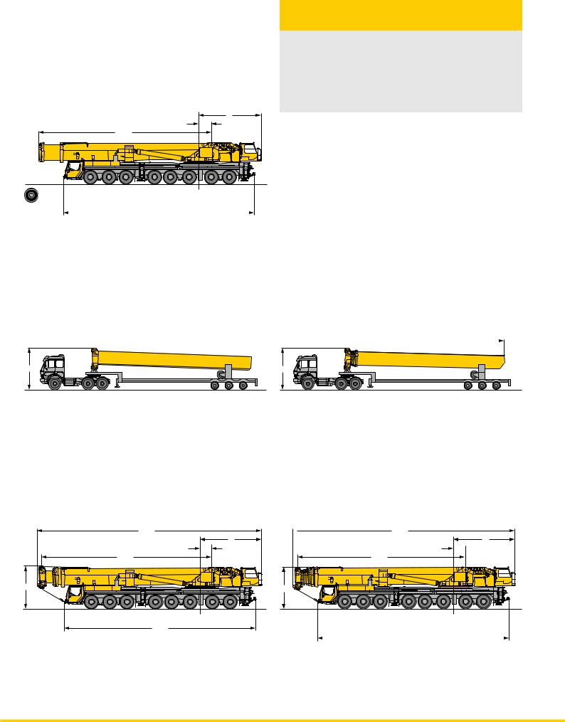
The variable telescoping boom system
• 96 t total weight incl. 50 m telescopic boom and permanent outrigger system
• Boom change device with hoisting and displacement mechanism on low loader
• Quick Connection for the dismantling of the telescopic boom (10 t axle load)
• Quick Connection for the dismantling of the superstructure (6 t axle load)
6 |
1.2 |
16.6 |
|
10.6 t |
10.6 t |
10.6 t |
11.8 t |
11.8 t |
||
|
10.6 t |
|
11.8 t |
|
11.8 t |
||
14.00 R25 |
|
|
18.4 |
|
|
|
|
|
|
|
|
|
|
|
|
+ or +
4 |
Tele 3 |
4 |
 15.3
15.3 
Tele 3 + 4 + 5 + 6
= =
|
|
|
|
21.6 |
|
|
6 |
|
|
|
|
|
|
|
|
|
|
|
|
|
|
|
1.2 |
|
|
|
16.4 |
|
|
|
|
4 |
50 m |
||||||
|
12 t |
12 t |
12 t |
12 t 12 t |
12 t |
12 t |
12 t |
|
|
|
|
18.4 |
|
|
|
8 421.3 m6
 1.2
1.2
16.1
4
14.7 t |
14.7 t |
14.7 t |
12.5 t |
12.5 t |
||
14.7 t |
|
12.5 t |
|
12.5 t |
||
|
|
|
18.4 |
|
|
|
|
|
|
|
|
|
|
2 |
LTM 1500-8.1 |
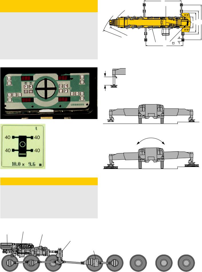
Setting on outriggers – quick, convenient and safe
•Permanent supporting pads
•Supporting rams with 500 mm travel
•Automatic levelling of the crane during the supporting procedure
•2 x 9° lateral inclination, even with locked suspension
•Inclinometer (electronic display of inclination) with two indicators on the carrier and one display on the LICCON monitor
•Indicators of supporting forces on the carrier and on the LICCON monitor
•Control of sliding outriggers with display of the state of extension on the LICCON monitor (optional)
10
R |
|
|
6.25 |
|
= 6.6 |
3 |
5.2 |
9.6 |
|
|
R |
= |
R |
= |
15 |
R |
|
|
|
|
|
|
|
|
||||
|
16 |
|
|
. |
|
|
1 ,2 |
|
|
. |
|
|
|
|
|||
|
|
|
= |
|
|
. |
||
|
|
25 |
|
|
7 |
|
|
2 |
|
|
|
|
|
|
= |
|
|
|
|
|
|
|
15 |
R |
|
|
|
|
|
|
|
|
0,7. |
||
|
|
|
|
|
|
|
||
|
|
|
|
|
|
10 |
|
|
|
|
|
|
|
|
|
|
|
500
Robust drive concept
•4 axles permanently driven (1st, 2nd, 4th and 5th axle)
•6 axles are steered;
independent steering of axles 7 and 8
•Automated gear system ZF-TC-TRONIC with converter and retarder, 12 forward and 2 reversed speeds, automated control
•Transfer case
•Driving axles with longitudinal differential locks
Diesel engine |
Transmission |
D9508 A7 |
|
radiator |
ZF-TC-TRONIC |
transfer case
eddy-current brake
1st axle |
2nd axle |
3rd axle |
4th axle |
5th axle |
6th axle |
7th axle |
8th axle |
driven |
driven |
non driven |
driven |
driven |
non driven |
non driven |
non driven |
steered |
steered |
steered |
steered |
non steered |
non steered |
steered |
steered |
|
|
|
|
|
|
|
|
LTM 1500-8.1 |
3 |

Outstanding boom technology
•Focal points of the new boom technology:
-oviform boom profile
-patented internal interlocking system of the telescopes
-automatic telescoping system
•Telescopic boom with electronically controlled telescoping system
•Boom bearings of low maintenance polyamide slide blocks
•Outstanding lifting capacities, e.g.
161 t at 10 m radius
77 t at 20 m radius
37.4 t at 40 m radius
21.4 t at 60 m radius
13 t at 80 m radius
3.6 t at 108 m radius
Powerful carrier drive
•8-cylinder Liebherr turbo-charged Diesel engine D9508 A7 of 500 kW/680 hp, exhaust emissions acc. to 97/68/EG stage 3 and EPA/CARB Tier 3, energy-saving, emission-optimized, robust and reliable, electronic engine management
•Automated gear system ZF-TC-TRONIC with converter and retarder, 12 forward and 2 reversed speeds, automated control
•Transfer case
•Robust crane axles, welded design
•Max. driving speed 80 km/h
•In addition to the service and parking brakes, the following sustained-action brakes: Exhaust brake with Liebherr auxiliary brake system by valve control, intarder filled to transmission, Telma-type eddy current brake on 4th axle
Data bus technique revolutionizes crane electric system
•The data transmission to the individual functional blocks is realized digitally by just a few data cables instead of the traditional electrical wiring. Thus, increased functional reliability and essentially less contacts
•Self-manufactured bus systems, especially adapted to the requirements of a mobile crane
•The vehicle and crane electrics with all cockpit functions, the outrigger system and the boom sensor system are interconnected by 6 Liebherr system busses
•Comprehensive diagnostic facilities, quick
localization of errors
•The new data bus technique provides a distinctive increase in functionality and efficiency
Outstanding carrier technology for road and off-road application
•Weight optimized and low maintenance axles of high-tensile steel; perfect track keeping and lateral stability due to special control linkage arrangement
•Steering knuckles mounted on steel bearings, thus bearing failures are practically ruled out
•The perfected and robust axles are manufactured in large series and are part of the trouble-free components of a mobile crane
•The cardan shafts in the axles are maintenance-free and are safely located within the axle body. 70° diagonal toothing enables easy and fast fitting by just a few screws.
4 |
LTM 1500-8.1 |
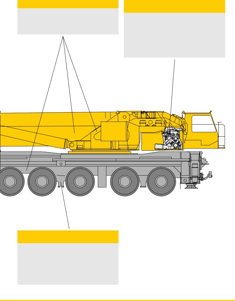
Weight-optimized steel structure
•Carrier, superstructure and telescopic boom in light-gauge design, calculated by the F.E.M. method, weight-optimized and of particular torsional rigidity
•Tensile property of material with high safety factors through the application of STE 960 (960 N/mm2) for all supporting members
Crane drive with proved components
•6-cylinder Liebherr turbo-charged Diesel engine type D936L A6 of 240 kW/326 h.p, exhaust gas emissions in accordance with the directives 97/68/EG stage 3 and EPA/CARB Tier 3, electronically controlled engine speed, engine located laterally to the rear of the superstructure
•Pump distribution gear with 4 servo-controlled axial piston variable displacement pumps operating in a closed oil circuit for winches 1, 2, 3 and slewing gear; 2 servo-controlled double axial piston variable displacement pumps in an open oil circuit for luffing/telescoping; oil cooler within the hydraulic oil circuit
Crane and road-preserving Niveaumatik suspension
•Maintenance-free suspension rams, free of lateral forces and protected by synthetic tubes
•Level adjustment (suspension set to ”travel mode”) can be performed automatically by push-button control from any position
•Stable cornering ability due to cross mounting of the hydraulic suspension
•Axle locking system (locking of the suspension for travelling with equipment) integrated into the suspension ram and controllable from the driver’s cabin
LTM 1500-8.1 |
5 |

Dismantling of telescopes 2 - 6 or 3 - 6 respectively over the vehicle’s rear, front or side
Variant 1
Crane on outriggers, dismantling over the vehicle’s rear
Minimum counterweight with 2 – 6 telescopes |
30 t |
3 – 6 telescopes |
15 t |
min. 9 – max. 11 m |
Variant 2
Crane on outriggers, dismantling over the vehicle’s front
Minimum counterweight with 2 – 6 telescopes |
30 t |
3 – 6 telescopes |
30 t |
min. 9 – max. 11 m |
Variant 3
Crane on outriggers, dismantling over the side |
|
Minimum counterweight with 2 – 6 telescopes |
30 t |
3 – 6 telescopes |
15 t |
|
|
min. 9 – max. 11 m |
|
|
|
|
|
|
|
|
|
|
|
|
|
|
|
|
|
|
|
|
|
|
|
|
|
|
|
|
|
|
|
|
|
|
|
|
|
|
|
|
|
|
|
|
|
|
|
|
|
|
|
|
|
|
|
|
|
|
|
|
|
|
|
|
|
|
|
|
|
|
|
|
|
|
|
|
|
|
|
|
6 |
|
|
|
|
|
|
|
|
|
|
|
|
|
|
|
LTM 1500-8.1 |
|||
 Loading...