


Technical data
Piling and drilling rig
LRB125XL
Concept and characteristics
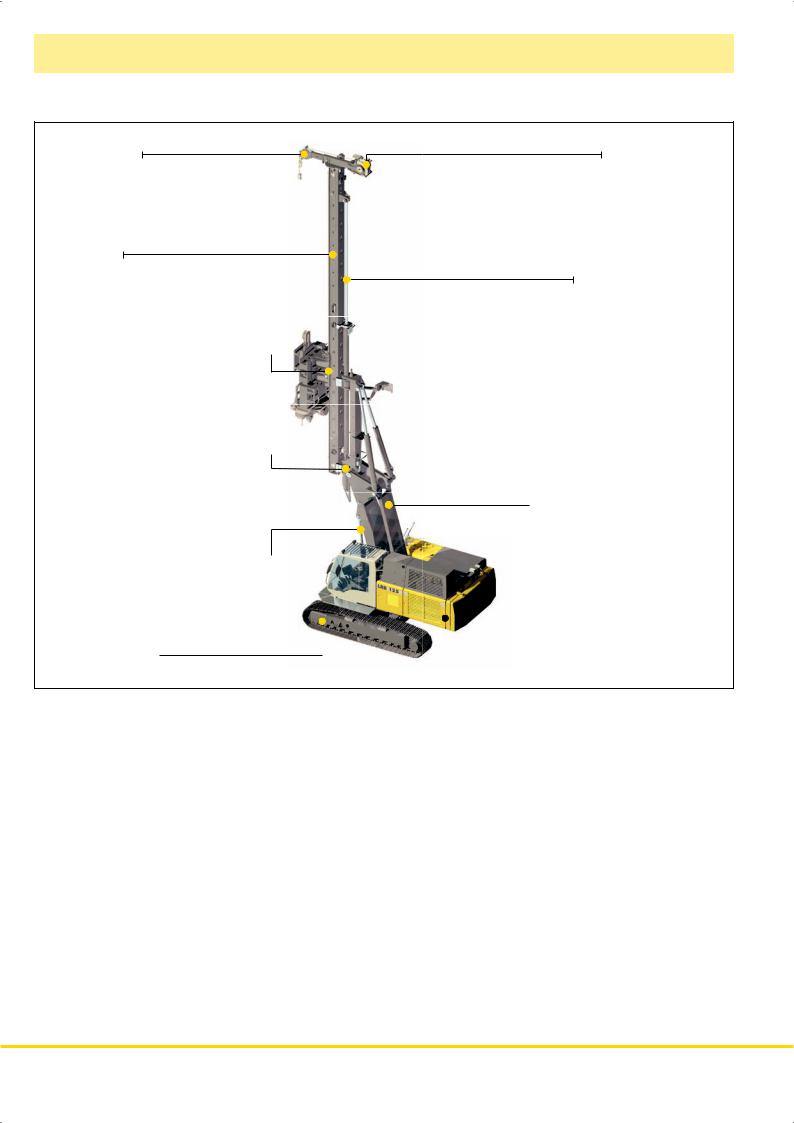
Leader top |
Auxiliary winch |
Leader
Vertical travel device
Tool with quick connection 

 Inclination device
Leader rotation device 

 Parallel kinematics
Radius adjustment device 
Undercarriage |
|
|
|
|
|
Uppercarriage |
|
|
|
|
|
•High engine output with automatic engine speed control
•Controlled entirely from cab
•Sturdy and solid rig design
•Wide longitudinal and lateral supporting system on the basic machine through triangles
•High push and pull forces
•High torque
•Completely self–rigging (no auxiliary machines required)
•Large range of working tools (all piling and drilling works can be performed)
•Stepless leader inclination 1:6 forward – 1:3 backward depending on type of equipment
•Leader swing range ± 90º
•Increase of effective leader length (5 m) via vertical travel device
•Automatic vertical alignment
•High alignment forces
•Simultaneous control of several movements via Load–sensing multi–circuit hydraulics
•Quick change of equipment possible through quick connection
•Equipment design according to latest European regulations and standards
•High manufacturing quality through quality control by PDE–system
2 LRB 125 XL
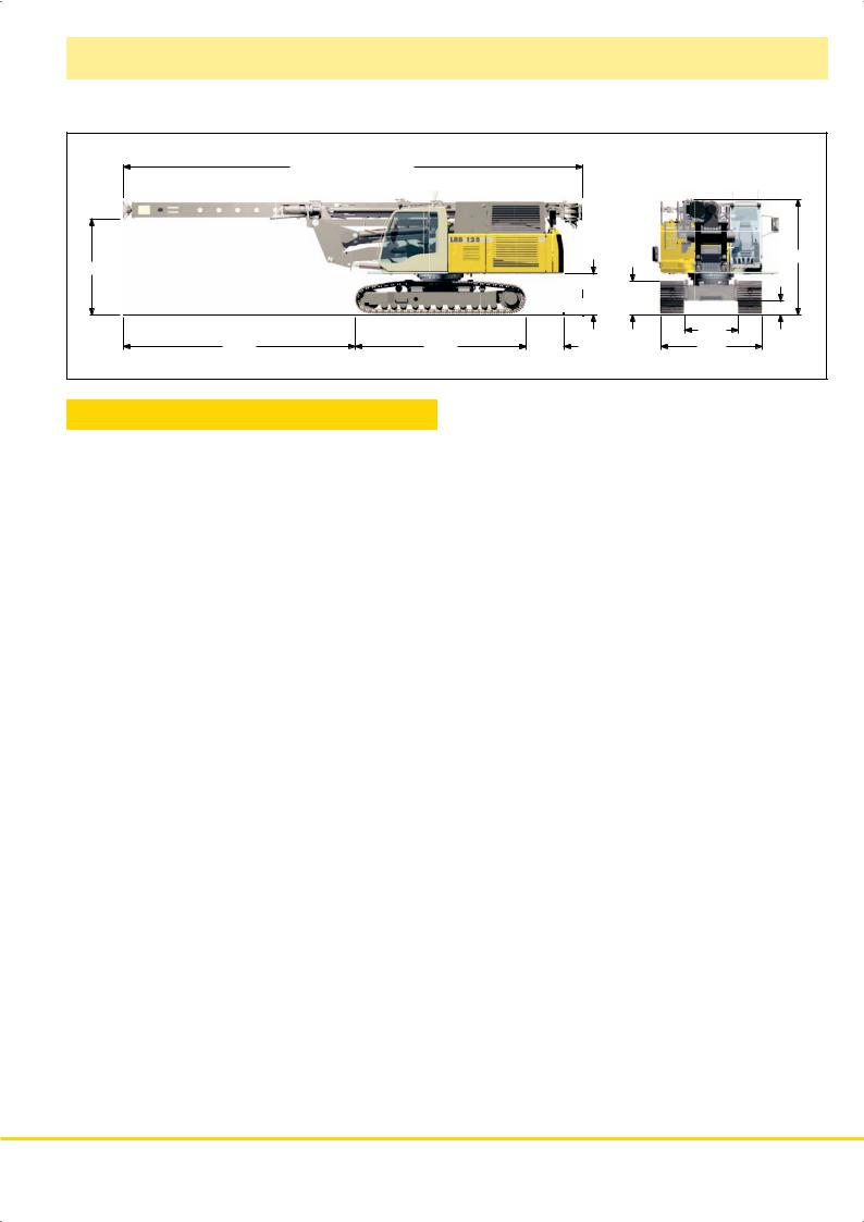
Transport dimensions and weights
|
15850 incl. aux. winch |
|
|
|
|
2850 |
|
|
|
|
3400 |
|
|
|
|
|
|
|
|
|
1180 |
1000 |
|
|
|
|
|
400 |
|
|
|
|
|
|
|
|
|
|
|
|
1600 |
7100 |
5100 |
1120 |
|
|
3000 |
Transport weight*
Without attachment, |
|
|
|
|
with telescopic undercarriage and counterweight |
|
|
46 t |
|
|
|
|||
Without attachment and counterweight, |
|
|
|
|
with telescopic undercarriage |
|
|
40.7 t |
|
|
|
|||
*) Weights can vary with the fi nal confi guration of the machine.
LRB 125 XL 3

Dimensions
Basic machine LRB 125
17500
3300
Technical data
Leader length
Capacity hammer including cap plus pile Max. hammer weight
Max. pile weight Max. pull
Max. torque
Working radius machine Center of rotation — center pile
Stepless rig inclination adjustment Lateral inclination
Forward inclination Backward inclination
Vertical leader adjustment above ground level (depending on radius) Leader swing range
1:6 |
1:3 |
2.8° |
2.8 |
° |
|
||||
|
|
|
||
|
|
|
|
3150 |
3670 |
700 |
|
|
|
5350 |
|
4200 |
|
|
90°
90°
15 m
12 t
6 t
6 t
200 kN
120 kNm
3.15— 5.35 m
±1:20
1:6
1:3
5 m
± 90°
Operating weight and ground pressure
Telescopic undercarriage with |
|
700 mm 3–web shoes |
52 t – 0.88 cm2 |
The operating weight includes the basic machine LRB 125 (leader length 15 m, with attachment). Weights can vary depending on the fi nal confi guration of the machine.
4 LRB 125 XL
 Loading...