


FS-C8020MFP
Table of contents
 Loading...
SERVICE
MANUAL
Published in May 2013
842KZ11B
2KZSM06B
Rev.B
TASKalfa 205c
TASKalfa 255c
FS-C8020MFP
FS-C8025MFP

CAUTION
RISK OF EXPLOSION IF BATTERY IS REPLACED BY AN INCORRECT TYPE. DISPOSE
OF USED BATTERIES ACCORDING TO THE INSTRUCTIONS.
It may be illegal to dispose of this battery into the municipal waste stream. Check with your
local solid waste officials for details in your area for proper disposal.
ATTENTION
IL Y A UN RISQUE D’EXPLOSION SI LA BATTERIE EST REMPLACEE PAR UN MODELE
DE TYPE INCORRECT. METTRE AU REBUT LES BATTERIES UTILISEES SELON LES
INSTRUCTIONS DONNEES.
Il peut être illégal de jeter les batteries dans des eaux d’égout municipales. Vérifiez avec les
fonctionnaires municipaux de votre région pour les détails concernant des déchets solides
et une mise au rebut appropriée.

Revision history
Revision Date Replaced pages Remarks
1 17 January 2011 1-3-1, 1-3-2, 1-3-14, 1-3-52, 1-3-92 -
2 1 March 2011 Safety recautions, 1-1-1, 1-1-2, 1-1-4, 1-1-5 -
3 7 April 2011 CONTENTS, 1-2-13, 1-3-2, 1-3-6, 1-3-7, 1-3-22,
1-3-28, 1-3-29, 1-3-53, 1-3-89 to 1-3-115, 1-3-134,
1-3-137, 1-4-10, 1-4-11
-
4 1 July 2011 CONTENTS, 1-3-2 to 1-3-8, 1-3-22, 1-3-33, 1-3-52,
1-3-53, 1-3-59 to 61, 1-3-70, 1-3-85, 1-3-87, 1-3-88,
1-4-4, 1-4-22 to 1-4-26, 1-4-28, 1-5-22, 1-5-23,
Address
-
5 7 November 2011 CONTENTS, 1-3-2 to 1-3-9, 1-3-43, 1-3-79, 1-3-80,
1-3-123,1-5-31, 1-6-1 to 1-6-4
-
6 21 June 2012 Contents, 1-3-6, 1-3-15, 1-3-93, 1-3-94, 1-4-35,
1-5-15, Address
-
7 19 July 2012 1-3-4, 1-3-15, 1-3-16, 1-3-45, 1-3-46, 1-3-59, 2-4-1 -
8 20 August 2012 1-3-80, 1-3-143, 1-3-144, 2-4-11 -
9 1 December 2012 Contents, 1-3-2, 1-3-3, 1-3-29, 1-3-44 to 1-3-52,
1-6-2, 2-4-8, 2-4-10, 2-4-11
-
A 12 Febraury 2013 Contents, 1-3-83, 1-5-20 to 23, Address -
B 27 May 2013 Contents, 1-4-8, 1-4-27, 1-4-28, 1-4-47 to 51,
2-2-6, 2-2-7, 2-4-12
-

This page is intentionally left blank.

Safety precautions
This booklet provides safety warnings and precautions for our service personnel to ensure the safety of
their customers, their machines as well as themselves during maintenance activities. Service personnel
are advised to read this booklet carefully to familiarize themselves with the warnings and precautions
described here before engaging in maintenance activities.
Safety warnings and precautions
Various symbols are used to protect our service personnel and customers from physical danger and
to prevent damage to their property. These symbols are described below:
DANGER: High risk of serious bodily injury or death may result from insufficient attention to or incorrect
compliance with warning messages using this symbol.
WARNING: Serious bodily injury or death may result from insufficient attention to or incorrect compliance
with warning messages using this symbol.
CAUTION: Bodily injury or damage to property may result from insufficient attention to or incorrect com-
pliance with warning messages using this symbol.
Symbols
The triangle ( ) symbol indicates a warning including danger and caution. The specific point of attention is
shown inside the symbol.
General warning. Warning of risk of electric shock.
Warning of high temperature.
indicates a prohibited action. The specific prohibition is shown inside the symbol.
General prohibited action. Disassembly prohibited.
indicates that action is required. The specific action required is shown inside the symbol.
General action required. Remove the power plug from the wall outlet.
Always ground the copier.

1. Installation Precautions
WARNING
• Do not use a power supply with a voltage other than that specified. Avoid multiple connections to
one outlet: they may cause fire or electric shock. When using an extension cable, always check that
it is adequate for the rated current. .....................................................................................................
• Connect the ground wire to a suitable grounding point. Not grounding the copier may cause fire or
electric shock. Connecting the earth wire to an object not approved for the purpose may cause
explosion or electric shock. Never connect the ground cable to any of the following: gas pipes, light-
ning rods, ground cables for telephone lines and water pipes or faucets not approved by the proper
authorities. ..........................................................................................................................................
CAUTION:
• Do not place the copier on an infirm or angled surface: the copier may tip over, causing injury. .........
• Do not install the copier in a humid or dusty place. This may cause fire or electric shock. .................
• Do not install the copier near a radiator, heater, other heat source or near flammable material. This
may cause fire. ...................................................................................................................................
• Allow sufficient space around the copier to allow the ventilation grills to keep the machine as cool
as possible. Insufficient ventilation may cause heat buildup and poor copying performance. ............
• Always handle the machine by the correct locations when moving it. .................................................
• Always use anti-toppling and locking devices on copiers so equipped. Failure to do this may cause
the copier to move unexpectedly or topple, leading to injury. ..............................................................
• Avoid inhaling toner or developer excessively. Protect the eyes. If toner or developer is accidentally
ingested, drink a lot of water to dilute it in the stomach and obtain medical attention immediately.
If it gets into the eyes, rinse immediately with copious amounts of water and obtain medical atten-
tion. .....................................................................................................................................................
• Advice customers that they must always follow the safety warnings and precautions in the copier’s
instruction handbook. .........................................................................................................................
2. Precautions for Maintenance
WARNING
• Always remove the power plug from the wall outlet before starting machine disassembly. ................
• Always follow the procedures for maintenance described in the service manual and other related
brochures. ..........................................................................................................................................
• Under no circumstances attempt to bypass or disable safety features including safety mechanisms
and protective circuits. ........................................................................................................................
• Always use parts having the correct specifications. ............................................................................
• Always use the thermostat or thermal fuse specified in the service manual or other related brochure
when replacing them. Using a piece of wire, for example, could lead to fire or other serious acci-
dent. ...................................................................................................................................................
• When the service manual or other serious brochure specifies a distance or gap for installation of a
part, always use the correct scale and measure carefully. ..................................................................
• Always check that the copier is correctly connected to an outlet with a ground connection. ...............
• Check that the power cable covering is free of damage. Check that the power plug is dust-free. If it
is dirty, clean it to remove the risk of fire or electric shock. .................................................................
• Never attempt to disassemble the optical unit in machines using lasers. Leaking laser light may
damage eyesight. ...............................................................................................................................
• Handle the charger sections with care. They are charged to high potentials and may cause electric
shock if handled improperly. ...............................................................................................................
CAUTION
• Wear safe clothing. If wearing loose clothing or accessories such as ties, make sure they are safely
secured so they will not be caught in rotating sections. ......................................................................
• Use utmost caution when working on a powered machine. Keep away from chains and belts. ..........
• Handle the fixing section with care to avoid burns as it can be extremely hot. ..................................
• Check that the fixing unit thermistor, heat and press rollers are clean. Dirt on them can cause
abnormally high temperatures. ...........................................................................................................

• Do not remove the ozone filter, if any, from the copier except for routine replacement. ......................
• Do not pull on the AC power cord or connector wires on high-voltage components when removing
them; always hold the plug itself. ........................................................................................................
• Do not route the power cable where it may be stood on or trapped. If necessary, protect it with a
cable cover or other appropriate item. ................................................................................................
• Treat the ends of the wire carefully when installing a new charger wire to avoid electric leaks. ..........
• Remove toner completely from electronic components. .....................................................................
• Run wire harnesses carefully so that wires will not be trapped or damaged. ......................................
• After maintenance, always check that all the parts, screws, connectors and wires that were
removed, have been refitted correctly. Special attention should be paid to any forgotten connector,
trapped wire and missing screws. .......................................................................................................
• Check that all the caution labels that should be present on the machine according to the instruction
handbook are clean and not peeling. Replace with new ones if necessary. .......................................
• Handle greases and solvents with care by following the instructions below: ......................................
· Use only a small amount of solvent at a time, being careful not to spill. Wipe spills off completely.
· Ventilate the room well while using grease or solvents.
· Allow applied solvents to evaporate completely before refitting the covers or turning the power
switch on.
· Always wash hands afterwards.
• Never dispose of toner or toner bottles in fire. Toner may cause sparks when exposed directly to
fire in a furnace, etc. ...........................................................................................................................
• Should smoke be seen coming from the copier, remove the power plug from the wall outlet immedi-
ately. ...................................................................................................................................................
3. Miscellaneous
WARNING
• Never attempt to heat the drum or expose it to any organic solvents such as alcohol, other than the
specified refiner; it may generate toxic gas. ........................................................................................
• Keep the machine away from flammable liquids, gases, and aerosols. A fire or an electric shock
might occur. ........................................................................................................................................

This page is intentionally left blank.

2KZ/2K0-B
CONTENTS
1-1 Specifications
1-1-1 Specifications ........................................................................................................................ 1-1-1
1-1-2 Parts names .......................................................................................................................... 1-1-6
(1) Machine (front side).......................................................................................................... 1-1-6
(2) Machine (rear side)........................................................................................................... 1-1-8
(3) Operation panel ................................................................................................................ 1-1-9
1-1-3 Machine cross section ......................................................................................................... 1-1-10
1-2 Installation
1-2-1 Installation environment......................................................................................................... 1-2-1
1-2-2 Unpacking and installation..................................................................................................... 1-2-2
(1) Installation procedure ....................................................................................................... 1-2-2
(2) Setting initial copy modes............................................................................................... 1-2-13
1-2-3 Install the expansion memory (option)................................................................................. 1-2-14
1-3 Maintenance Mode
1-3-1 Maintenance mode ................................................................................................................ 1-3-1
(1) Executing a maintenance item ......................................................................................... 1-3-1
(2) Maintenance modes item list ............................................................................................ 1-3-2
(3) Contents of the maintenance mode items ...................................................................... 1-3-10
1-3-2 Service mode..................................................................................................................... 1-3-133
(1) Printing the service status page ................................................................................... 1-3-133
(2) Executing a service mode ............................................................................................ 1-3-140
(3) Description of service mode ......................................................................................... 1-3-140
1-4 Troubleshooting
1-4-1 Paper misfeed detection ........................................................................................................ 1-4-1
(1) Paper misfeed indication .................................................................................................. 1-4-1
(2) Paper misfeed detection component ................................................................................ 1-4-2
1-4-2 Self-diagnostic function ......................................................................................................... 1-4-9
(1) Self-diagnostic function .................................................................................................... 1-4-9
(2) Self-diagnostic codes ....................................................................................................... 1-4-9
1-4-3 Image quality problems ....................................................................................................... 1-4-38
(1) No image appears (entirely white).................................................................................. 1-4-39
(2) No image appears (entirely black).................................................................................. 1-4-39
(3) Image is too light. ........................................................................................................... 1-4-40
(4) The background is colored. ............................................................................................ 1-4-40
(5) White streaks are printed vertically................................................................................. 1-4-40
(6) Black streaks are printed vertically. ................................................................................ 1-4-41
(7) Streaks are printed horizontally. ..................................................................................... 1-4-41
(8) One side of the print image is darker than the other. ..................................................... 1-4-41
(9) Spots are printed. ...........................................................................................................1-4-42
(10) Image is blurred.............................................................................................................. 1-4-42
(11) The leading edge of the image is consistently misaligned with the original. ..................1-4-42
(12) The leading edge of the image is sporadically misaligned with the original. ..................1-4-42
(13) Paper is wrinkled. ........................................................................................................... 1-4-43
(14) Image is off-set. .............................................................................................................. 1-4-43
(15) Part of image is missing. ................................................................................................ 1-4-43
(16) Fusing is loose................................................................................................................ 1-4-43
(17) Image is out of focus. ..................................................................................................... 1-4-44

2KZ/2K0-B
(18) Image center does not align with the original center. ..................................................... 1-4-44
1-4-4 Electric problems ................................................................................................................. 1-4-45
1-4-5 Mechanical problems........................................................................................................... 1-4-52
1-4-6 Send error code ................................................................................................................... 1-4-54
(1) Scan to SMB error codes ............................................................................................... 1-4-54
(2) Scan to FTP error codes ................................................................................................ 1-4-55
(3) Scan to E-mail error codes ............................................................................................. 1-4-56
1-5 Assembly and disassembly
1-5-1 Precautions for assembly and disassembly........................................................................... 1-5-1
(1) Precautions....................................................................................................................... 1-5-1
(2) Drum unit .......................................................................................................................... 1-5-1
(3) Toner ................................................................................................................................ 1-5-1
(4) How to tell a genuine Kyocera Mita toner container ......................................................... 1-5-2
1-5-2 Outer covers .......................................................................................................................... 1-5-3
(1) Detaching and refitting the front cover.............................................................................. 1-5-3
(2) Detaching and refitting the rear cover .............................................................................. 1-5-5
(3) Detaching and refitting the inner tray................................................................................ 1-5-6
(4) Detaching and refitting the eject rear cover...................................................................... 1-5-8
1-5-3 Paper feed section............................................................................................................... 1-5-10
(1) Detaching and refitting the primary paper feed unit........................................................ 1-5-10
(2) Detaching and refitting the MP paper feed roller and MP separation pad...................... 1-5-11
(3) Detaching and refitting the registration roller.................................................................. 1-5-12
(4) Detaching and refitting the registration cleaner .............................................................. 1-5-13
(5) Detaching and refitting the MP tray ................................................................................ 1-5-13
1-5-4 Developing section .............................................................................................................. 1-5-14
(1) Detaching and refitting the developing unit .................................................................... 1-5-14
1-5-5 Drum section ....................................................................................................................... 1-5-16
(1) Detaching and refitting the drum unit.............................................................................. 1-5-16
(2) Detaching and refitting the chager roller unit.................................................................. 1-5-16
1-5-6 Transfer/separation section ................................................................................................. 1-5-17
(1) Detaching and refitting the intermediate transfer unit..................................................... 1-5-17
(2) Detaching and refitting the secondary transfer roller unit ............................................... 1-5-17
1-5-7 Fuser section ....................................................................................................................... 1-5-18
(1) Detaching and refitting the fuser unit.............................................................................. 1-5-18
1-5-8 Drive section........................................................................................................................ 1-5-19
(1) Detaching and refitting the conveying motor .................................................................. 1-5-19
(2) Detaching and refitting the drive unit .............................................................................. 1-5-19
1-5-9 Optical section ..................................................................................................................... 1-5-20
(1) Detaching and refitting the laser scanner unit ................................................................ 1-5-20
(2) Checks and adjusts the assembly frame of LSU unit ..................................................... 1-5-21
(3) Color registration adjustment.......................................................................................... 1-5-22
(4) Detaching and refitting the image scanner unit .............................................................. 1-5-24
(5) Detaching and refitting the LED unit............................................................................... 1-5-27
1-5-10 Document processor ........................................................................................................... 1-5-29
(1) Detaching and refitting the document processor ............................................................ 1-5-29
(2) Detaching and refitting the DP paper feed roller and DP separation pulley ................... 1-5-30
(3) Detaching and refitting the DP main PWB...................................................................... 1-5-32
1-5-11 PWBs................................................................................................................................... 1-5-34
(1) Detaching and refitting the main PWB............................................................................ 1-5-34
(2) Detaching and refitting the engine PWB......................................................................... 1-5-35
(3) Detaching and refitting the power source PWB.............................................................. 1-5-36
(4) Detaching and refitting the operation panel PWB main.................................................. 1-5-37

2KZ/2K0-A
(5) Detaching and refitting the IH PWB................................................................................ 1-5-39
1-5-12 Others .................................................................................................................................. 1-5-40
(1) Detaching and refitting the language sheet .................................................................... 1-5-40
(2) Detaching and refitting the conveying unit...................................................................... 1-5-41
(3) Detaching and refitting the imaging fan motor................................................................ 1-5-43
(4) Direction of installing the principal fan motors ................................................................ 1-5-43
1-6 Requirements on PWB Replacement
1-6-1 Upgrading the firmware ......................................................................................................... 1-6-1
1-6-2 Remarks on PWB replacement ............................................................................................. 1-6-3
(1) Engine PWB ..................................................................................................................... 1-6-3
(2) DP main PWB................................................................................................................... 1-6-3
(3) Main PWB......................................................................................................................... 1-6-4
2-1 Mechanical Construction
2-1-1 Paper feed/conveying section ............................................................................................... 2-1-1
(1) Cassette paper feed section............................................................................................. 2-1-1
(2) MP tray paper feed section............................................................................................... 2-1-3
(3) Conveying section ............................................................................................................2-1-4
2-1-2 Drum section ......................................................................................................................... 2-1-5
2-1-3 Developing section ................................................................................................................ 2-1-7
2-1-4 Optical section ....................................................................................................................... 2-1-9
(1) Image scanner section ..................................................................................................... 2-1-9
(2) Laser scanner section .................................................................................................... 2-1-11
2-1-5 Transfer/Separation section ................................................................................................ 2-1-13
(1) Intermediate transfer unit section ................................................................................... 2-1-13
(2) Secondary transfer roller section.................................................................................... 2-1-15
2-1-6 Fuser section ....................................................................................................................... 2-1-16
2-1-7 Eject/Feedshift section ........................................................................................................ 2-1-18
2-1-8 Duplex conveying section.................................................................................................... 2-1-20
2-1-9 Document processor ........................................................................................................... 2-1-22
(1) Original feed section....................................................................................................... 2-1-22
(2) Original conveying section.............................................................................................. 2-1-24
(3) Original switchback/eject sections .................................................................................. 2-1-26
2-2 Electrical Parts Layout
2-2-1 Electrical parts layout ............................................................................................................ 2-2-1
(1) PWBs................................................................................................................................ 2-2-1
(2) Switches and sensors....................................................................................................... 2-2-4
(3) Motors............................................................................................................................... 2-2-6
(4) Others............................................................................................................................... 2-2-8
2-3 Operation of the PWBs
2-3-1 Main PWB.............................................................................................................................. 2-3-1
2-3-2 Engine PWB .......................................................................................................................... 2-3-7
2-3-3 Power source PWB ............................................................................................................. 2-3-20
2-3-4 IH PWB................................................................................................................................ 2-3-23
2-3-5 Operation panel PWB main ................................................................................................. 2-3-26
2-3-6 DP main PWB...................................................................................................................... 2-3-31

2KZ/2K0-A
2-4 Appendixes
2-4-1 Appendixes ............................................................................................................................ 2-4-1
(1) Maintenance kits............................................................................................................... 2-4-1
(2) Repetitive defects gauge .................................................................................................. 2-4-2
(3) Firmware environment commands ................................................................................... 2-4-3
(4) Chart of image adjustment procedures .......................................................................... 2-4-10
(5) Wiring diagram ............................................................................................................... 2-4-12
Installation Guide
Paper feeder
Document finisher
FAX System(U)

2KZ/2K0-2
1-1-1
1-1 Specifications
1-1-1 Specifications
Machine
Item
Specifications
20ppm 25ppm
Type Desktop
Printing method Electrophotography by semiconductor laser, tandem (4) drum system
Originals Sheet, Book, 3-dimensional objects (maximum original size: A3/Ledger)
Original feed system Fixed
Paper weight
Cassette 60 to 256 g/m
2
(Duplex: 60 to 220 g/m
2
)
MP tray 60 to 256 g/m
2
, 230μm (Cardstock)
Paper type
Cassette
Plain, Recycled, Preprinted, Bond, Color (Colour), Letterhead, Thick,
High quality, Custom 1 to 8 (Duplex: Same as simplex)
MP tray
Plain, Vellum, Recycled, Preprinted, Bond, Cardstock, Color (Colour),
Letterhead, Thick, Envelope, Coated, High quality, Custom 1 to 8
Paper size
Cassette
A3, A4, A5, A6, B5, Ledger, Letter, Legal, Statement, Executive, Oficio II,
Folio, 16K,Envelope C5, Custom
MP tray
A3, A4, A5, A6, B5, ISO B5, B6, Ledger, Letter, Legal, Statement,
Executive, Oficio II, Folio, 16K, Envelope #10, Envelope #9, Envelope #6,
Envelope Monarch, Envelope DL, Envelope C5, Postcards,
Return postcard, Youkei 2, Youkei 4, Custom
Zoom level
Manual mode : (When using the DP) 25 to 400%, 1% increments
(When the DP is not used) 25 to 400%, 1% increments
Auto mode : 400%, 200%, 141%, 122%, 115%, 86%, 81%, 70%, 50%,
25%
Copying
speed
(Simplex)
Color B/W Color B/W
A4/Letter 20 sheets/min 20 sheets/min 25 sheets/min 25 sheets/min
A4R/LetterR 14 sheets/min 14 sheets/min 17 sheets/min 17 sheets/min
A3/Ledger 8 sheets/min 10 sheets/min 9 sheets/min 13 sheets/min
B4/Legal 9 sheets/min 10 sheets/min 10 sheets/min 13 sheets/min
B5 20 sheets/min 20 sheets/min 25 sheets/min 25 sheets/min
B5R 14 sheets/min 14 sheets/min 17 sheets/min 17 sheets/min
A5R 10 sheets/min 10 sheets/min 13 sheets/min 13 sheets/min
First copy time
(A4, feed from cassette)
B/W : 11.7 s or less
Color : 13.6 s or less
Warm-up time
(22 °C/71.6 °F, 60% RH)
Power on : 55 s or less Power on : 45 s or less
Paper
capacity
Cassette 500 sheets (80g/m
2
)
MP tray
100 sheets (80 g/m
2
, plain paper, A4/Letter or less)
25 sheets (80 g/m
2
, plain paper, A4/Letter or more)
Output tray capacity
Inner tray : 250 sheets (80g/m
2
)
Job separator : 150 sheets (80g/m
2
)

2KZ/2K0-2
1-1-2
Continuous copying 1 to 999 sheets
Light source White LED
Scanning system Flat bed scanning by CCD image sensor
Photoconductor OPC drum (diameter 30 mm)
Image write system Semiconductor laser:
Charging system Contact charger roller method
Developer system
Touch down developing system
Developer: 2-component
Toner replenishing: Automatic from the toner container
Transfer system
Primary: Transfer belt
Secondary: Transfer roller
Separation system Small diameter separation, separation electrode
Cleaning system Counter blade cleaning
Charge erasing system Exposure by cleaning lamp (LED)
Fusing system
One axis IH established method
Heat source: IH inverter heating
Abnormally high temperature protection devices: thermostat
CPU PowerPC464 (800MHz)
Main
memory
Standard 1024 MB
Maximum 2048 MB
Interface
Standard
USB interface connector: 1 (USB Hi-speed)
USB host: 2 (USB Hi-speed)
Network interface: 1 (10BASE-T/100/1000BASE-TX)
Option
eKUIO slot: 2
Resolution 600 × 600 dpi
Operating
environment
Temperature 10 to 32.5 °C/50 to 90.5 °F
Humidity 15 to 80% RH
Altitude 2,500 m/8,202 ft or less
Brightness 1,500 lux or less
Dimensions (W × D × H) 590 × 590 × 748 mm / 23 1/4” × 23 1/4 “× 29 7/16”
Weight 80 kg / 176.4 lb (with toner containers)
Space required (W × D) 874× 590 mm / 34 7/16” × 23 1/4” (using MP tray)
Power source
120 V AC, 60 Hz, more than 12.0 A
220 - 240 V AC, 50/60 Hz, more than 7.2 A
Options
Paper feeder (single cassette), Paper feeder (double cassette), Document
finisher, Network kit, Fax kit, Expanded memory, Card Authentication KIT
Item
Specifications
20ppm 25ppm

2KZ/2K0
1-1-3
Document processor
Item Specifications
Original feed method Automatic feed
Supported original types Sheet originals
Original sizes
Maximum: A3/Ledger
Minimum : A5/Statement
Original weights
Simplex: 45 to 160 g/m
2
Duplex : 50 to 120 g/m
2
Loading capacity 50 sheets (50 to 80 g/m
2
) or less
Dimensions (W × D × H) 590 × 489 × 123 mm / 23 1/4” × 19 1/4” × 4 13/16”
Weight 7 kg / 15.4 lb or less

2KZ/2K0-2
1-1-4
Printer
Item
Specifications
20ppm 25ppm
Printing
speed
(Simplex)
Color B/W Color B/W
A4/Letter 20 sheets/min 20 sheets/min 25 sheets/min 25 sheets/min
A4R/LetterR 14 sheets/min 14 sheets/min 17 sheets/min 17 sheets/min
A3/Ledger 10 sheets/min 10 sheets/min 13 sheets/min 13 sheets/min
B4/Legal 10 sheets/min 10 sheets/min 13 sheets/min 13 sheets/min
B5 20 sheets/min 20 sheets/min 25 sheets/min 25 sheets/min
B5R 14 sheets/min 14 sheets/min 17 sheets/min 17 sheets/min
A5R 10 sheets/min 10 sheets/min 13 sheets/min 13 sheets/min
Printing
speed
(Duplex)
Color B/W Color B/W
A4/Letter 19 sheets/min 19 sheets/min 23 sheets/min 23 sheets/min
A4R/LetterR 7 sheets/min 7 sheets/min 9 sheets/min 9 sheets/min
A3/Ledger 6 sheets/min 6 sheets/min 7 sheets/min 7 sheets/min
B4/Legal 6sheets/min 6sheets/min 7 sheets/min 7 sheets/min
B5 19 sheets/min 19 sheets/min 23 sheets/min 23 sheets/min
B5R 7 sheets/min 7 sheets/min 9sheets/min 9sheets/min
A5R 10 sheets/min 10 sheets/min 13 sheets/min 13 sheets/min
First print time
(A4, feed from cassette)
B/W : 11.0 s or less
Color : 14.0 s or less
B/W : 10.0 s or less
Color : 12.0 s or less
Resolution 600 × 600 dpi
Operating system
Windows 2000, Windows XP, Windows XP Professional,
Windows Server 2003, Windows Server 2003 x64 Edition,
Windows Vista x86 Edition, Windows Vista x64 Edition,
Windows 7 x86 Edition, Windows 7 x64 Edition, Windows Server 2008,
Windows Server 2008 x64 Edition, Apple Macintosh OS 10.x
Interface
USB interface connector: 1 (USB Hi-speed)
Network interface: 1 (10BASE-T/100/1000BASE-TX)
Page description language PRESCRIBE

2KZ/2K0-2
1-1-5
Scanner
*1 Available operating system: Windows 2000 (Service Pack 2), Windows XP, Windows Vista,
Windows Server 2008, Windows 7
*2 Available operating system: Windows Vista, Windows Server 2008, Windows 7
NOTE: These specifications are subject to change without notice.
Item Specifications
Operating system
Windows 2000 (Service Pack 2), Windows XP, Windows Vista,
Windows 7, Windows Server 2003, Windows Server 2008
System requirements
IBM PC/AT compatible
CPU: Celeron 600 MHz or higher
RAM: 128 MB or more
HDD free space: 20 MB or more
Interface: Ethernet
Resolution 600 dpi, 400 dpi, 300 dpi, 200 dpi, 200 × 100dpi, 200 × 400dpi
File format JPEG, TIFF, PDF, XPS
Scanning
speed
Simplex
B/W : 40 images/min
Color: 40 images/min
(A4 landscape,300 dpi, Image quality: Text/Photo original)
Duplex
B/W : 14 images/min
Color : 14 images/min
(A4 landscape, 300 dpi, Image quality: Text/Photo original)
Interface Ethernet (10 BASE-T/100 BASE-TX)
Network protocol TCP/IP
Transmission system
PC transmission
SMB Scan to SMB
FTP Scan to FTP, FTP over SSL
E-mail transmission
SNTP Scan to E-mail
TWAIN scan*
1
WIA scan*
2
2KZ/2K0
1-1-6
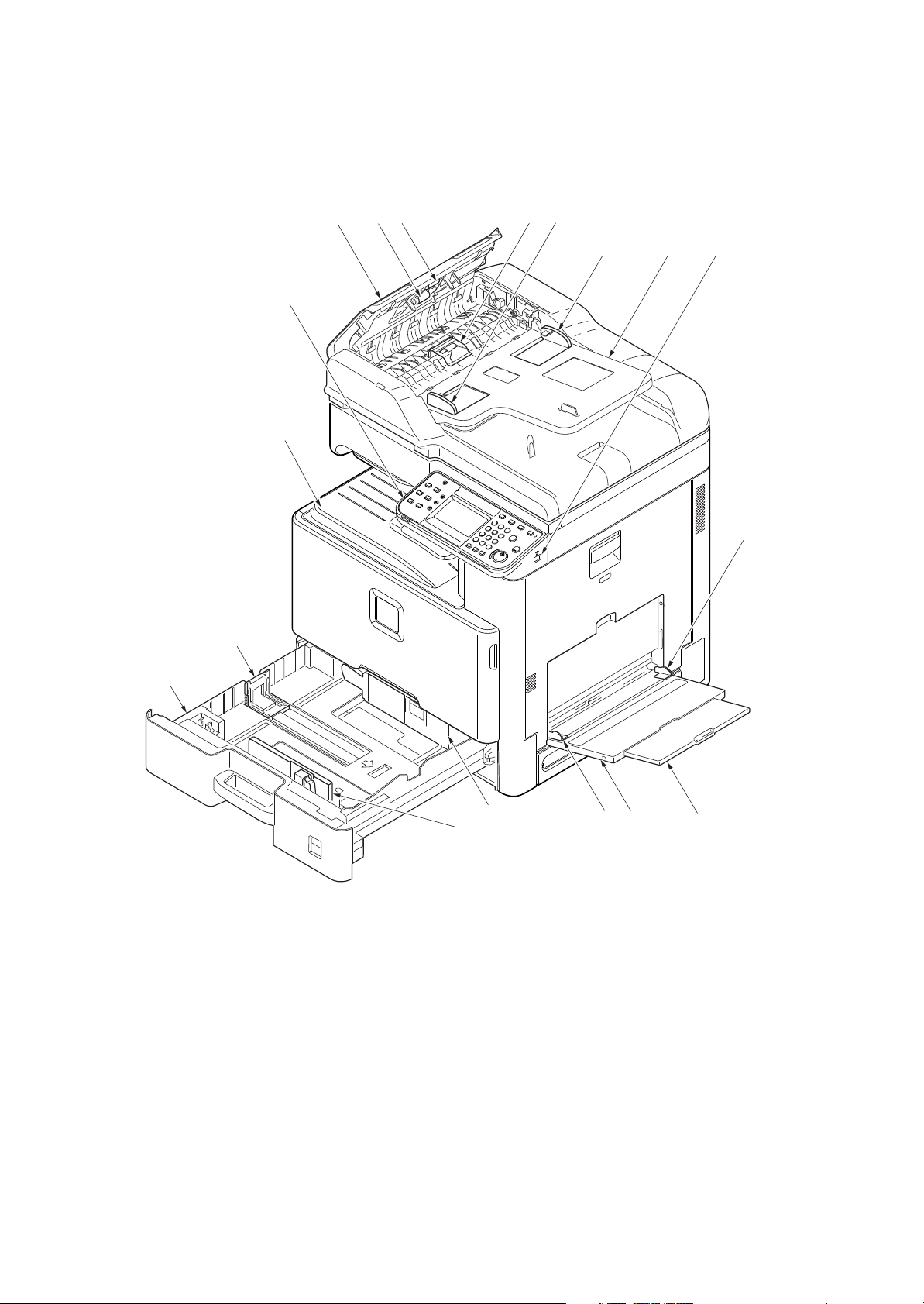
1-1-2 Parts names
(1) Machine (front side)
Figure 1-1-1
7
1
3
2
2
8
11
13
12
10
13
14
4
5
9
6
6
15
1. Cassette
2. Paper width guides
3. Paper length guide
4. MP (multi purpose) tray
5. MP tray extension
6. MP Paper width guides
7. Inner tray
8. Operation panel
9. DP top cover
10. DP paper feed roller
11. DP forwarding roller
12. DP separation pully
13. DP original width guides
14. Original table
15. USB memory slot
2KZ/2K0
1-1-7
Figure 1-1-2
24
18
16
19
21
22
23
20
37
25 26 27 28
33 34 35 36
29 30 31 32
17
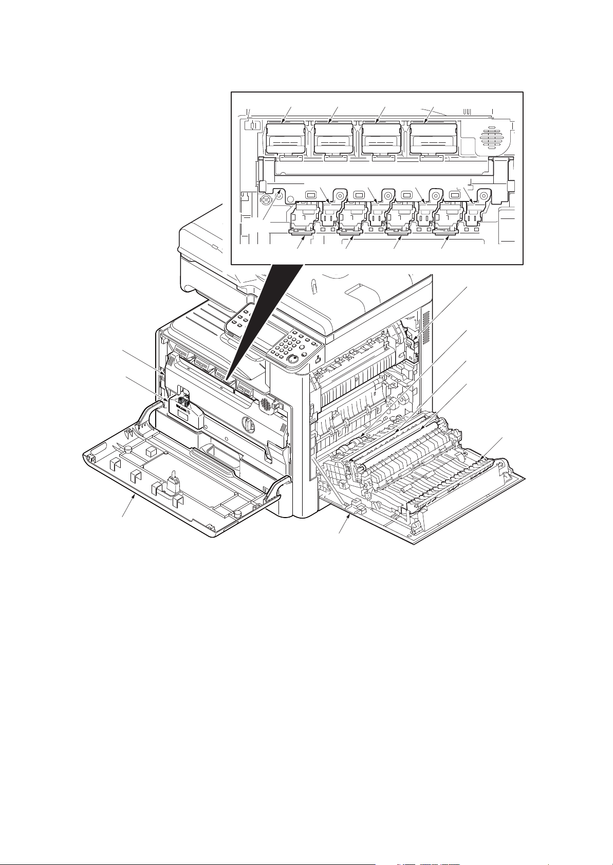
16. Front cover
17. Duct cover
18. Waste toner box
19. Right cover 1
20. MP paper feed roller
21. Right registration roller
22. Secondary transfer roller
23. Feed shift guide
24. Fuser unit
25. Toner container /Y
26. Toner container /C
27. Toner container /M
28. Toner container /K
29. Drum unit /Y
30. Drum unit /C
31. Drum unit /M
32. Drum unit /K
33. Developer unit /Y
34. Developer unit /C
35. Developer unit /M
36. Developer unit /K
37. Duct holder
2KZ/2K0
1-1-8
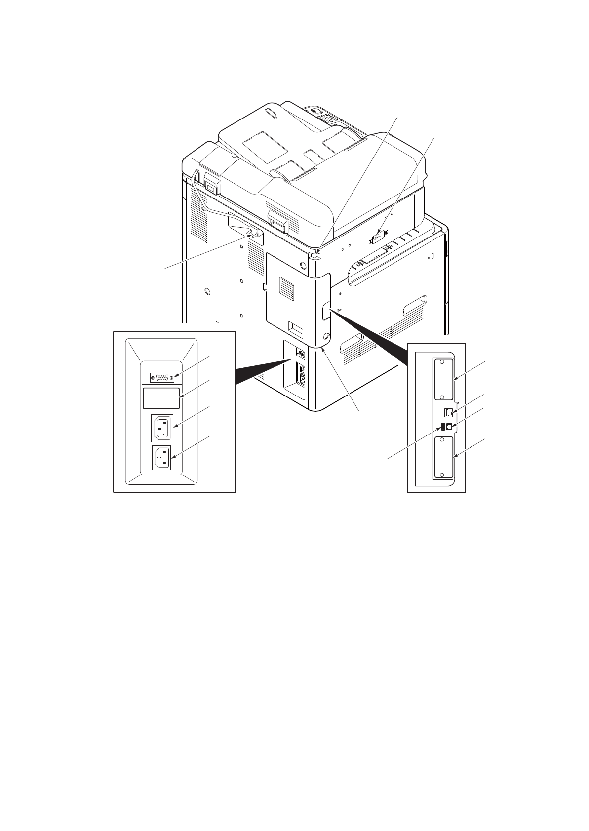
(2) Machine (rear side)
Figure 1-1-3
38
39
43
44
45
47
48
50
46
49
40
41
42
38. Main power switch
39. Scanner lock lever
40. DP interface connector
41. Controller box cover
42. DF interface connector
43. Cassette heater switch (cover)
44. Outlet connector
45. Inlet connector
46. Option interface slot 1
47. Network interface connector
48. USB port
49. USB interface connector
50. Option interface slot 2
2KZ/2K0
1-1-9
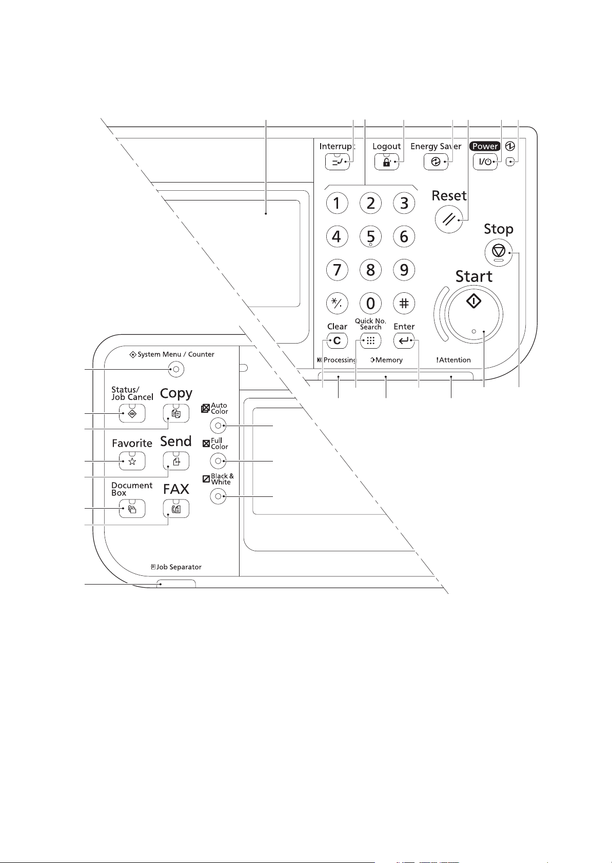
(3) Operation panel
Figure 1-1-4
12
2 4 5 86
13
7
9 10 11
3
17
19
21
15
14
18
20
16
22
23
24
1
25 26 27
1. Message display
2. Interrupt key / LED
3. Numeric keys
4. Logout key / LED
5. Energy saver / LED
6. Reset key
7. Power key / LED
8. Main power LED
9. Clear key
10. Quick No.search key
11. Enter key
12. Start key / LED
13. Stop key
14. System menu/Counter key
/ LED
15. Status/Job cancel / LED
16. Copy key / LED
17. Favorite key / LED
18. Send key / LED
19. Document box key / LED
20. FAX key / LED
21. Job separator LED
22. Auto color key / LED
23. Full color key / LED
24. Black & white key / LED
25. Processing LED
26. Memory LED
27. Attention LED
2KZ/2K0
1-1-10
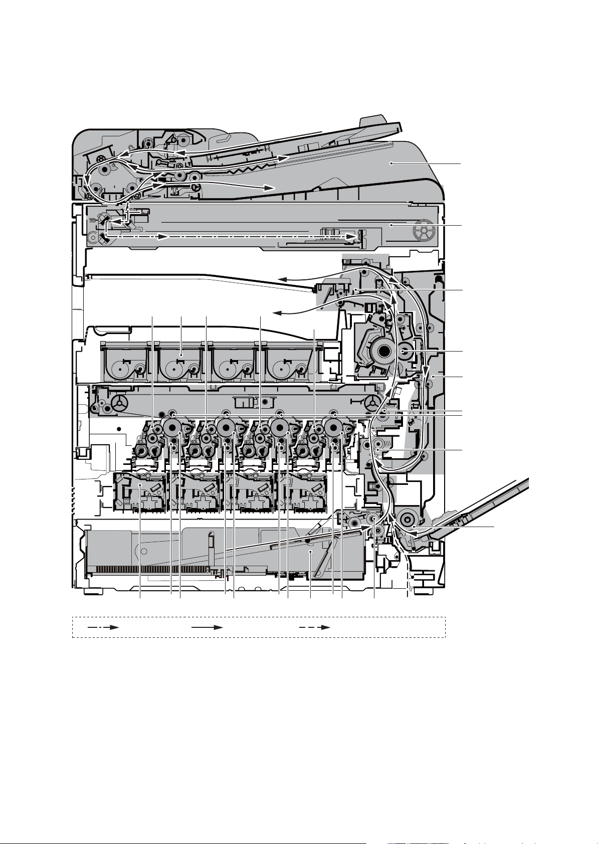
1-1-3 Machine cross section
Figure 1-1-5
Light path Paper path Paper path (option)
3
4
6
5
7
10
22
9
8
1213 14 15
16
1
11
21
11 11 11
17 18 19 20
2
1. Cassette
2. Cassette paper feed section
3. MP tray paper feed section
4. Conveying section
5. Primary transfer section
6. Secondary transfer section /
Separation sections
7. Fuser unit
8. Eject section
9. Duplex/conveyning section
10. Image scanner unit (ISU)
11. Charger roller unit
12. Toner container /YCMK
13. Developer unit /Y
14. Developer unit /C
15. Developer unit /M
16. Developer unit /K
17. Drum unit /Y
18. Drum unit /C
19. Drum unit /M
20. Drum unit /K
21. Laser scanner unit (LSU)
/YCMK
22. Document processor (DP)
2KZ/2K0
1-2-1
1-2 Installation
1-2-1 Installation environment
1. Temperature: 10 to 32.5°C/50 to 90.5°F
2. Humidity: 15 to 80% RH
3. Power supply: 120 V AC, 12.0 A
220 - 240 V AC, 6.5 A
4. Power supply frequency: 50 Hz ±2%/60 Hz ±2%
5. Installation location
Avoid direct sunlight or bright lighting. Ensure that the photoconductor will not be exposed to direct sun-
light or other strong light when removing paper jams.
Avoid locations subject to high temperature and high humidity or low temperature and low humidity; an
abrupt change in the environmental temperature; and cool or hot, direct air.
Avoid places subject to dust and vibrations.
Choose a surface capable of supporting the weight of the machine.
Place the machine on a level surface (maximum allowance inclination: 1°).
Avoid air-borne substances that may adversely affect the machine or degrade the photoconductor, such
as mercury, acidic of alkaline vapors, inorganic gasses, NOx, SOx gases and chlorine-based organic sol-
vents.
Select a well-ventilated location.
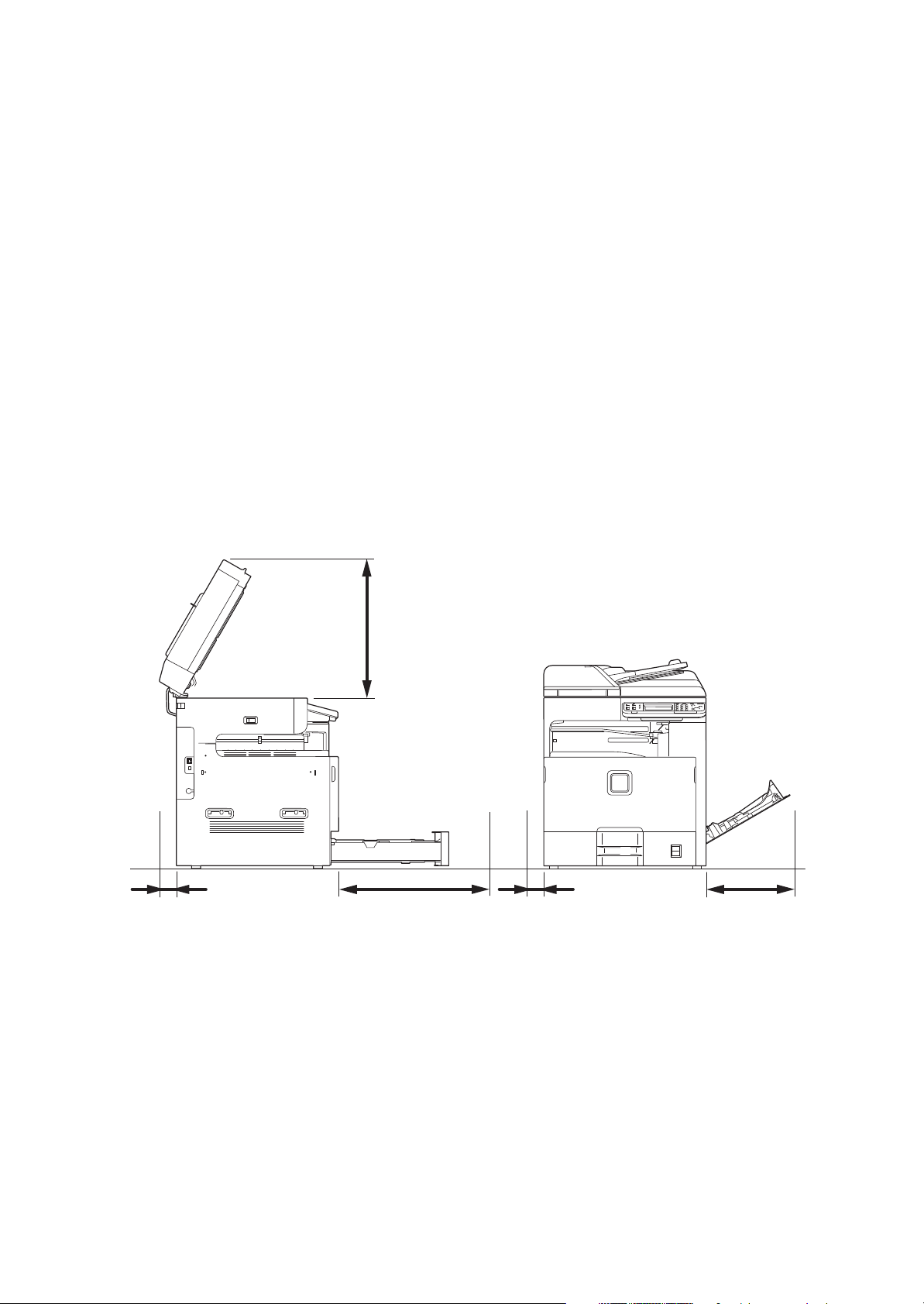
6. Allow sufficient access for proper operation and maintenance of the machine.
Figure 1-2-1
100 mm
3 15/16”
100 mm
3 15/16”
450 mm
17 11/16”
1000 mm
39 3/8”
500 mm
19 11/16”
2KZ/2K0
1-2-2
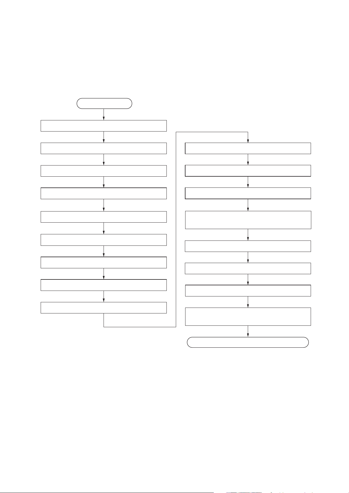
Unpack
Install the optional paper feeder
Release the scanner lock lever
Load paper
Remove the tapes and spacer
Start
Install the toner container
Attaching the language label
(Excluding 240V AC)
Make test copies
Switch the cassette heater switch
Install the expansion memory (option)
Connect the power cord
Exit maintenance mode
Print out the user setting list
Install the other optional devices
Installing toner
Output an own-status report
(maintenance item U000)
Completion of the machine installation
Install the job separator tray
1-2-2 Unpacking and installation
(1) Installation procedure
2KZ/2K0
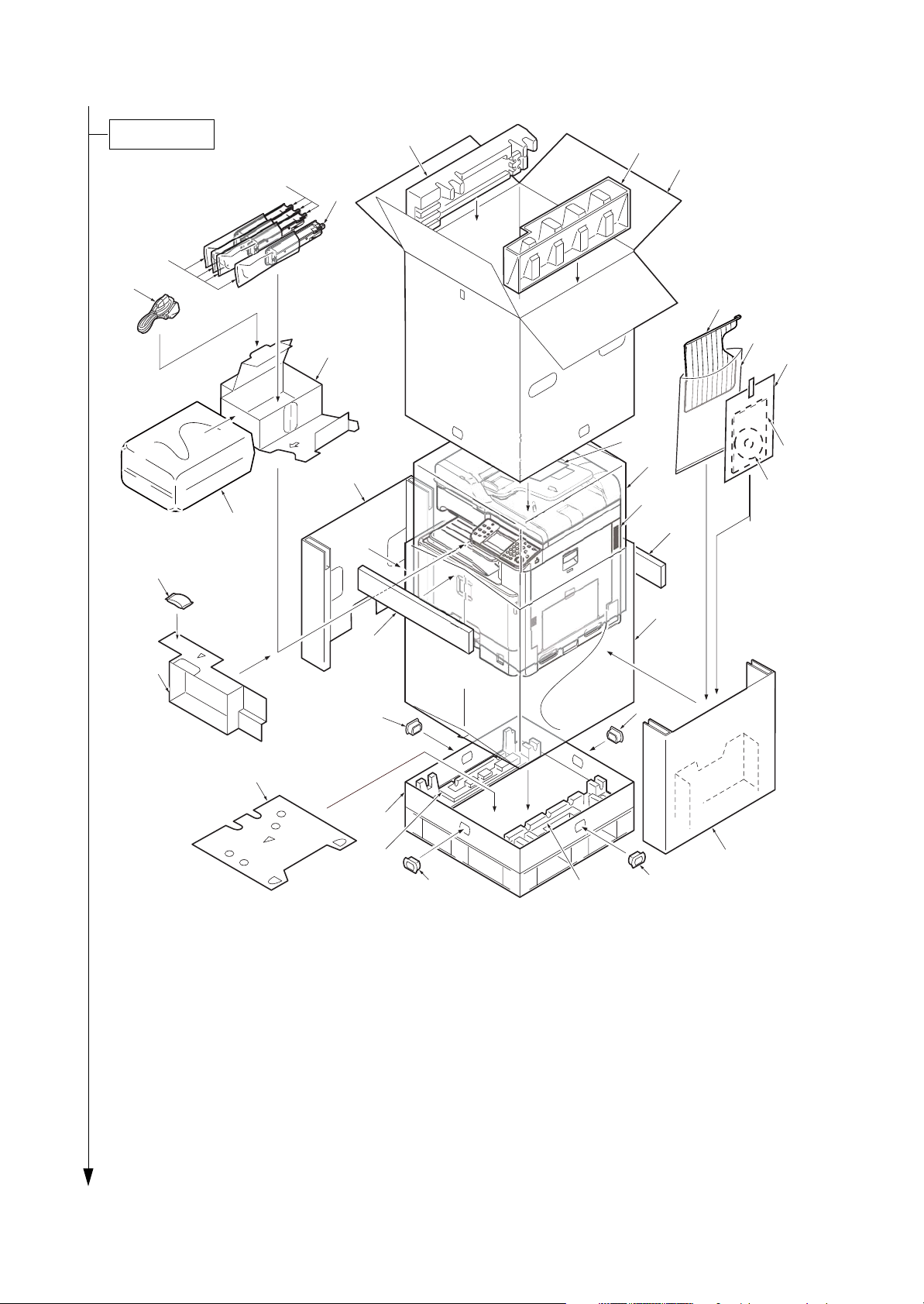
1-2-3
l
Figure 1-2-2
*1 Excluding 230V AC model
Place the machine on a level surface.
1
22
24
2
3
4
5
24
6
7
8
9
10
11
12
22
22
22
21
13
14
15
18
19
20
16
17
23
25
26
27
28
Unpacking
1. Bottom case
2. Bottom pad R
3. Bottom pad L
4. Machine cover
5. Machine
6. Inner case R
7. Inner case L
8. Spacer A
9. Plastic bag (540 × 950)
10. Outer case
11. Upper pad R
12. Upper pad L
13. Toner container /YCM
14. Toner container /K
15. Plastic bag (250 × 650)
16. CD-ROM *
1
17. Installation guide, etc.
18. Plastic bag
19. Job separator tray
20. Plastic bag (400 × 600)
21. Power cord
22. Hinge joints
23. Quick installation guide
24. Reinforcement parts
25. Plastic bag
26. Lower pad
27. Front pad
28. Desiccant

2KZ/2K0
1-2-4
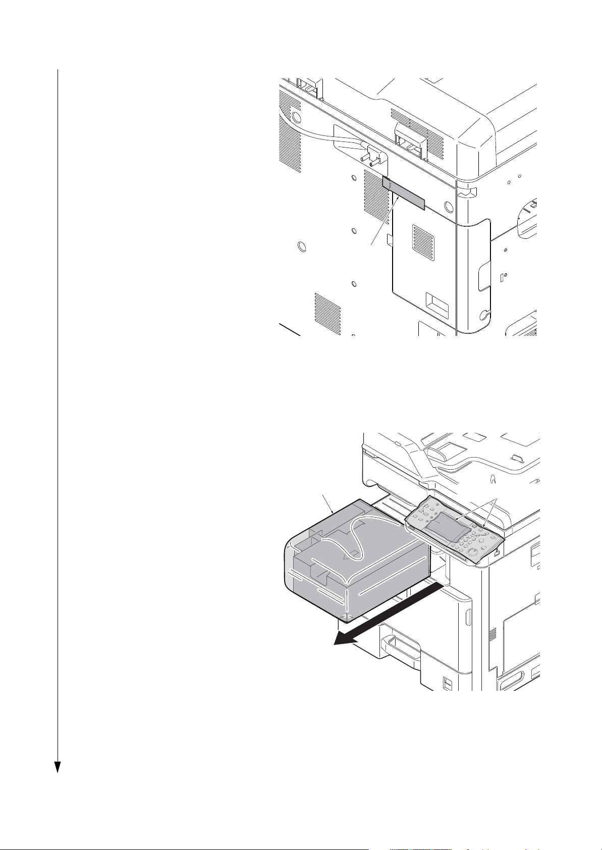
1. Remove four tapes.
Figure 1-2-3
2. Open the DP top cover.
3. Slide two DP original width guides and
then remove the pad.
4. Close the DP top cover.
Figure 1-2-4
Remove the tapes and spacer
Tape
Tape
Tape
Tape
DP top cover
Pad
DP original width guides

2KZ/2K0
1-2-5
5. Open the DP.
6. Remove the protective sheet and paper.
Figure 1-2-5
7. Remove the paper.
8. Close the DP.
Figure 1-2-6
DP
Protective sheet
DP
Paper
2KZ/2K0
1-2-6
9. Remove the tape.
Figure 1-2-7
10. Peel off two protective sheets.
11. Remove the spacer.
Figure 1-2-8
Tape
Spacer
Protective sheets
Loading...