


FS-2100
Table of contents
 Loading...
ECOSYS FS-4300DN
ECOSYS FS-4200DN
ECOSYS FS-4100DN
ECOSYS FS-2100DN
ECOSYS FS-2100D
SERVICE
MANUAL
Published in February 2013
842LV113
2LVSM063
Rev.3

CAUTION
RISK OF EXPLOSION IF BATTERY IS REPLACED BY AN INCORRECT TYPE. DISPOSE
OF USED BATTERIES ACCORDING TO THE INSTRUCTIONS.
It may be illegal to dispose of this battery into the municipal waste stream. Check with your
local solid waste officials for details in your area for proper disposal.
ATTENTION
IL Y A UN RISQUE D’EXPLOSION SI LA BATTERIE EST REMPLACEE PAR UN MODELE
DE TYPE INCORRECT. METTRE AU REBUT LES BATTERIES UTILISEES SELON LES
INSTRUCTIONS DONNEES.
Il peut être illégal de jeter les batteries dans des eaux d’égout municipales. Vérifiez avec les
fonctionnaires municipaux de votre région pour les détails concernant des déchets solides
et une mise au rebut appropriée.
Notation of products in the manual
For the purpose of this service manual, products are identified by print speed at A4.
ECOSYS FS-4300DN : 60 ppm model
ECOSYS FS-4200DN : 50 ppm model
ECOSYS FS-4100DN : 45 ppm model
ECOSYS FS-2100DN : 40 ppm model (with Network)
ECOSYS FS-2100D : 40 ppm model (without Network)

Revision history
Revision Date pages Revised contents
1 11 October 2012
CONTENTS Correction of Page
1-3-1 (3) Printing an event log : 1-3-15 to 1-3-16
Installation guide : SSD(HD-6)
1-1-2 Change of Specification
Output tray capacity / Faceup : 100 sheets to 250 sheets
1-1-3 Change of Description
“Expanded HDD (SSD)” to “SSD (HD-6)”.
1-1-8, 9 Correction of Figure 1-1-6
The position of No.11 was corrected.
1-2-4 Correction of Figure 1-2-6
The container label was changed.
1-2-6 Correction of Figure 1-2-9
1-2-7 Correction of Figure 1-2-13
1-2-8 Correction of Figure 1-2-14 and Figure 1-2-15
1-2-10 Change of Procedures
Procedures 1 and 2 were replaced.
1-3-4, 9 Addition of Description
“(83) Full page printing mode” was added.
1-3-10 Addition of Description
"OP Network Status" was added.
1-3-11 Addition of Description
"Test Page" was added.
1-4-19 Addition of Description
The check of TRA31was added.
1-4-24, 30 Addition of Description
"(15)Carrier leaking occurs." was added.
1-5-9, 10 Change of Procedures
Procedures of "(3) Detaching and refitting the MP paper
feed pulley" was changed.
1-5-31 Correction of Figure 1-5-52
Developer fan motor (Rating label) : outside to inside
2 December 2012 CONTENTS Correction of Page
1-6-2 Remarks on PWB replacement : 1-6-3
1-2-2 Form change of 9, packing position change of 12 and 13
1-3-6 Correction of "description" and "supplement" at (39).
1-3-14 Addition of Service item
“Drum heater (110V only)” was added.
1-6-2 Addition of Procedure
“Emargency-UPDATE” was added.
2-1-8 Addition of the drum heater (110V only).
2-2-7, 8 Addition of the drum heater (110V only).
2-3-6, 9, 10 Addition of the connector of YC9 (110V only).

Revision Date pages Revised contents
2 December 2012
3 15 February 2013
2-4-9 Setting-range change of X9: 0 and 1 are changed into 0
and 2.
2-4-11 to 14 Addition of the connector of YC9 (110V only). :2-4-11, 13
Correction of header (the model number) : 2-4-11 to 14
Contents Correction of page
2-4 Appendix
1-4-23 Notes addition (F code)
1-4-11 to 20 F code addition
Address Changed the address of souse africa

Safety precautions
This booklet provides safety warnings and precautions for our service personnel to ensure the safety of
their customers, their machines as well as themselves during maintenance activities. Service personnel
are advised to read this booklet carefully to familiarize themselves with the warnings and precautions
described here before engaging in maintenance activities.
Safety warnings and precautions
Various symbols are used to protect our service personnel and customers from physical danger and
to prevent damage to their property. These symbols are described below:
DANGER: High risk of serious bodily injury or death may result from insufficient attention to or incorrect
compliance with warning messages using this symbol.
WARNING: Serious bodily injury or death may result from insufficient attention to or incorrect compliance
with warning messages using this symbol.
CAUTION: Bodily injury or damage to property may result from insufficient attention to or incorrect com-
pliance with warning messages using this symbol.
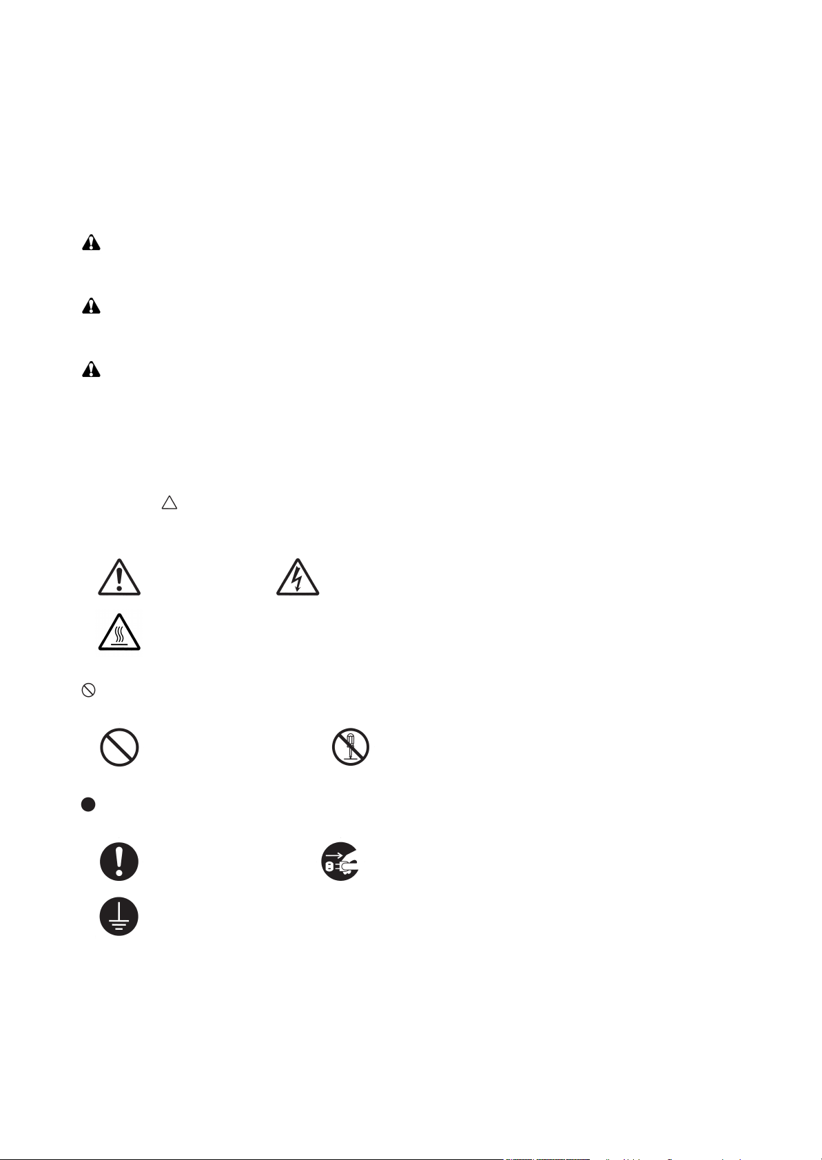
Symbols
The triangle ( ) symbol indicates a warning including danger and caution. The specific point of attention is
shown inside the symbol.
General warning. Warning of risk of electric shock.
Warning of high temperature.
indicates a prohibited action. The specific prohibition is shown inside the symbol.
General prohibited action. Disassembly prohibited.
indicates that action is required. The specific action required is shown inside the symbol.
General action required. Remove the power plug from the wall outlet.
Always ground the copier.

1. Installation Precautions
WARNING
• Do not use a power supply with a voltage other than that specified. Avoid multiple connections to
one outlet: they may cause fire or electric shock. When using an extension cable, always check that
it is adequate for the rated current. .....................................................................................................
• Connect the ground wire to a suitable grounding point. Not grounding the copier may cause fire or
electric shock. Connecting the earth wire to an object not approved for the purpose may cause
explosion or electric shock. Never connect the ground cable to any of the following: gas pipes, lightning rods, ground cables for telephone lines and water pipes or faucets not approved by the proper
authorities. ..........................................................................................................................................
CAUTION:
• Do not place the copier on an infirm or angled surface: the copier may tip over, causing injury. .........
• Do not install the copier in a humid or dusty place. This may cause fire or electric shock. .................
• Do not install the copier near a radiator, heater, other heat source or near flammable material. This
may cause fire. ...................................................................................................................................
• Allow sufficient space around the copier to allow the ventilation grills to keep the machine as cool
as possible. Insufficient ventilation may cause heat buildup and poor copying performance. ............
• Always handle the machine by the correct locations when moving it. .................................................
• Always use anti-toppling and locking devices on copiers so equipped. Failure to do this may cause
the copier to move unexpectedly or topple, leading to injury. ..............................................................
• Avoid inhaling toner or developer excessively. Protect the eyes. If toner or developer is accidentally
ingested, drink a lot of water to dilute it in the stomach and obtain medical attention immediately.
If it gets into the eyes, rinse immediately with copious amounts of water and obtain medical atten-
tion. .....................................................................................................................................................
• Advice customers that they must always follow the safety warnings and precautions in the copier’s
instruction handbook. .........................................................................................................................

2. Precautions for Maintenance
WARNING
• Always remove the power plug from the wall outlet before starting machine disassembly. ................
• Always follow the procedures for maintenance described in the service manual and other related
brochures. ..........................................................................................................................................
• Under no circumstances attempt to bypass or disable safety features including safety mechanisms
and protective circuits. ........................................................................................................................
• Always use parts having the correct specifications. ............................................................................
• Always use the thermostat or thermal fuse specified in the service manual or other related brochure
when replacing them. Using a piece of wire, for example, could lead to fire or other serious acci-
dent. ...................................................................................................................................................
• When the service manual or other serious brochure specifies a distance or gap for installation of a
part, always use the correct scale and measure carefully. ..................................................................
• Always check that the copier is correctly connected to an outlet with a ground connection. ...............
• Check that the power cable covering is free of damage. Check that the power plug is dust-free. If it
is dirty, clean it to remove the risk of fire or electric shock. .................................................................
• Never attempt to disassemble the optical unit in machines using lasers. Leaking laser light may
damage eyesight. ...............................................................................................................................
• Handle the charger sections with care. They are charged to high potentials and may cause electric
shock if handled improperly. ...............................................................................................................
CAUTION
• Wear safe clothing. If wearing loose clothing or accessories such as ties, make sure they are safely
secured so they will not be caught in rotating sections. ......................................................................
• Use utmost caution when working on a powered machine. Keep away from chains and belts. ..........
• Handle the fixing section with care to avoid burns as it can be extremely hot. ..................................
• Check that the fixing unit thermistor, heat and press rollers are clean. Dirt on them can cause
abnormally high temperatures. ...........................................................................................................

• Do not remove the ozone filter, if any, from the copier except for routine replacement. ......................
• Do not pull on the AC power cord or connector wires on high-voltage components when removing
them; always hold the plug itself. ........................................................................................................
• Do not route the power cable where it may be stood on or trapped. If necessary, protect it with a
cable cover or other appropriate item. ................................................................................................
• Treat the ends of the wire carefully when installing a new charger wire to avoid electric leaks. ..........
• Remove toner completely from electronic components. .....................................................................
• Run wire harnesses carefully so that wires will not be trapped or damaged. ......................................
• After maintenance, always check that all the parts, screws, connectors and wires that were
removed, have been refitted correctly. Special attention should be paid to any forgotten connector,
trapped wire and missing screws. .......................................................................................................
• Check that all the caution labels that should be present on the machine according to the instruction
handbook are clean and not peeling. Replace with new ones if necessary. .......................................
• Handle greases and solvents with care by following the instructions below: ......................................
· Use only a small amount of solvent at a time, being careful not to spill. Wipe spills off completely.
· Ventilate the room well while using grease or solvents.
· Allow applied solvents to evaporate completely before refitting the covers or turning the power
switch on.
· Always wash hands afterwards.
• Never dispose of toner or toner bottles in fire. Toner may cause sparks when exposed directly to
fire in a furnace, etc. ...........................................................................................................................
• Should smoke be seen coming from the copier, remove the power plug from the wall outlet immedi-
ately. ...................................................................................................................................................
3. Miscellaneous
WARNING
• Never attempt to heat the drum or expose it to any organic solvents such as alcohol, other than the
specified refiner; it may generate toxic gas. ........................................................................................
• Keep the machine away from flammable liquids, gases, and aerosols. A fire or an electric shock
might occur. ........................................................................................................................................

This page is intentionally left blank.

2LV/2L1/2L2/2MS/2MT-1
CONTENTS
1-1 Specifications
1-1-1 Specifications ........................................................................................................................ 1-1-1
1-1-2 Parts names .......................................................................................................................... 1-1-4
(1) Machine (front side).......................................................................................................... 1-1-4
(2) Machine (rear side)........................................................................................................... 1-1-6
(3) Operation section ............................................................................................................. 1-1-7
1-1-3 Machine cross section ........................................................................................................... 1-1-8
(1) 60/50/45 ppm model......................................................................................................... 1-1-8
(2) 40 ppm model...................................................................................................................1-1-9
1-2 Installation
1-2-1 Installation environment......................................................................................................... 1-2-1
1-2-2 Unpacking and installation..................................................................................................... 1-2-2
1-2-3 Install the expansion memory (option)................................................................................. 1-2-12
1-2-4 Install the memory card (SD card) (option).......................................................................... 1-2-13
1-2-5 Option composition.............................................................................................................. 1-2-14
1-3 Maintenance Mode
1-3-1 Service mode......................................................................................................................... 1-3-1
(1) Executing a service mode ................................................................................................ 1-3-1
(2) Description of service mode ............................................................................................. 1-3-2
(3) Printing an event log....................................................................................................... 1-3-16
1-4 Troubleshooting
1-4-1 Paper misfeed detection ........................................................................................................ 1-4-1
(1) Paper misfeed indication .................................................................................................. 1-4-1
(2) Paper misfeed detection condition ................................................................................... 1-4-1
(2-1) PF-320 (500 sheets Paper feeder)......................................................................... 1-4-1
(2-2) PF-315+ (Bulk Paper Feeder) ................................................................................ 1-4-2
1-4-2 Self-diagnostic function ......................................................................................................... 1-4-8
(1) Self-diagnostic function .................................................................................................... 1-4-8
(2) Self diagnostic codes........................................................................................................ 1-4-8
1-4-3 Image formation problems ................................................................................................... 1-4-24
(1) No image appears (entirely white).................................................................................. 1-4-25
(2) No image appears (entirely black).................................................................................. 1-4-25
(3) Image is too light. ........................................................................................................... 1-4-26
(4) The background is colored. ............................................................................................ 1-4-27
(5) White streaks are printed vertically................................................................................. 1-4-27
(6) Black streaks are printed vertically. ................................................................................ 1-4-28
(7) Streaks are printed horizontally. ..................................................................................... 1-4-28
(8) Spots are printed. ...........................................................................................................1-4-28
(9) Image is blurred.............................................................................................................. 1-4-29
(10) Paper is wrinkled. ........................................................................................................... 1-4-29
(11) Offset occurs. .................................................................................................................1-4-29
(12) Part of image is missing. ................................................................................................ 1-4-29
(13) Fusing is loose................................................................................................................ 1-4-30
(14) Image is out of focus. ..................................................................................................... 1-4-30
(15) Carrier leaking occurs..................................................................................................... 1-4-30
1-4-4 Electric problems ................................................................................................................. 1-4-31
1-4-5 Mechanical problems........................................................................................................... 1-4-35

2LV/2L1/2L2/2MS/2MT-2
1-5 Assembly and disassembly
1-5-1 Precautions for assembly and disassembly........................................................................... 1-5-1
(1) Precautions....................................................................................................................... 1-5-1
(2) Drum unit .......................................................................................................................... 1-5-1
(3) Toner ................................................................................................................................ 1-5-1
(4) How to tell a genuine Kyocera toner container................................................................. 1-5-2
1-5-2 Outer covers .......................................................................................................................... 1-5-3
(1) Detaching and refitting the top cover................................................................................ 1-5-3
(2) Detaching and refitting the inlet cover and slot cover....................................................... 1-5-3
(3) Detaching and refitting the right upper cover.................................................................... 1-5-4
(4) Detaching and refitting the right lower cover .................................................................... 1-5-4
(5) Detaching and refitting the rear left cover......................................................................... 1-5-5
(6) Detaching and refitting the left upper cover...................................................................... 1-5-5
(7) Detaching and refitting the left lower cover ...................................................................... 1-5-6
(8) Detaching and refitting the rear cover .............................................................................. 1-5-6
1-5-3 Paper feed section................................................................................................................. 1-5-8
(1) Detaching and refitting the paper feed roller .................................................................... 1-5-8
(2) Detaching and refitting the retard roller ............................................................................ 1-5-8
(3) Detaching and refitting the MP paper feed pulley............................................................. 1-5-9
1-5-4 Developer section ................................................................................................................ 1-5-13
(1) Detaching and refitting the developer unit ...................................................................... 1-5-13
1-5-5 Drum section ....................................................................................................................... 1-5-15
(1) Detaching and refitting the drum unit.............................................................................. 1-5-15
(2) Detaching and refitting the chager roller unit.................................................................. 1-5-15
1-5-6 Transfer/separation section ................................................................................................. 1-5-16
(1) Detaching and refitting the transfer roller assembly ....................................................... 1-5-16
(2) Detaching and refitting the separation needle unit ......................................................... 1-5-17
1-5-7 Optical section ..................................................................................................................... 1-5-18
(1) Detaching and refitting the laser scanner unit ................................................................ 1-5-18
1-5-8 Fuser section ....................................................................................................................... 1-5-19
(1) Detaching and refitting the fuser unit.............................................................................. 1-5-19
1-5-9 ejection section .................................................................................................................... 1-5-21
(1) Detaching and refitting the ejection unit ......................................................................... 1-5-21
1-5-10 PWBs................................................................................................................................... 1-5-22
(1) Detaching and refitting the main PWB............................................................................ 1-5-22
(2) Detaching and refitting the engine PWB......................................................................... 1-5-22
(3) Detaching and refitting the relay-L PWB ........................................................................ 1-5-24
(4) Detaching and refitting the power source PWB.............................................................. 1-5-25
(5) Detaching and refitting the high voltage PWB ................................................................ 1-5-26
(6) Detaching and refitting the operation PWB .................................................................... 1-5-28
1-5-11 Others .................................................................................................................................. 1-5-29
(1) Detaching and refitting the main driving motor unit ........................................................ 1-5-29
(2) Detaching and refitting the paper feed driving motor unit............................................... 1-5-30
(3) Detaching and refitting the power source fan motor....................................................... 1-5-30
(4) Direction of installing the principal fan motors ................................................................ 1-5-31
1-6 Requirements on PWB Replacement
1-6-1 Upgrading the firmware ......................................................................................................... 1-6-1
1-6-2 Remarks on PWB replacement ............................................................................................. 1-6-3
(1) Engine PWB ..................................................................................................................... 1-6-3

2LV/2L1/2L2/2MS/2MT-3
2-1 Mechanical Construction
2-1-1 Paper feed/conveying section ............................................................................................... 2-1-1
(1) Cassette paper feed section............................................................................................. 2-1-1
(2) MP tray paper feed section............................................................................................... 2-1-2
(3) Conveying section ............................................................................................................2-1-3
2-1-2 Drum section ......................................................................................................................... 2-1-4
(1) Charger roller unit............................................................................................................. 2-1-4
(2) Cleaning unit..................................................................................................................... 2-1-5
2-1-3 Developer section .................................................................................................................. 2-1-6
2-1-4 Optical section ....................................................................................................................... 2-1-7
(1) Laser scanner section ...................................................................................................... 2-1-7
2-1-5 Transfer/Separation section ..................................................................................................2-1-8
2-1-6 Fuser section ......................................................................................................................... 2-1-9
2-1-7 Eject/Feedshift section ........................................................................................................ 2-1-11
2-1-8 Duplex conveying section.................................................................................................... 2-1-13
2-2 Electrical Parts Layout
2-2-1 Electrical parts layout ............................................................................................................ 2-2-1
(1) PWBs................................................................................................................................ 2-2-1
(2) Switches and sensors....................................................................................................... 2-2-3
(3) Motors............................................................................................................................... 2-2-5
(4) Clutches and others.......................................................................................................... 2-2-7
2-3 Operation of the PWBs
2-3-1 Main PWB (MPWB) ............................................................................................................... 2-3-1
2-3-2 Engine PWB (EPWB) ............................................................................................................2-3-6
2-3-3 Power source PWB (PSPWB) ............................................................................................. 2-3-13
2-3-4 Relay-L PWB (R-LPWB)......................................................................................................2-3-15
2-3-5 High voltage PWB (HVPWB)............................................................................................... 2-3-18
2-4 Appendixes
2-4-1 Appendixes ............................................................................................................................ 2-4-1
(1) Maintenance kits............................................................................................................... 2-4-1
(2) Repetitive defects gauge .................................................................................................. 2-4-2
(3) Firmware environment commands ................................................................................... 2-4-3
(4) System Error (Fxxxx) Outline ......................................................................................... 2-4-11
(5) Wiring diagram (60/50/45 ppm model) ........................................................................... 2-4-21
(6) Wiring diagram (40ppm model) ...................................................................................... 2-4-23
Installation Guide
500 sheets paper feeder
2000 sheets bulk paper feeder
SSD (HD-6)
IEEE1284 Interface
Network interface
Wireless LAN interface

2LV/2L1/2L2/2MS/2MT
This page is intentionally left blank.

1-1 Specifications
1-1-1 Specifications
2LV/2L1/2L2/2MS/2MT
Item
Specifications
60 ppm 50 ppm 45 ppm 40 ppm
Typ e Desktop
Printing method Electrophotography by semiconductor laser
Paper
weight
Cassette 60 to 120 g/m
MP tray 60 to 220 g/m
Cassette
Plain, Recycled, Bond, Color (Colour), Preprinted, Letterhead,
Prepunched, Rough, High quality, Custom 1 to 8
2
2
, 230 g/m
2
(Postcard)
Paper
type
MP tray
Plain, Recycled, Bond, Color (Colour), Preprinted, Letterhead,
Prepunched, Rough, High quality, Label, Transparency, Postcard, Vellum,
Thick, Envelope, Custom 1 to 8
Legal, Oficio II, Mexican Oficio, Letter, Executive, Statement, Folio, A4,
Cassette
B5(JIS), A5, B6 *1, A6 *1, Return postcard *1, B5(ISO), C5, DL *1, 16K,
Custom
Paper
size
MP tray
Legal, Oficio II, Mexican Oficio, Letter, Executive, Statement, Folio, A4,
B5(JIS), A5, B6, A6, Return postcard, Postcard, B5(ISO), C5, Commercial
#10, DL, Commercial #9, Monarch, Commercial #6-3/4, Youkei4, Youkei2,
16K, Custom
*1: 60/50/45 ppm model only
Printing
speed
(ppm)
Full speed
Printing
speed
(ppm)
Half speed
[Simplex]
A4/Letter
-/Legal
B5R
A5R
A6R
[Duplex]
A4/Letter
-/Legal
B5R
A5R
[Simplex]
A4/Letter
-/Legal
B5R
A5R
A6R
[Duplex]
A4/Letter
-/Legal
B5R
A5R
60/62
- /50
48
32
32
43/44
- /25
34
23
30/31
- /25
24
16
16
21.5/22
- /12.5
17
11.5
50/52
- /42
40
27
27
36/37
- /21
28
19
25/26
- /21
20
13.5
13.5
18/18.5
- /10.5
14
9.5
45/47
- /38
36
23
23
32/33
- /16
25
16
22.5/23.5
- /19
18
11.5
11.5
16/16.5
- /8
12.5
8
40/42
- /33
33
22
22
20/21
- /16.5
16.5
11
20/21
- /17
16.5
11
11
10/10.5
- /8
8
5.5
1-1-1

2LV/2L1/2L2/2MS/2MT-1
Item
60 ppm 50 ppm 45 ppm 40 ppm
Resolution
First print time
Fine1200, Fast1200(KIR), 600dpi(KIR) , 300dpi
9.0 s or less
(A4, feed from cassette)
Warm-up
time
(22 °C/
71.6 °F,
60% RH)
Paper
capacity
Output tray
capacity
Power on/
Off mode/
25 s or less
Sleep mode
Low power
mode
-
Cassette 500 sheets (80g/m
MP tray 100 sheets (80 g/m
Facedown
500 sheets (67g/m
Faceup 250 sheets (67g/m
2
2
2
Photoconductor a-Si drum (diameter 30 mm)
Image write system Semiconductor laser
Charging system Contact charger roller method
Specifications
20 s or less 15 s or less 15 s or less
)
2
)
)
250 sheets
(67g/m
)
2
)
-
Developer system
Mono component dry developing method
Toner replenishing: Automatic from the toner container
Transfer system Transfer roller method
Separation system Small diameter separation, dischager needle (DC bias)
Cleaning system Counter blade cleaning + cleaning roller
Charge erasing system Exposure by cleaning lamp (LED)
Heat and pressure fusing with the heat roller and the press roller
Fusing system
Heat source: halogen heater
Abnormally high temperature protection devices: thermostat
CPU PowerPC465, ARM7/ARM9 PowerPC465 *1
Main memory 256 MB / 1280 MB (Standard / Max) *2
Windows XP, Windows XP Professional,
Windows Server 2003, Windows Server 2003 x64 Edition,
Operating system
Windows Vista x86 Edition, Windows Vista x64 Edition,
Windows 7 x86 Edition, Windows 7 x64 Edition,
Windows Server 2008, Windows Server 2008 x64 Edition,
Apple Macintosh OS X
USB device interface connector: 1 (USB 2.0)
Standard
Interface
Option
USB host interface connector: 2 (USB 2.0)
Network interface connector: 1 (10BASE-T/100BASE-TX/1000BASE-T) *3
eKUIO slot: 1
Page description language PRESCRIBE
Emulation PCL6, KPDL3, XPS, Line printer, IBM Proprinter X24E, EPSON LQ-850
1-1-2
2LV/2L1/2L2/2MS/2MT-1
Item
Tem perature 10 to 32.5 °C/50 to 90.5 °F
Operating
environment
Dimensions (W × D × H)
(with toner container)
Space required (W × D)
Humidity 15 to 80% RH
Altitude 2,500 m/8,202 ft or less
Brightness 1,500 lux or less
Weight
Specifications
60 ppm 50 ppm 45 ppm 40 ppm
380 × 416 × 320 mm / 14 15/16” × 16 3/8 “× 12 1/4”
14.6 kg / 32.2 lb
380 × 593 mm / 14 15/16” × 23 3/8” (using MP tray)
380 × 1138 mm / 14 15/16” × 44 13/16”
(using 2000 sheets paper feeder + Faceup tray)
380 × 416 × 285
14 15/16” × 16 3/
8 “× 11 1/4”
13.5kg/29.8lb
380 × 799 mm /
14 15/16” × 31 7/
16”
(using 2000
sheets paper
feeder)
Power source
120 V AC, 60 Hz
220 - 240 V AC, 50/60 Hz
Options
more than 10.0 A
more than 6.0 A
500 sheets paper feeder, 2000 sheets bulk paper feeder, Faceup tray *4,
SSD (HD-6), IEEE1284 Interface, Network interface,
Wireless LAN interface, Expanded memory, SD card,
Card Authentication Kit, IC card reader, Data Security Kit(E), USB keyboard,
UG-33(Thin print)
*1: 40 ppm (without Network) model ;
*2: 40 ppm (without Network) model ; 128 MB / 1152 MB (Standard / Max)
*3: 40 ppm (without Network) model ; Network interface connector : 0
*4: 60/50/45 ppm model only
NOTE: These specifications are subject to change without notice.
1-1-3
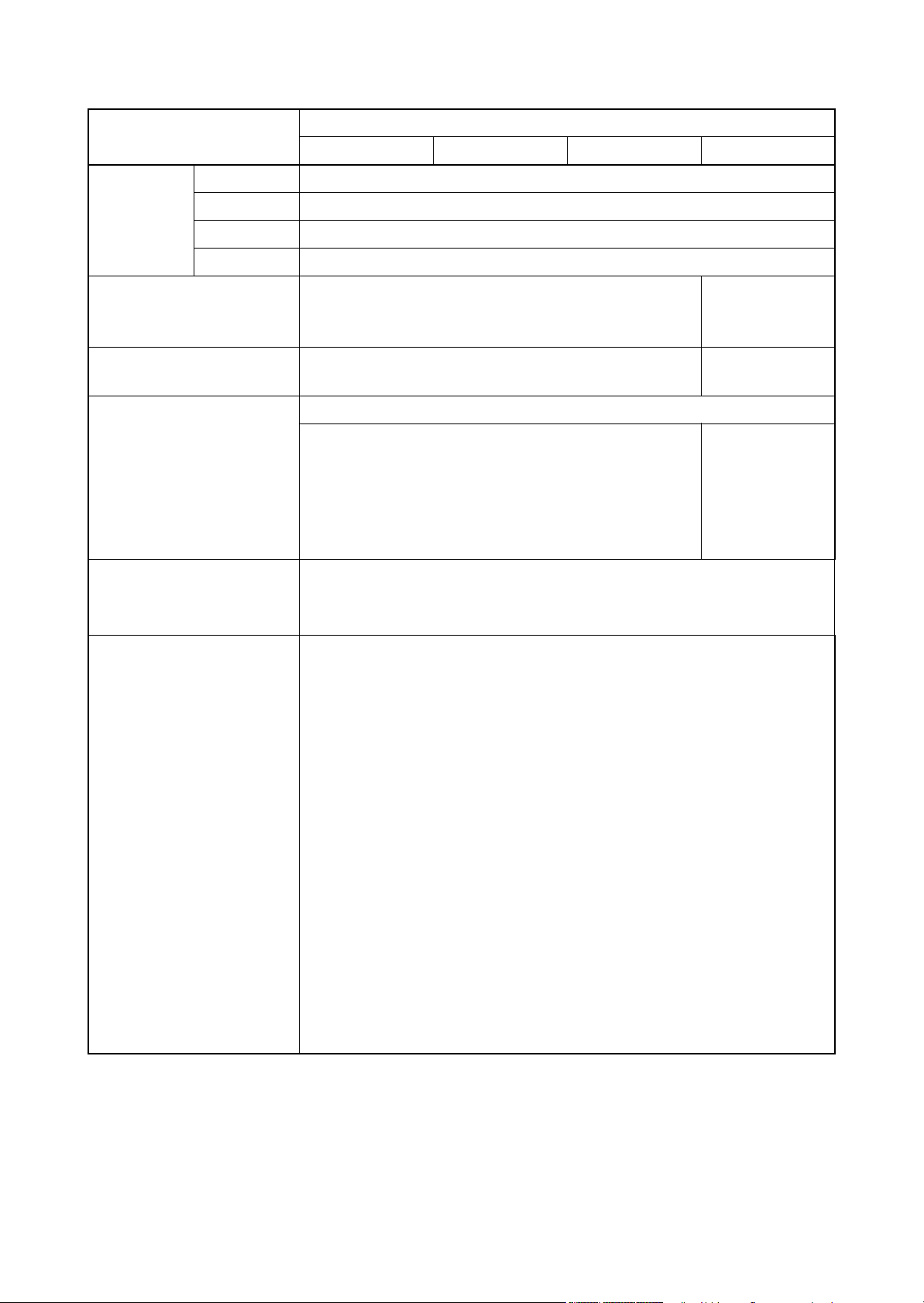
1-1-2 Parts names
1. Machine
2. Power switch
3. Cassette
4. Paper size label
5. Paper width guides
6. Paper length guide
7. USB memory slot
8. Top cover
9. Toner container
10. Lock lever (Toner container)
11. Developer unit
(1) Machine (front side)
11
2LV/2L1/2L2/2MS/2MT
8
9
5
1
10
7
2
3
6
5
4
Figure 1-1-1
1-1-4
2LV/2L1/2L2/2MS/2MT
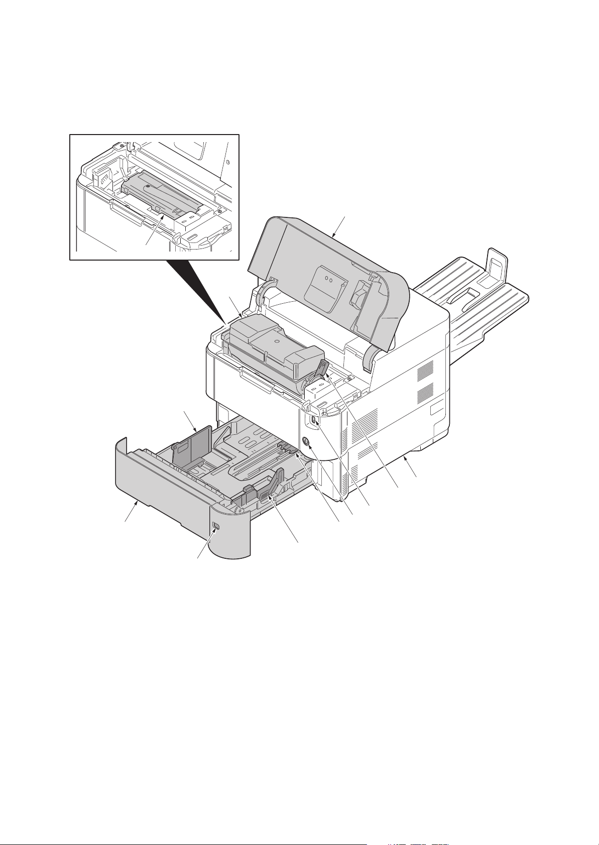
12. Operation panel
13. MP (multi purpose) tray
14. MP middle tray
15. MP top tray
16. MP Paper width guides
17. MP paper feed roller
18. Left cover
19. Waste toner box
20. Top tray (facedown)
21. Eject roller
18
21
19
20
12
17
16
15
14
13
16
Figure 1-1-2
1-1-5
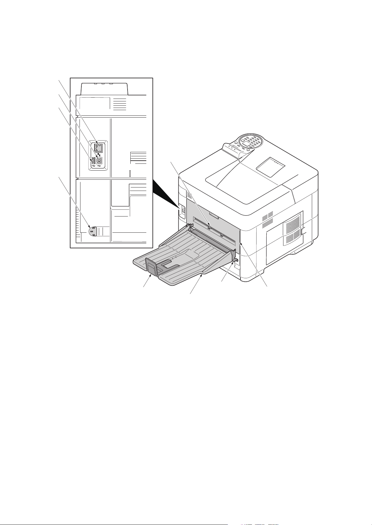
(2) Machine (rear side)
22. Rear cover
23. Faceup roller *1
24. Tray attachment plate *2
25. Faceup tray *2
26. Paper stopper *2
27. Network interface connector *3
28. USB interface connector
29. USB port
30. Power cord connector
*1: 60/50/45 ppm model only
*2: 60/50/45 ppm model only (Option)
*3: Except 40 ppm model
(without Network)
27
28
29
30
2LV/2L1/2L2/2MS/2MT
23
26
24
25
Figure 1-1-3
1-1-6
22

(3) Operation section
RReadyeady DataData
AttentioAttention
Logout
Cancel
BackBack
ClearClear
Documement Box
Menuenu
39
37
31
35
40
43
42
38
34
33
36
32
44
45
41
31. Ready indicator
32. Data indicator
33. Attention indicator
34. Message display
35. Left select key
36. Right select key
37. Logout key
38. Cancel key
39. Menu key
40. Back key
41. Numeric keys
42. Cursor keys
43. OK key
44. Clear key
45. Document box key
2LV/2L1/2L2/2MS/2MT
Figure 1-1-4
1-1-7
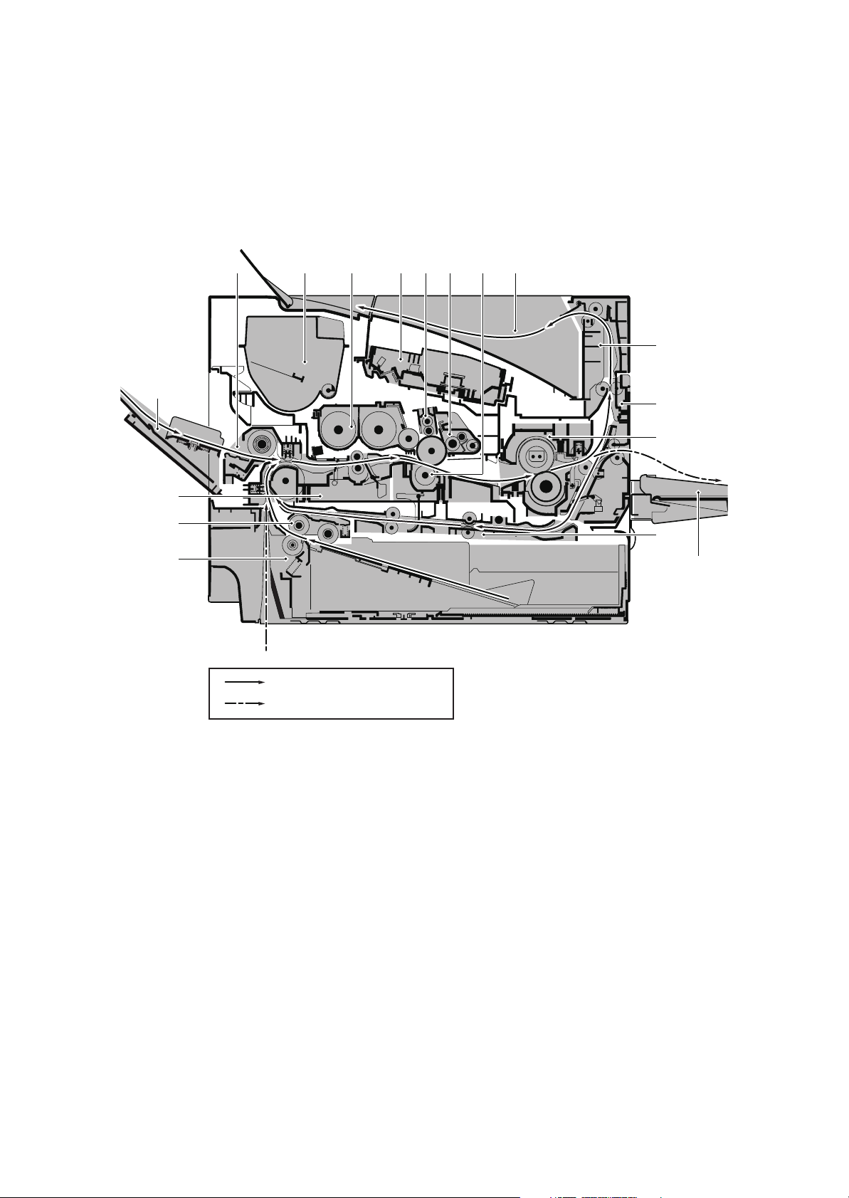
1-1-3 Machine cross section
1. Cassette
2. Cassette paper feed section
3. Paper feed conveying section
4. MP tray
5. MP tray paper feed section
6. Toner container
7. Developer unit
8. Laser scanner unit (LSU)
9. Charger roller unit
10. Drum unit
11. Transfer/Separation section
12. Eject tray (facedown)
13. Eject section
14. Eject conveying section
15. Fuser unit
16. Duplex conveyning section
17. Faceup tray (option)
(1) 60/50/45 ppm model
5
7
96 128
2LV/2L1/2L2/2MS/2MT-1
10 11
13
4
14
15
3
2
1
Paper path
Paper path (Option)
16
17
Figure 1-1-5
1-1-8
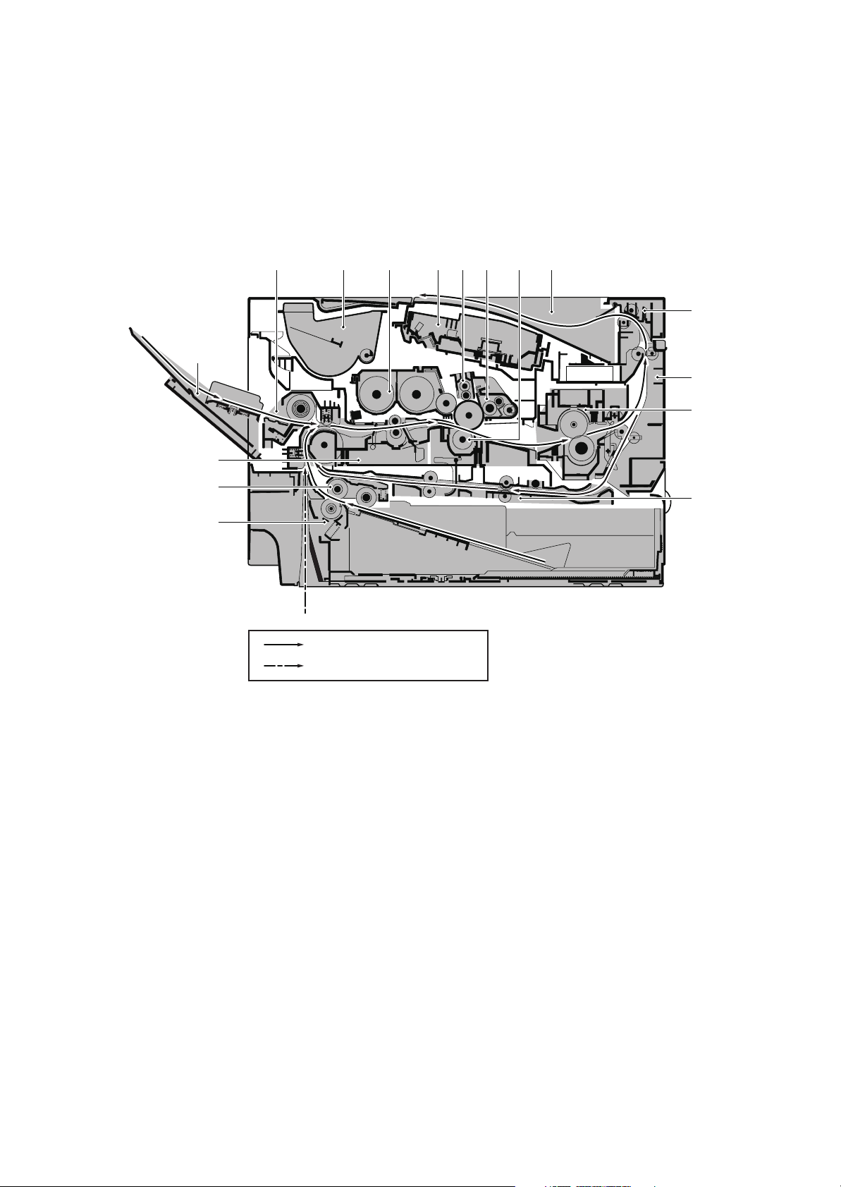
(2) 40 ppm model
1. Cassette
2. Cassette paper feed section
3. Paper feed conveying section
4. MP tray
5. MP tray paper feed section
6. Toner container
7. Developer unit
8. Laser scanner unit (LSU)
9. Charger roller unit
10. Drum unit
11. Transfer/Separation section
12. Eject tray (facedown)
13. Eject section
14. Eject conveying section
15. Fuser unit
16. Duplex conveyning section
2LV/2L1/2L2/2MS/2MT-1
5
7
10 1196 128
13
4
14
15
3
2
16
1
Paper path
Paper path (Option)
Figure 1-1-6
1-1-9

2LV/2L1/2L2/2MS/2MT
This page is intentionally left blank.
1-1-10
2LV/2L1/2L2/2MS/2MT
1-2 Installation
1-2-1 Installation environment
1. Temperature: 10 to 32.5°C/50 to 90.5°F
2. Humidity: 15 to 80% RH
3. Power supply: 120 V AC, 12.0 A
220 - 240 V AC, 6.5 A
4. Power supply frequency: 50 Hz ±2%/60 Hz ±2%
5. Installation location
Avoid direct sunlight or bright lighting. Ensure that the photoconductor will not be exposed to direct sunlight or other strong light when removing paper jams.
Avoid locations subject to high temperature and high humidity or low temperature and low humidity; an
abrupt change in the environmental temperature; and cool or hot, direct air.
Avoid places subject to dust and vibrations.
Choose a surface capable of supporting the weight of the machine.
Place the machine on a level surface (maximum allowance inclination: 1°).
Avoid air-borne substances that may adversely affect the machine or degrade the photoconductor, such
as mercury, acidic of alkaline vapors, inorganic gasses, NOx, SOx gases and chlorine-based organic solvents.
Select a well-ventilated location.
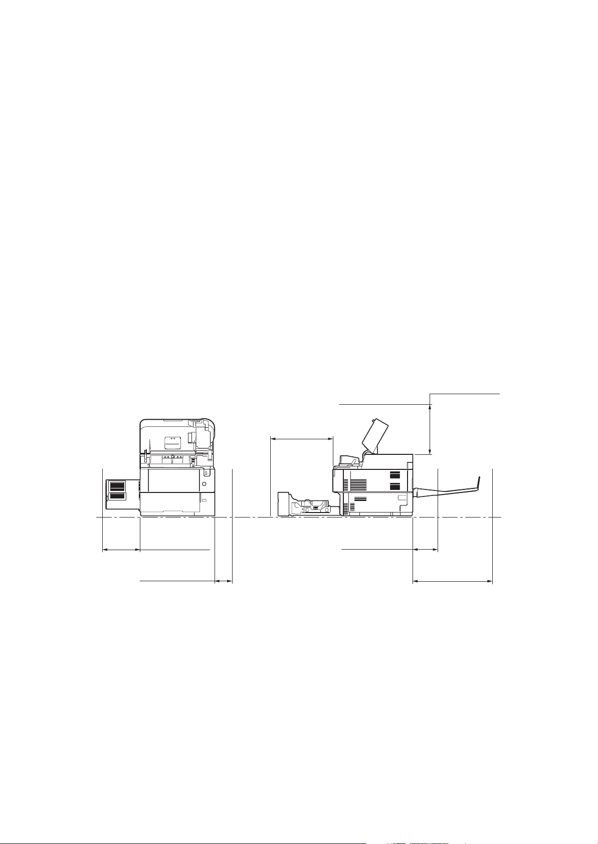
6. Allow sufficient access for proper operation and maintenance of the machine.
300mm or more
11
13/16”
or more
100mm or more
15/16”
3
or more
500mm or more
19
11/16”
or more
*1: Without the faceup tray
*2: With the faceup tray (60/50/45 ppm model)
Figure 1-2-1
200mm or more
7
7/8”
or more *1
400mm or more
3/4”
or more
15
400mm or more
15
3/4”
or more *2
1-2-1
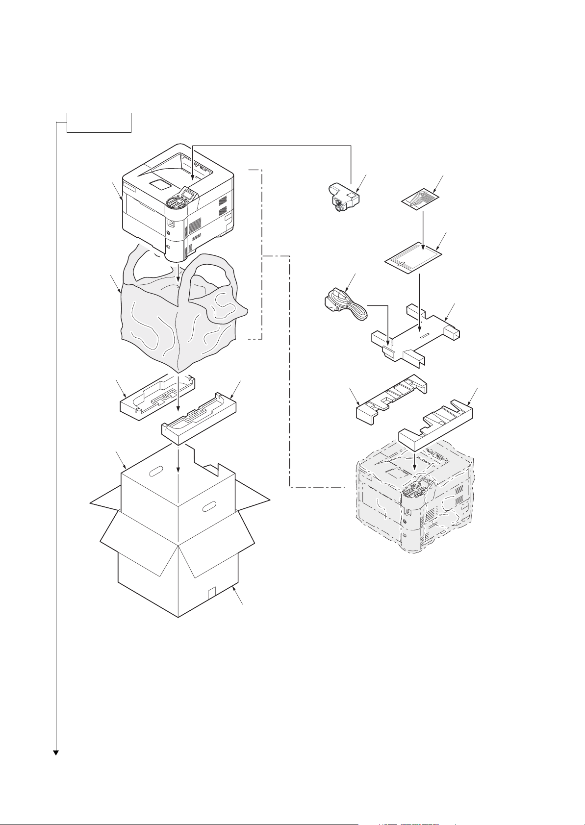
1-2-2 Unpacking and installation
Unpacking
1. Outer case
2. Inner case
3. Bottom pad R
4. Bottom pad L
5. Machine cover (740 × 700)
6. Machine
7. Upper pad R
8. Upper pad L
9. Top tray
10. Operation guide
11. Operation sheets Assy *1
12. Waste toner bottle
13. Power cord
*1: Except 240V model
2LV/2L1/2L2/2MS/2MT-2
12
11
6
10
5
13
9
4
3
8
7
2
1
Caution: Place the machine on a level surface.
Figure 1-2-2
1-2-2
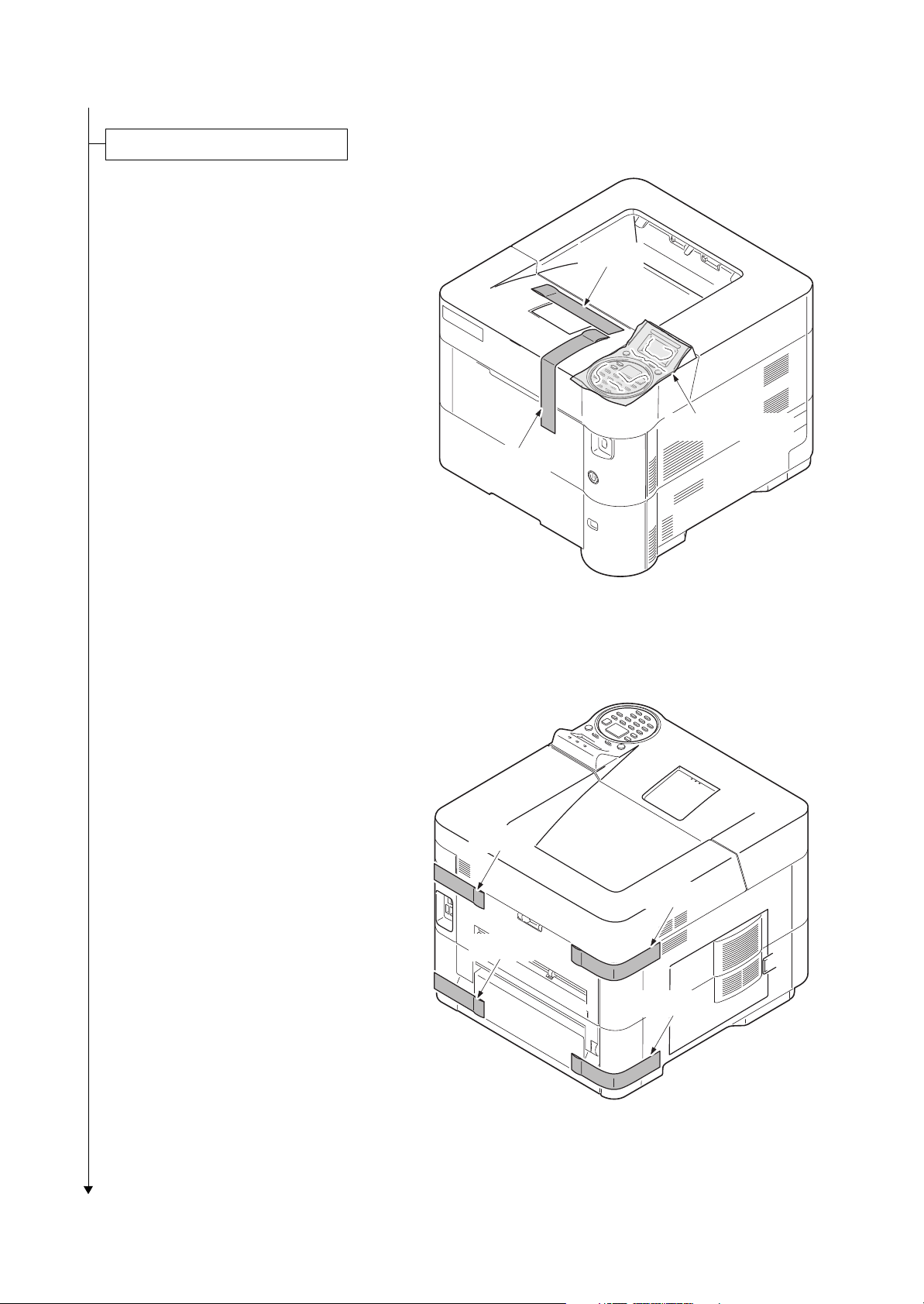
Removing the tapes and pads
1. Remove two tapes.
2. Remove the protection sheet.
2LV/2L1/2L2/2MS/2MT
Ta pe
Protection sheet
Ta pe
3. Remove four tapes.
Figure 1-2-3
Tape
Tape
Tape
Tape
Figure 1-2-4
1-2-3
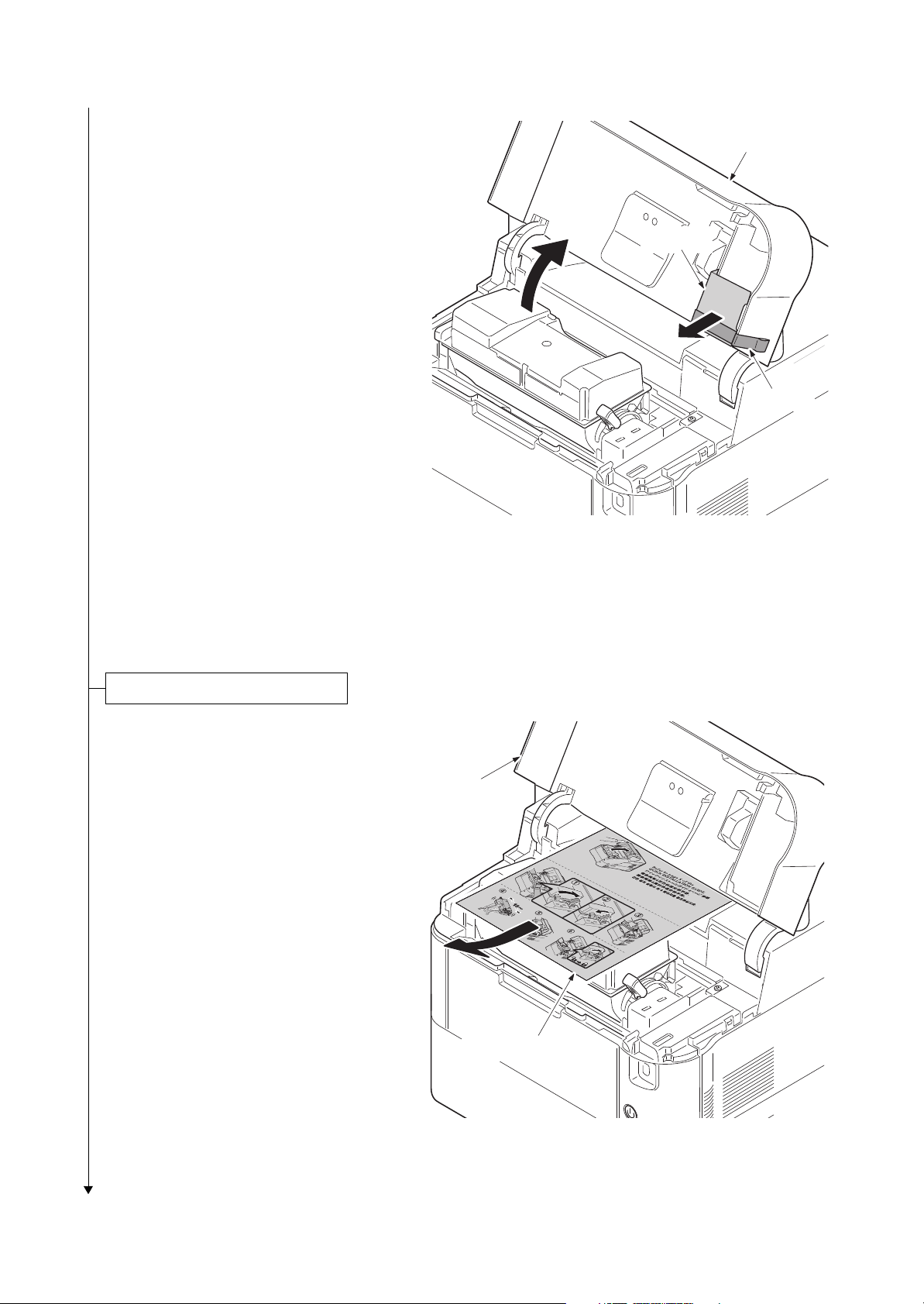
(60/50/45 ppm model only)
Tape
Top cover
Spacer
Installing the toner container
Container label
Top cover
4. Open the top cover.
5. Remove the tape and the spacer.
2LV/2L1/2L2/2MS/2MT-1
Figure 1-2-5
1. Open the top cover.
2. Remove the container label by pulling
forwards.
Caution: Check the contents of the
container label and remove a container.
Figure 1-2-6
1-2-4
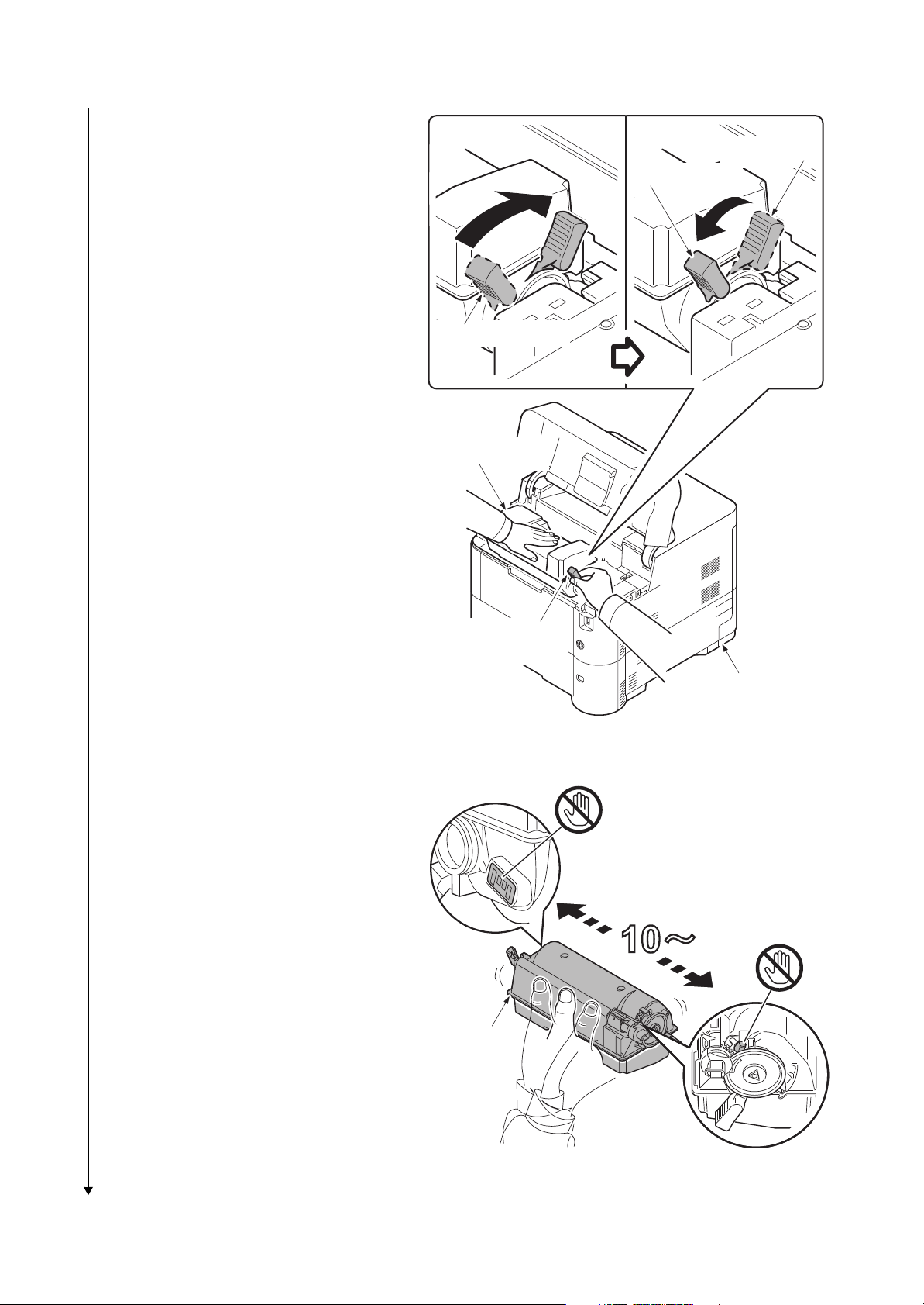
3. Rotate the toner container lock lever to
the lock position and then remove the
toner container from the printer by
returning it to the unlock position.
2LV/2L1/2L2/2MS/2MT
Lock position
Unlock position
Shipment position
Toner container
4. Shake the turned toner container 10
times or more as shown in the figure in
order to distribute the toner evenly
inside the container.
Caution:Do not press too firmly on the
center of the toner container or touch
the toner feed slot or the terminal parts.
5. Set the toner container to the printer
and then turn the toner container lock
lever to the lock position.
6. Close the top cover.
Toner container
lock lever
Printer
Figure 1-2-7
Terminal parts
Toner feed slot
To ne r
container
1-2-5
Figure 1-2-8
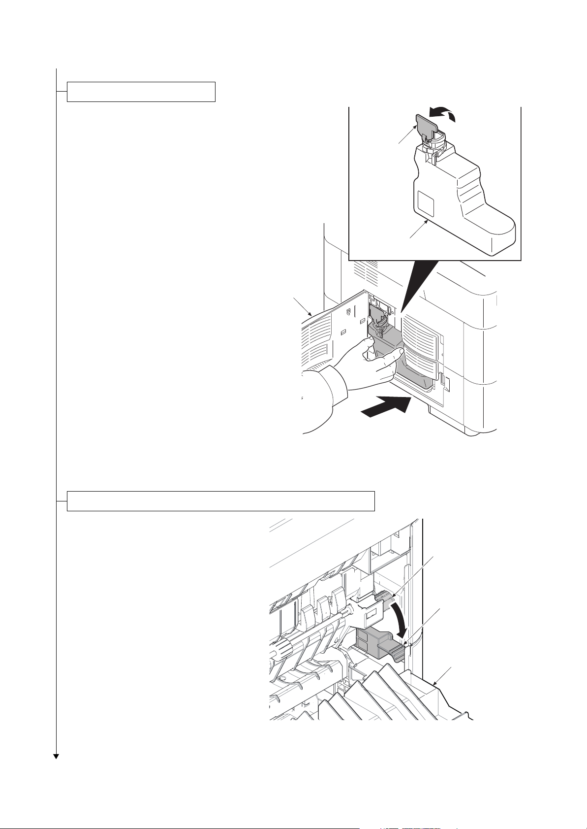
1. Openthe left cover.
Installing the waste toner box
Waste toner box
Cap
Left cover
Setting of the fuser pressure release lever (40 ppm model only)
2. Open the cap of the waste toner box.
3. Install the waste toner box.
4. Close the left cover.
2LV/2L1/2L2/2MS/2MT-1
1. Open the rear cover.
2. Push the release lever down for
changing the lever position to a normal
position from a shipment position.
3. Close the rear cover.
Figure 1-2-9
Release lever
(Shipment position)
Release lever
(Normal position)
Rear cover
Figure 1-2-10
1-2-6
Loading...