


 Loading...
FS-1028MFP
SERVICE
MANUAL
Published in December 2009
842H9113
2H9SM063
Rev.3
CAUTION
RISK OF EXPLOSION IF BATTERY IS REPLACED BY AN INCORRECT TYPE. DISPOSE OF USED BATTERIES ACCORDING TO THE INSTRUCTIONS.
It may be illegal to dispose of this battery into the municipal waste stream. Check with your local solid waste officials for details in your area for proper disposal.
ATTENTION
IL Y A UN RISQUE D’EXPLOSION SI LA BATTERIE EST REMPLACEE PAR UN MODELE DE TYPE INCORRECT. METTRE AU REBUT LES BATTERIES UTILISEES SELON LES INSTRUCTIONS DONNEES.
Il peut être illégal de jeter les batteries dans des eaux d’égout municipales. Vérifiez avec les fonctionnaires municipaux de votre région pour les détails concernant des déchets solides et une mise au rebut appropriée.
Revision history
Revision |
Date |
Replaced pages |
Remarks |
|
|
|
|
1 |
June 24, 2009 |
1-1-1, 1-1-3, 1-1-4, 1-2-2, 1-3-1 to 1-3-64, 1-4-3, |
- |
|
|
1-4-5, 1-4-6, 1-4-7, 1-4-9, 1-5-3, 1-5-12, 1-5-21, |
|
|
|
1-5-29, 1-5-30, 1-5-22, 1-5-23, 1-5-24, 1-5-25, |
|
|
|
1-5-26, 1-5-27, 1-5-29, 1-5-30, 1-5-49, 2-1-8, 2-2-2, |
|
|
|
2-2-4, 2-3-2, 2-4-2, 2-4-4 |
|
|
|
|
|
2 |
August 11, 2009 |
1-3-3 to 1-3-10, 1-3-16, 1-3-17, 1-3-31 to 1-3-34, |
- |
|
|
1-3-36, 1-3-42, 1-3-51, 1-5-2, 1-5-29, 1-5-30 |
|
|
|
|
|
3 |
December 24, 2009 |
CONTENTS, 1-1-1, 1-1-2, 1-3-6 to 1-3-9 |
- |
|
|
|
|

This page is intentionally left blank.

Safety precautions
This booklet provides safety warnings and precautions for our service personnel to ensure the safety of their customers, their machines as well as themselves during maintenance activities. Service personnel are advised to read this booklet carefully to familiarize themselves with the warnings and precautions described here before engaging in maintenance activities.

Safety warnings and precautions
Various symbols are used to protect our service personnel and customers from physical danger and to prevent damage to their property. These symbols are described below:
 DANGER: High risk of serious bodily injury or death may result from insufficient attention to or incorrect compliance with warning messages using this symbol.
 WARNING: Serious bodily injury or death may result from insufficient attention to or incorrect compliance with warning messages using this symbol.
 CAUTION: Bodily injury or damage to property may result from insufficient attention to or incorrect compliance with warning messages using this symbol.
Symbols
The triangle ( ) symbol indicates a warning including danger and caution. The specific point of attention is shown inside the symbol.
General warning.
Warning of risk of electric shock.
Warning of high temperature.
 indicates a prohibited action. The specific prohibition is shown inside the symbol.
General prohibited action.
Disassembly prohibited.
 indicates that action is required. The specific action required is shown inside the symbol.
General action required.
Remove the power plug from the wall outlet.
Always ground the copier.

1.Installation Precautions
 WARNING
•Do not use a power supply with a voltage other than that specified. Avoid multiple connections to one outlet: they may cause fire or electric shock. When using an extension cable, always check that it is adequate for the rated current. .............................................................................................
•Connect the ground wire to a suitable grounding point. Not grounding the copier may cause fire or electric shock. Connecting the earth wire to an object not approved for the purpose may cause explosion or electric shock. Never connect the ground cable to any of the following: gas pipes, lightning rods, ground cables for telephone lines and water pipes or faucets not approved by the proper authorities. ............................................................................................................................
 CAUTION:
•Do not place the copier on an infirm or angled surface: the copier may tip over, causing injury. .......
•Do not install the copier in a humid or dusty place. This may cause fire or electric shock. ................
•Do not install the copier near a radiator, heater, other heat source or near flammable material.
This may cause fire. .........................................................................................................................
•Allow sufficient space around the copier to allow the ventilation grills to keep the machine as cool as possible. Insufficient ventilation may cause heat buildup and poor copying performance. ...........
•Always handle the machine by the correct locations when moving it. ...............................................
•Always use anti-toppling and locking devices on copiers so equipped. Failure to do this may cause the copier to move unexpectedly or topple, leading to injury. ...........................................................
•Avoid inhaling toner or developer excessively. Protect the eyes. If toner or developer is accidentally ingested, drink a lot of water to dilute it in the stomach and obtain medical attention immediately. If it gets into the eyes, rinse immediately with copious amounts of water and obtain medical attention. ......................................................................................................................................
•Advice customers that they must always follow the safety warnings and precautions in the copier’s instruction handbook. .....................................................................................................................

2.Precautions for Maintenance
 WARNING
•Always remove the power plug from the wall outlet before starting machine disassembly. ...............
•Always follow the procedures for maintenance described in the service manual and other related brochures. .......................................................................................................................................
•Under no circumstances attempt to bypass or disable safety features including safety mechanisms and protective circuits. .....................................................................................................................
•Always use parts having the correct specifications. ..........................................................................
•Always use the thermostat or thermal fuse specified in the service manual or other related brochure when replacing them. Using a piece of wire, for example, could lead to fire or other serious accident. ..........................................................................................................................................
•When the service manual or other serious brochure specifies a distance or gap for installation of a part, always use the correct scale and measure carefully. ................................................................
•Always check that the copier is correctly connected to an outlet with a ground connection. .............
•Check that the power cable covering is free of damage. Check that the power plug is dust-free. If it is dirty, clean it to remove the risk of fire or electric shock. ..............................................................
•Never attempt to disassemble the optical unit in machines using lasers. Leaking laser light may damage eyesight. ...........................................................................................................................
•Handle the charger sections with care. They are charged to high potentials and may cause electric shock if handled improperly. ............................................................................................................
CAUTION
•Wear safe clothing. If wearing loose clothing or accessories such as ties, make sure they are safely secured so they will not be caught in rotating sections. ..........................................................
•Use utmost caution when working on a powered machine. Keep away from chains and belts. ........
•Handle the fixing section with care to avoid burns as it can be extremely hot. ..................................
•Check that the fixing unit thermistor, heat and press rollers are clean. Dirt on them can cause abnormally high temperatures. ........................................................................................................

•Do not remove the ozone filter, if any, from the copier except for routine replacement. ....................
•Do not pull on the AC power cord or connector wires on high-voltage components when removing them; always hold the plug itself. .....................................................................................................
•Do not route the power cable where it may be stood on or trapped. If necessary, protect it with a cable cover or other appropriate item. .............................................................................................
•Treat the ends of the wire carefully when installing a new charger wire to avoid electric leaks. ........
•Remove toner completely from electronic components. ...................................................................
•Run wire harnesses carefully so that wires will not be trapped or damaged. ....................................
•After maintenance, always check that all the parts, screws, connectors and wires that were removed, have been refitted correctly. Special attention should be paid to any forgotten connector, trapped wire and missing screws. ...................................................................................................
•Check that all the caution labels that should be present on the machine according to the instruction handbook are clean and not peeling. Replace with new ones if necessary. ......................................
•Handle greases and solvents with care by following the instructions below: .....................................
·Use only a small amount of solvent at a time, being careful not to spill. Wipe spills off completely.
·Ventilate the room well while using grease or solvents.
·Allow applied solvents to evaporate completely before refitting the covers or turning the power switch on.
·Always wash hands afterwards.
•Never dispose of toner or toner bottles in fire. Toner may cause sparks when exposed directly to fire in a furnace, etc. .......................................................................................................................
•Should smoke be seen coming from the copier, remove the power plug from the wall outlet immediately. ............................................................................................................................................
3.Miscellaneous
 WARNING
•Never attempt to heat the drum or expose it to any organic solvents such as alcohol, other than the specified refiner; it may generate toxic gas. .....................................................................................

This page is intentionally left blank.
|
|
|
2H9-3 |
|
|
CONTENTS |
|
1-1 Specifications |
|
||
1-1-1 Specifications.......................................................................................................................................... |
1-1-1 |
||
1-1-2 |
Parts names............................................................................................................................................ |
1-1-3 |
|
|
(1) |
Overall ............................................................................................................................................... |
1-1-3 |
|
(2) |
Operation panel................................................................................................................................. |
1-1-4 |
1-1-3 |
Machine cross section ............................................................................................................................ |
1-1-5 |
|
1-2 Installation |
|
||
1-2-1 |
Installation environment .......................................................................................................................... |
1-2-1 |
|
1-2-2 Unpacking ............................................................................................................................................... |
1-2-2 |
||
|
(1) |
Unpacking ......................................................................................................................................... |
1-2-2 |
|
(2) |
Removing the tapes .......................................................................................................................... |
1-2-3 |
1-2-3 Installing the expansion memory (option) ............................................................................................... |
1-2-5 |
||
1-3 Maintenance Mode |
|
||
1-3-1 |
Maintenance mode ................................................................................................................................. |
1-3-1 |
|
|
(1) |
Executing a maintenance item .......................................................................................................... |
1-3-1 |
|
(2) |
Maintenance modes item list............................................................................................................. |
1-3-2 |
|
(3) |
Contents of the maintenance mode items......................................................................................... |
1-3-4 |
1-3-2 |
Management mode ............................................................................................................................... |
1-3-55 |
|
|
(1) |
Using the management mode ......................................................................................................... |
1-3-55 |
|
(2) |
Common Settings............................................................................................................................ |
1-3-56 |
|
(3) |
Copy Settings.................................................................................................................................. |
1-3-60 |
|
(4) |
Sending Settings ............................................................................................................................. |
1-3-60 |
|
(5) |
Document Box Settings................................................................................................................... |
1-3-60 |
|
(6) |
Printer Settings................................................................................................................................ |
1-3-61 |
|
(7) |
Printing Reports/Sending Notice ..................................................................................................... |
1-3-61 |
|
(8) |
Adjustment/Maintenance................................................................................................................. |
1-3-62 |
|
(9) |
Date/Timer....................................................................................................................................... |
1-3-62 |
|
(10) |
Editing Destination (Address Book/Adding One-Touch Keys) ........................................................ |
1-3-63 |
|
(11) |
Restarting the System..................................................................................................................... |
1-3-64 |
|
(12) |
Network Setup................................................................................................................................. |
1-3-64 |
|
(13) |
User Login Administration ............................................................................................................... |
1-3-66 |
|
(14) |
Job accounting ................................................................................................................................ |
1-3-66 |
1-4 Troubleshooting |
|
||
1-4-1 |
Paper misfeed detection ......................................................................................................................... |
1-4-1 |
|
|
(1) |
Paper misfeed indication ................................................................................................................... |
1-4-1 |
|
(2) |
Paper misfeed detection condition .................................................................................................... |
1-4-1 |
1-4-2 |
Self-diagnostic function........................................................................................................................... |
1-4-2 |
|
|
(1) |
Self-diagnostic function ..................................................................................................................... |
1-4-2 |
|
(2) |
Self diagnostic codes ........................................................................................................................ |
1-4-3 |
1-4-3 |
Image formation problems .................................................................................................................... |
1-4-10 |
|
|
(1) |
Completely blank printout................................................................................................................ |
1-4-11 |
|
(2) |
All-black printout.............................................................................................................................. |
1-4-11 |
|
(3) |
Dropouts.......................................................................................................................................... |
1-4-12 |
|
(4) |
Black dots........................................................................................................................................ |
1-4-12 |
|
(5) |
Black horizontal streaks. ................................................................................................................. |
1-4-12 |
|
(6) |
Black vertical streaks....................................................................................................................... |
1-4-13 |
|
(7) |
Unsharpness. .................................................................................................................................. |
1-4-13 |
|
(8) |
Gray background............................................................................................................................. |
1-4-13 |
|
(9) |
Dirt on the top edge or back of the paper........................................................................................ |
1-4-14 |
|
(10) |
Undulated printing at the right edge (scanning start position)......................................................... |
1-4-14 |
1-4-4 |
Electric problems .................................................................................................................................. |
1-4-15 |
|
1-4-5 |
Mechanical problems ............................................................................................................................ |
1-4-18 |
|
2H9
1-5 Assembly and Disassembly
1-5-1 |
Precautions for assembly and disassembly............................................................................................ |
1-5-1 |
|
|
(1) |
Precautions ....................................................................................................................................... |
1-5-1 |
|
(2) |
Drum.................................................................................................................................................. |
1-5-1 |
|
(3) |
Toner ................................................................................................................................................. |
1-5-1 |
|
(4) |
How to tell a genuine Kyocera Mita toner container.......................................................................... |
1-5-2 |
1-5-2 |
Outer covers ........................................................................................................................................... |
1-5-3 |
|
|
(1) |
Detaching and refitting the left cover and right cover ........................................................................ |
1-5-3 |
1-5-3 |
Paper feed section .................................................................................................................................. |
1-5-6 |
|
|
(1) |
Detaching and refitting the paper feed assembly (paper feed roller and pickup roller) ..................... |
1-5-6 |
|
(2) |
Detaching and refitting the retard roller assembly............................................................................. |
1-5-8 |
|
(3) |
Detaching and refitting the MP paper feed roller............................................................................. |
1-5-10 |
|
(4) |
Note on removing and Installing the upper registration roller and lower registration roller ............. |
1-5-12 |
1-5-4 |
Optical section ...................................................................................................................................... |
1-5-13 |
|
|
(1) |
Detaching and refitting the original cover ........................................................................................ |
1-5-13 |
|
(2) |
Detaching and refitting the scanner unit (LSU) ............................................................................... |
1-5-14 |
|
(3) |
Detaching and refitting the laser scanner unit (LSU)....................................................................... |
1-5-17 |
|
(4) |
Replacing the image scanner unit (ISU).......................................................................................... |
1-5-21 |
|
(5) |
Detaching and refitting the exposure lamp and inverter PWB......................................................... |
1-5-27 |
1-5-5 |
Developing section................................................................................................................................ |
1-5-29 |
|
|
(1) |
Detaching and refitting the developing unit ..................................................................................... |
1-5-29 |
1-5-6 |
Drum section......................................................................................................................................... |
1-5-30 |
|
|
(1) |
Detaching and refitting the drum unit .............................................................................................. |
1-5-30 |
|
(2) |
Detaching and refitting the main charger unit.................................................................................. |
1-5-31 |
1-5-7 |
Transfer/separation section .................................................................................................................. |
1-5-32 |
|
|
(1) |
Detaching and refitting the transfer roller ........................................................................................ |
1-5-32 |
1-5-8 |
Fuser section ........................................................................................................................................ |
1-5-34 |
|
|
(1) |
Detaching and refitting the fuser unit............................................................................................... |
1-5-34 |
|
(2) |
Switching the fuser pressure ........................................................................................................... |
1-5-38 |
1-5-9 |
PWBs .................................................................................................................................................... |
1-5-39 |
|
|
(1) |
Detaching and refitting the control PWB ......................................................................................... |
1-5-39 |
|
(2) |
Detaching and refitting the power source PWB............................................................................... |
1-5-42 |
|
(3) |
Detaching and refitting the high voltage PWB................................................................................. |
1-5-45 |
|
(4) |
Detaching and refitting the scanner PWB ....................................................................................... |
1-5-49 |
1-5-10 |
Others ................................................................................................................................................... |
1-5-50 |
|
|
(1) |
Detaching and refitting the main motor ........................................................................................... |
1-5-50 |
|
(2) |
Direction of installing the left cooling fan motor, right cooling fan motor and |
|
|
|
power source fan motor................................................................................................................... |
1-5-51 |
1-6 Requirements on PWB Replacement
1-6-1 |
Firmware ................................................................................................................................................. |
1-6-1 |
|
(1) Upgrading the firmware ..................................................................................................................... |
1-6-1 |
1-6-2 |
Remarks on control PWB replacement................................................................................................... |
1-6-2 |
2-1 Mechanical Construction
2-1-1 |
Paper feed/conveying section................................................................................................................. |
2-1-1 |
|
|
(1) |
Cassette paper feed section.............................................................................................................. |
2-1-1 |
|
(2) |
MP tray paper feed section ............................................................................................................... |
2-1-2 |
|
(3) |
Paper conveying section ................................................................................................................... |
2-1-3 |
2-1-2 |
Drum section........................................................................................................................................... |
2-1-4 |
|
|
(1) |
Drum section ..................................................................................................................................... |
2-1-4 |
|
(2) |
Main charger unit............................................................................................................................... |
2-1-5 |
2-1-3 |
Optical section ........................................................................................................................................ |
2-1-6 |
|
|
(1) |
Scanner unit ...................................................................................................................................... |
2-1-6 |
|
(2) |
Image scanner unit (ISU) .................................................................................................................. |
2-1-7 |
|
(3) |
Laser scanner unit (LSU) .................................................................................................................. |
2-1-9 |
2-1-4 |
Developing section................................................................................................................................ |
2-1-11 |
|
2-1-5 |
Transfer/separation section .................................................................................................................. |
2-1-12 |
|
2-1-6 |
Cleaning section ................................................................................................................................... |
2-1-13 |
|
2-1-7 |
Fuser section ........................................................................................................................................ |
2-1-14 |
|
2-1-8 |
Paper exit section ................................................................................................................................. |
2-1-16 |
|
2-1-9 |
Duplex/conveying section ..................................................................................................................... |
2-1-18 |
|
|
|
|
2H9 |
2-2 Electrical Parts Layout |
|
||
2-2-1 |
Electrical parts layout.............................................................................................................................. |
2-2-1 |
|
|
(1) |
PWBs ................................................................................................................................................ |
2-2-1 |
|
(2) |
Switches and sensors ....................................................................................................................... |
2-2-3 |
|
(3) |
Other electrical components.............................................................................................................. |
2-2-4 |
2-3 Operation of the PWBs |
|
||
2-3-1 |
Power source PWB................................................................................................................................. |
2-3-1 |
|
2-3-2 |
Control PWB ........................................................................................................................................... |
2-3-3 |
|
2-3-3 |
Scanner PWB ......................................................................................................................................... |
2-3-9 |
|
2-4 Appendixes |
|
||
2-4-1 Appendixes ............................................................................................................................................. |
2-4-1 |
||
|
(1) |
Wiring diagram .................................................................................................................................. |
2-4-1 |
|
(2) |
Repetitive defects gauge................................................................................................................... |
2-4-3 |
|
(3) |
Maintenance parts list ....................................................................................................................... |
2-4-4 |

2H9
This page is intentionally left blank.
2H9-3
1-1-1 Specifications
Type ................................................ |
Desktop |
Printing method............................... |
Electrophotography by semiconductor laser, single drum system |
Originals.......................................... |
Sheet, Book, 3-dimensional objects (maximum original size: Folio/Legal) |
Original feed system ....................... |
Contact glass: fixed |
|
Document processor (optional): sheet-through |
Paper weight................................... |
Cassette: 60 to 120 g/m2 (Duplex: 60 to 120 g/m2) |
|
MP tray: 60 to 220 g/m2, 230 µm (Cardstock) |
Paper type ...................................... |
Cassette: |
|
Plain, Rough, Recycled, Preprinted, Bond, Color (Colour), Prepunched, |
|
Letterhead, High Quality, Custom 1 to 8 (Duplex: Same as simplex) |
|
MP tray: |
|
Plain, Transparency, Rough, Vellum, Labels, Recycled, Preprinted, Bond, |
|
Cardstock, Color (Colour), Prepunched, Letterhead, Thick, Envelope, High Quality, |
|
Custom 1 to 8 |
Paper size....................................... |
Cassette: |
|
Maximum: 8 1/2 × 14"/A4 (Duplex: 8 1/2 × 14"/A4) |
|
Minimum: 5 1/2 × 8 1/2"/A6 (Duplex: 7 1/4 × 10 1/2"/A5) |
|
MP tray: |
|
Maximum: 8 1/2 × 14"/A4 |
|
Minimum: 3 5/8 × 6 1/2"/C5 |
Magnification ratios......................... |
Manual mode: 25 - 400%, 1% increments |
Printing speed (Simplex)................. |
A4: 28 ppm |
|
Letter: 30 ppm |
|
Legal: 24 ppm |
|
B5R: 22 ppm |
|
A5R: 17 ppm |
|
A6R: 17 ppm |
Warm-up time ................................. |
(22 °C/71.6 °F, 60%RH) |
|
Power on: 20 seconds |
|
Recovery from the low power mode: 10 seconds or less |
|
Recovery from the sleep mode: 15 seconds or less |
Paper capacity ................................ |
Cassette: 250 sheets (80 g/m2) |
|
MP tray: 50 sheet (80 g/m2, plain paper, Letter/A4 or smaller) |
Paper capacity ................................ |
Cassette: 250 sheets (80 g/m2) |
|
MP tray: 50 sheet (80 g/m2, plain paper, Letter/A4 or smaller) |
Output tray capacity........................ |
150 sheets (80 g/m2) |
Continuous printing......................... |
1 to 999 sheets |
Photoconductor............................... |
OPC drum (diameter 30 mm) |
Image write system......................... |
Semiconductor laser (1 beam) |
Charging system............................. |
Scorotron (positive charging) |
Developing system ......................... |
Mono component dry developing method |
|
Toner replenishing: Automatic from the toner container |
Transfer system .............................. |
Transfer roller (negative-charged) |
Separation system .......................... |
Small diameter separation, discharger brush |
Cleaning system ............................. |
Drum: Counter blade |
Charge erasing system................... |
Exposure by eraser lamp (LED) |
Fusing system................................. |
Heat roller system |
Memory........................................... |
Standard: 256 MB |
|
Maximum: 768 MB |
Resolution....................................... |
600 × 600 dpi |
Operating environment ................... |
Temperature: 10 to 32.5 °C/50 to 90.5 °F |
|
Humidity: 15 to 80% |
|
Altitude: 2,500 m/8,202 ft maximum |
|
Brightness: 1,500 lux maximum |
Dimensions (W × H × D) ................. |
494 × 410 × 366 mm |
|
19 7/16 ×16 1/8 ×14 3/8" |
Weight............................................. |
Approx. 15 kg/33 lbs |
Floor requirements (W × D) ............ |
640 × 646 mm |
|
25 3/16 × 25 7/16" |
1-1-1
2H9-3 |
|
Power source.................................. |
120 V AC, 60 Hz, more than 7.8 A |
|
220 - 240 V AC, 50/60 Hz, more than 4.0 A |
Power consumption ........................ |
During printing: 479.9 W (U.S.A./Canada), 470 W (European countries) |
|
During standby: 83.8 W (U.S.A./Canada), 83.4 W (European countries) |
|
Low power mode: 82.6 W (U.S.A./Canada), 82.3 W (European countries) |
|
During sleep mode: 8.0 W (U.S.A./Canada), 8.8 W (European countries) |
|
Power off: 0 W |
Options ........................................... |
Paper feeder, document processor (DP) and additional memory |
Printing functions |
|
Printing speed................................. |
Same as copying speed. |
First print time ................................. |
6 seconds or less (A4, feed from cassette) |
Resolution....................................... |
Fine 1200, Fast 1200, 600 dpi, 300 dpi |
Compatible operation system ......... |
Windows 2000, Windows XP, Windows XP Professional, Windows Server 2003, |
|
Windows Server 2003 x64 Edition, Windows Vista x86 Edition, Windows Vista x64 |
|
Edition, Windows 2008 Server, Windows Server 2008 x64 Edition, Apple Macintosh |
|
OS 10.x |
Interface.......................................... |
Standard: |
|
USB: 1 port (Hi-speed USB 2.0) |
|
USB host: 1 port |
|
Ethernet: 1 port (10BASE-T/100BASE-TX) |
Page description language ............. |
PRESCRIBE |
Scanning functions |
|
Compatible operation system ......... |
Windows 2000 (Service Pack 4), Windows XP, Windows Vista, |
|
Windows Server 2003, Windows Server 2008 |
System requirements...................... |
IBM PC/AT compatible |
|
CPU: Celeron 600 MHz or higher |
|
RAM: 128 MB or more |
|
HDD free space: 20 MB or more |
|
Interface: Ethernet |
Resolution....................................... |
600 dpi, 400 dpi, 300 dpi, 200 dpi |
File format....................................... |
JPEG, TIFF, PDF, XPS |
Scanning speed *1 .......................... |
1-sided: |
|
B/W 20 images/min |
|
Color 7 images/min |
|
2-sided: |
|
B/W 11 images/min |
|
Color 4 images/min |
|
(A4 landscape, 600 dpi, Image quality: Text/Photo original) |
Interface.......................................... |
Ethernet (10 BASE-T/100 BASE-TX) |
|
USB2.0 (Hi-Speed USB) |
Network protocol............................. |
TCP/IP |
Transmission system ...................... |
PC transmission |
|
SMB Scan to SMB |
|
FTP Scan to FTP, FTP over SSL |
|
E-mail transmission |
|
SNMP Scan to E-mail |
|
TWAIN scan*2 |
|
WIA scan*3 |
*1 When using the dual scan document processor (except TWAIN and WIA scanning)
*2 Available Operating System: Windows 2000 (Service Pack 4), Windows XP, Windows Vista *3 Available Operating System: Windows Vista
NOTE: These specifications are subject to change without notice.
1-1-2
2H9-1
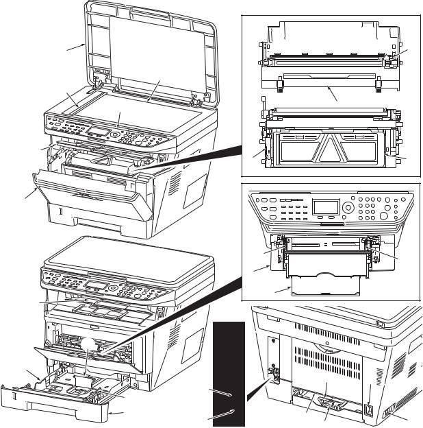
1-1-2 Parts names
(1) Overall
1 |
7 |
2 |
|
3 |
|
4 |
8 |
|
|
5 |
|
9 |
10 |
6 |
|
|
16 |
|
16 |
17 |
|
|
18 |
11 |
|
|
13 |
|
|
|
|
|
|
|
14 |
|
|
|
|
|
|
|
|
|
|
|
13 |
23 |
|
|
|
|
20 |
|
|
|
|
|
|
|
|
|
|
|
|
|
|
14 |
|
|
|
|
|
|
|
15 |
|
21 |
|
|
|
|
|
|
19 |
|
|
22 |
|
|
|
|
|
12 |
|
||
|
|
|
|
|
|
|
|
|
|
|
Figure 1-1-1 |
|
|
|
|
1. |
Original cover |
9. |
Lock lever |
17. |
MP (Multi-Purpose) tray |
|
|
2. |
Platen (contact glass) |
10. |
Toner container |
18. |
MP tray extension |
|
|
3. |
Original size Indicator plate |
11. |
Top tray |
19. |
USB Interface connector |
|
|
4. |
Operation panel |
12. |
Paper length guide |
20. |
Network Interface connector |
||
5. |
Top cover |
13. |
Paper stopper |
21. |
Rear cover |
|
|
6. |
Front cover |
14. |
Paper width guides |
22. |
Main power switch |
|
|
7. |
Main charger cleaner |
15. |
Cassette |
23. |
Power cord connector |
|
|
8. |
Drum unit |
16. |
Paper width guides (MP tray) |
|
|
|
|
1-1-3
2H9-1
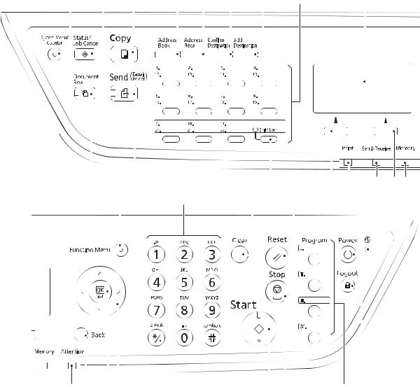
(2) Operation panel
1 |
|
2 |
3 |
|
|
4 |
5 |
6 |
7 |
|
8 |
9 |
|||||||||
|
|
|
|
|
|
|
|
|
|
|
|
|
|
|
|
|
|
|
|
|
|
|
|
|
|
|
|
|
|
|
|
|
|
|
|
|
|
|
|
|
|
|
|
|
|
|
|
|
|
|
|
|
|
|
|
|
|
|
|
|
|
|
|
|
|
|
|
|
|
|
|
|
|
|
|
|
|
|
|
|
|
|
|
|
|
|
|
|
|
|
|
|
|
|
|
|
|
|
|
|
|
|
|
|
|
|
|
|
|
|
|
|
|
|
|
|
|
|
|
|
|
|
|
|
|
|
|
|
|
|
|
|
|
|
|
|
|
|
|
|
|
|
|
|
|
|
|
|
|
|
|
|
|
|
|
|
|
|
|
|
|
|
|
|
|
|
|
|
|
|
|
|
|
|
|
|
|
|
|
|
|
|
|
|
|
|
|
|
|
|
|
|
|
|
|
|
|
|
|
|
|
|
|
|
|
|
|
|
|
|
|
|
|
|
|
|
|
|
|
|
|
|
|
|
|
|
|
|
|
|
|
|
|
|
|
|
|
|
|
|
|
|
|
|
|
|
|
|
|
|
|
|
|
|
|
|
|
|
|
|
|
|
|
|
|
|
|
|
|
|
|
|
|
|
|
|
|
|
|
|
|
|
|
|
|
|
|
|
|
|
|
|
|
|
|
|
|
|
|
|
|
|
|
|
|
|
|
10 |
|
|
|
11 |
|
|
|
|
|
|
12 |
|
|
13 |
14 |
|
|
|
15 |
16 |
17 |
|||
18 |
19 |
20 |
21 |
|
22 |
23 |
|
|
||||||||||||||||
|
|
|
|
|
|
|
|
|
|
|
|
|
|
|
|
|
|
|
|
|
|
|
|
|
|
|
|
|
|
|
|
|
|
|
|
|
|
|
|
|
|
|
|
|
|
|
|
|
|
|
|
|
|
|
|
|
|
|
|
|
|
|
|
|
|
|
|
|
|
|
|
|
|
|
|
|
|
|
|
|
|
|
|
|
|
|
|
|
|
|
|
|
|
|
|
|
|
|
|
|
|
|
|
|
|
|
|
|
|
|
|
|
|
|
|
|
|
|
|
|
|
|
|
|
|
|
|
|
|
|
|
|
|
|
|
|
|
|
|
|
|
|
|
|
|
|
|
|
|
|
|
|
|
|
|
|
|
|
|
|
|
|
|
|
|
|
|
|
|
|
|
|
|
|
|
|
|
|
|
|
|
|
|
|
|
|
|
|
|
|
|
|
|
|
|
|
|
|
|
|
|
|
|
|
|
|
|
|
|
|
|
|
|
|
|
|
|
|
|
|
|
|
|
|
|
|
|
|
|
|
|
|
|
|
|
|
|
|
|
|
|
|
|
|
|
|
|
|
|
|
|
|
|
|
|
|
|
|
|
|
|
|
|
|
|
|
|
|
|
|
|
|
|
|
|
|
|
|
|
|
|
|
|
|
|
|
|
|
|
|
|
|
|
|
|
|
|
|
|
|
|
|
|
|
|
|
|
|
|
|
|
|
|
|
|
|
|
|
|
|
|
|
|
|
|
|
|
|
|
|
|
|
|
|
|
|
|
|
|
|
|
|
|
|
|
|
|
|
|
|
|
|
|
|
|
|
|
|
|
|
|
|
|
|
|
|
|
|
|
|
|
|
|
|
|
24 |
25 |
26 27 |
|
28 |
29 |
|
30 |
31 |
|
|
|
|
|
Figure 1-1-2 |
|
|
|
|
1. |
System menu/Counter key |
11. |
Send key (LED) |
|
22. |
Power key |
|
||
|
(LED) |
|
|
12. |
Shift Lock key (LED) |
|
23. |
Main power indicator |
|
2. |
Status/Job Cancel key (LED) |
13. |
Left Select key |
|
24. |
Attention indicator |
|||
3. |
Copy key (LED) |
|
|
14. |
Print indicator |
|
25. |
Back key |
|
4. |
Address Book key |
|
|
15. |
Send/Receive indicator |
|
26. |
OK key |
|
5. |
Address Recall key |
|
|
16. |
Right Select key |
|
27. |
Cursor keys |
|
6. |
Confirm Destination key |
|
17. |
Memory indicator |
|
28. |
Start key (LED) |
||
7. |
Add Destination key |
|
18. |
Function Menu key (LED) |
|
29. |
Stop key |
|
|
8. |
One-touch keys |
|
|
19. |
Numeric keys |
|
30. |
Program keys |
|
9. |
Message display |
|
|
20. |
Clear key |
|
31. |
Logout key (LED) |
|
10. |
Document Box key (LED) |
21. |
Reset key |
|
|
|
|
||
1-1-4

2H9
1-1-3 Machine cross section
14
13
Paper path
|
|
|
|
Paper path |
|
|
|
|
(option) |
8 |
7 |
6 |
5 |
4 |
11 |
|
|
|
Light path |
10
2
|
12 |
9 |
1 |
3 |
|
|
Figure 1-1-3 |
|
|
1. |
Cassette |
|
8. |
Laser scanner unit (LSU) |
2. |
MP tray |
|
9. |
Transfer/separation section |
3. |
Paper feed/conveying section |
10. |
Fuser section |
|
4. |
Toner container |
|
11. |
Exit section |
5. |
Developing unit |
|
12. |
Duplex/conveying section |
6. |
Main charger unit |
|
13. |
Scanner section |
7. |
Drum unit |
|
14. |
Image scanner unit (ISU) |
1-1-5

2H9
This page is intentionally left blank.
1-1-6
2H9
1-2-1 Installation environment
1.Temperature: 10 to 32.5°C/50 to 90.5°F
2.Humidity: 15 to 80%RH
3.Power supply:120 V AC, 7.8 A
220 - 240 V AC, 4.0 A
4.Power source frequency: 50 Hz ±0.3%/60 Hz ±0.3%
5.Installation location
Avoid direct sunlight or bright lighting. Ensure that the photoconductor will not be exposed to direct sunlight or other strong light when removing paper jams.
Avoid locations subject to high temperature and high humidity or low temperature and low humidity; an abrupt change in the environmental temperature; and cool or hot, direct air.
Avoid places subject to dust and vibrations.
Choose a surface capable of supporting the weight of the machine.
Place the machine on a level surface (maximum allowance inclination: 1°).
Avoid air-borne substances that may adversely affect the machine or degrade the photoconductor, such as mercury, acidic of alkaline vapors, inorganic gasses, NOx, SOx gases and chlorine-based organic solvents.
Select a well-ventilated location.
6.Allow sufficient access for proper operation and maintenance of the machine.
500 mm
19 11/16"
300 mm |
300 mm |
300 mm |
1000 mm |
11 13/16" |
11 13/16" |
11 13/16" |
39 3/8" |
Figure 1-2-1
1-2-1

2H9-1
1-2-2 Unpacking
(1) Unpacking
|
13 |
17 |
16 |
|
|
120 V AC model |
|
23 |
|
18 |
14 |
20 |
|
21 |
|
22 |
6 |
|
|
|
15 |
220-240 V AC model |
|
18 |
|
19 |
|
|
9 |
|
|
11 |
10 |
12 |
|
|
|
8 |
|
|
|
3
7
2
4
 1
1
5
|
|
|
Figure 1-2-2 |
|
|
1. |
Printer |
10. |
Toner container |
19. |
EEA information leaflet** |
2. |
Outer case |
11. |
Plastic bag |
20. |
Setup guide* |
3. |
Inner frame |
12. |
Power cord |
21. |
Quick guide* |
4. |
Bottom pad L |
13. |
Plastic bag (250 × 600) |
22. |
Operation guide* |
5. |
Bottom pad R |
14. |
Operation labels |
23. |
CD-ROMs* |
6. |
Machine cover |
15. |
Operation label pad |
|
|
7. |
Top pad L |
16. |
Plastic bag (240 × 350) |
|
|
8. |
Top pad R |
17. |
Operation guide holder |
|
* 120 V AC model only. |
9. |
Accessory spacer |
18. |
Operation panel leaflet |
|
** 220-240 V AC model only. |
1-2-2
2H9
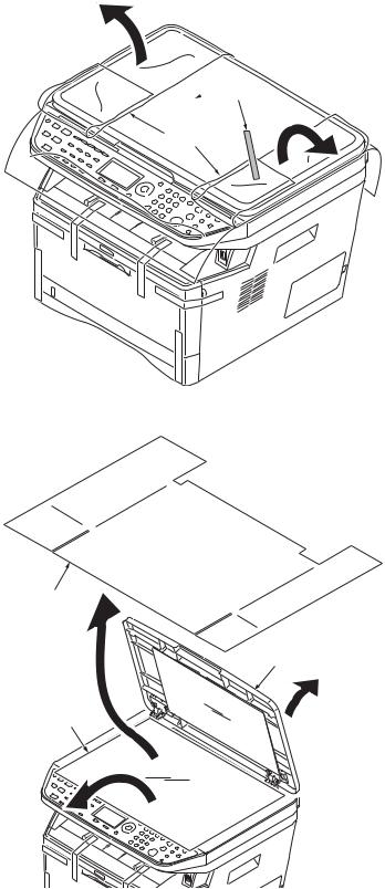
(2) Removing the tapes
<Procedure>
1.Remove two tapes.
2.Open the sheet.
 Tapes
Tapes
Sheet
Figure 1-2-3
3.Open the original cover.
4.Remove the sheet.
5.Remove the paper.
Sheet
Original cover
Paper
Figure 1-2-4
1-2-3
2H9
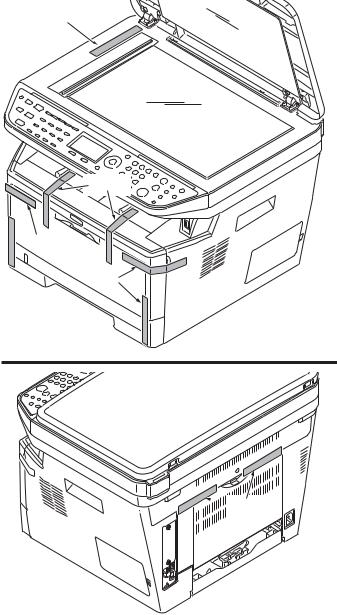
6. Remove nine tapes.
Tape
Tapes
 Tapes
Tapes
Tapes
 Tapes
Tapes
Figure 1-2-5
1-2-4
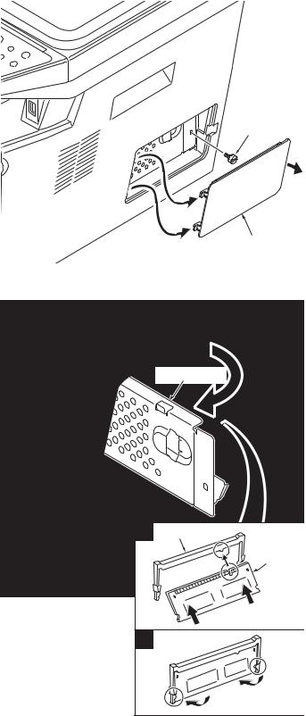
1-2-3 Installing the expansion memory (option)
<Procedure>
1.Turn off the main power switch.
Caution: Do not insert or remove expansion memory while machine power is on.
Doing so may cause damage to the machine and the expansion memory.
2.Remove the right side cover.
3.Remove the screw.
4.Open the memory slot cover.
5.Insert the expansion memory into the memory socket so that the notches on the memory align with the corresponding protrusions in the slot.
6.Close the memory slot cover.
7.Secure the screw.
8.Refit the right side cover.
9.Print a status page to check the memory expansion.
If memory expansion has been properly performed, information on the installed memory is printed with the total memory capacity has been increased. Standard memory capacity 256 MB.
2H9
Screw
Right side cover
Figure 1-2-6
Memory slot cover
1 Memory socket
Expansion memory
2
Figure 1-2-7
1-2-5

2H9
This page is intentionally left blank.
1-2-6
2H9-1
1-3-1 Maintenance mode
The machine is equipped with a maintenance function which can be used to maintain and service the machine.
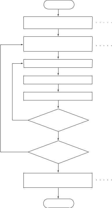
(1) Executing a maintenance item
Start
Enter “10871087” using the numeric keys.
Enter the maintenance item number using the cursor left/right keys
or numeric keys.
Press the start key.
The selected maintenance item is run.
Press the stop key.
Yes |
Repeat the same |
|
|
|
maintenance item? |
|
No |
Yes |
Run another maintenance |
|
|
|
item? |
|
No |
|
Enter “001” using the cursor |
|
left/right keys or numeric keys |
|
and press the start key. |
Maintenance mode is entered.
The maintenance item is selected.
Maintenance mode is exited.
End
1-3-1
2H9-1
(2) Maintenance modes item list
Section |
Item |
Content of maintenance item |
Initial |
|
|
No. |
|
setting* |
|
|
|
|
|
|
General |
U000 |
Outputting an own-status report |
- |
|
|
|
|
|
|
|
U001 |
Exiting the maintenance mode |
- |
|
|
|
|
|
|
|
U002 |
Setting the factory default data |
- |
|
|
|
|
|
|
|
U004 |
Displaying the machine number |
- |
|
|
|
|
|
|
|
U019 |
Displaying the ROM version |
- |
|
|
|
|
|
|
Initialization |
U021 |
Initializing counters and mode settings |
- |
|
|
|
|
|
|
Drive, paper |
U030 |
Checking motor operation |
- |
|
feed, paper |
|
|
|
|
U031 |
Checking switch/sensor for paper conveying |
- |
||
conveying |
||||
|
|
|
||
U032 |
Checking clutch operation |
- |
||
and cooling |
||||
system |
U033 |
Checking solenoid operation |
- |
|
|
|
|
|
|
|
U034 |
Adjusting the print start timing |
|
|
|
|
Adjusting the leading edge registration |
541/0/0/0 |
|
|
|
Adjusting the center line |
235/0/0/0/0/0/0 |
|
|
|
|
|
|
|
U051 |
Adjusting the deflection in the paper |
0/0/0/0/0 |
|
|
|
|
|
|
|
U053 |
Setting the adjustment of the motor speed |
0 |
|
|
|
|
|
|
Optical |
U063 |
Adjusting the shading position |
0 |
|
|
|
|
|
|
|
U065 |
Adjusting the scanner magnification |
|
|
|
|
Main scanning direction/auxiliary scanning direction |
0/0 |
|
|
|
|
|
|
|
U066 |
Adjusting the scanner leading edge registration |
0/0 |
|
|
|
|
|
|
|
U067 |
Adjusting the scanner center line |
0/0 |
|
|
|
|
|
|
|
U068 |
Adjusting the scanning position for originals from the DP |
0/0 |
|
|
|
|
|
|
|
U070 |
Adjusting the DP magnification |
0 |
|
|
|
|
|
|
|
U071 |
Adjusting the DP scanning timing |
0/0/0/0/0 |
|
|
|
|
|
|
|
U072 |
Adjusting the DP center line |
0/0 |
|
|
|
|
|
|
|
U073 |
Checking scanner operation |
- |
|
|
|
|
|
|
|
U087 |
Setting DP reading position modification operation |
125/125/120 |
|
|
|
|
|
|
|
U089 |
Outputting a MIP-PG pattern |
- |
|
|
|
|
|
|
High voltage |
U100 |
Setting the main high voltage |
0 |
|
|
|
|
|
|
|
U101 |
Setting the voltage for the primary transfer |
0 |
|
|
|
|
|
|
|
U111 |
Checking/clearing the drum drive time |
- |
|
|
|
|
|
|
|
U113 |
Performing drum refresh operation |
OFF/0 |
|
|
|
|
|
|
Developing |
U130 |
Initial setting for the developing unit |
- |
|
|
|
|
|
|
|
U144 |
Setting toner loading operation |
1/3/8/20/1/2/3 |
|
|
|
|
|
|
|
U157 |
Checking the developing drive time |
- |
|
|
|
|
|
|
Fuser and |
U161 |
Setting the fuser control temperature |
0/0/0/0/0/0/0 |
|
cleaning |
|
|
|
|
U199 |
Checking the fuser temperature |
- |
||
|
||||
|
|
|
|
*: Factory initial setting, *1: The item initialized for executing U021
1-3-2
2H9-2
Section |
Item |
Content of maintenance item |
Initial |
|
|
No. |
|
setting* |
|
|
|
|
|
|
Operation |
U200 |
Turning all LEDs on |
- |
|
panel and |
|
|
|
|
U203 |
Checking DP operation |
- |
||
support |
||||
|
|
|
||
U207 |
Checking the operation panel keys |
- |
||
equipment |
||||
|
|
|
||
|
U222 |
Setting the IC card type |
- |
|
|
|
|
|
|
|
U223 |
Operation panel lock |
- |
|
|
|
|
|
|
|
U243 |
Checking the operation of the DP motor solenoids and clutch |
- |
|
|
|
|
|
|
|
U244 |
Checking the DP sensors |
- |
|
|
|
|
|
|
Mode setting |
U250 |
Setting the maintenance cycle |
100000*1 |
|
|
U251 |
Checking/clearing the maintenance count |
- |
|
|
|
|
|
|
|
U252 |
Setting the destination |
- |
|
|
|
|
|
|
|
U253 |
Switching between double and single counts |
Double count |
|
|
|
|
|
|
|
U260 |
Selecting the timing for copy counting |
EJECT*1 |
|
|
U265 |
Setting OEM purchaser code |
0 |
|
|
|
|
|
|
|
U278 |
Setting the delivery date |
- |
|
|
|
|
|
|
|
U285 |
Setting service status page |
ON |
|
|
|
|
|
|
|
U332 |
Setting the size conversion factor |
1.0*1 |
|
|
U342 |
Setting the ejection restriction |
ON*1 |
|
|
U343 |
Switching between duplex/simplex copy mode |
OFF*1 |
|
|
U345 |
Setting the value for maintenance due indication |
0*1 |
|
Image |
U402 |
Adjusting margins of image printing |
30/25/25/50/50 |
|
processing |
|
|
|
|
U403 |
Adjusting margins for scanning an original on the platen |
2.0/2.0/2.0/5.0 |
||
|
||||
|
|
|
|
|
|
U404 |
Adjusting margins for scanning an original from the DP |
3.0/2.5/3.0/4.0 |
|
|
|
|
|
|
|
U407 |
Adjusting the leading edge registration for memory image |
0 |
|
|
|
printing |
|
|
|
|
|
|
|
|
U411 |
Adjusting the scanner automatically |
- |
|
|
|
|
|
|
|
U425 |
Setting the target |
- |
|
|
|
|
|
|
Others |
U901 |
Checking copy counts by paper feed locations |
- |
|
|
|
|
|
|
|
U903 |
Checking/clearing the paper jam counts |
- |
|
|
|
|
|
|
|
U904 |
Checking/clearing the service call counts |
- |
|
|
|
|
|
|
|
U905 |
Checking/clearing counts by optional devices |
- |
|
|
|
|
|
|
|
U908 |
Checking the total counter value |
- |
|
|
|
|
|
|
|
U910 |
Clearing the black ratio data |
- |
|
|
|
|
|
|
|
U911 |
Checking/clearing copy counts by paper sizes |
- |
|
|
|
|
|
|
|
U917 |
Setting backup data reading/writing |
- |
|
|
|
|
|
|
|
U920 |
Checking the copy counts |
- |
|
|
|
|
|
|
|
U927 |
Clearing the all copy counts and machine life counts (one |
- |
|
|
|
time only) |
|
|
|
|
|
|
|
|
U928 |
Checking machine life counts |
- |
|
|
|
|
|
|
|
U942 |
Setting of deflection for feeding from DP |
0/0 |
|
|
|
|
|
|
|
U969 |
Checking of toner area code |
- |
|
|
|
|
|
|
|
U977 |
Data capture mode |
- |
|
|
|
|
|
|
|
U991 |
Checking the scanner count |
- |
|
|
|
|
|
|
|
U993 |
Outputting a VTC-PG pattern |
- |
|
|
|
|
|
*: Factory initial setting, *1: The item initialized for executing U021
1-3-3

2H9-2
(3) Contents of the maintenance mode items
Maintenance |
Description |
||||
item No. |
|||||
|
|
||||
|
|
|
|
|
|
U000 Outputting an own-status report |
|
|
|||
Description |
|
|
|||
Outputs lists of the current settings of the maintenance items and paper jam and service call occurrences. |
|||||
Outputs the event log. Also sends output data to the USB memory. |
|||||
Printing a report is disabled either when a job is remaining in the buffer or when [Pause All Print Jobs] is |
|||||
pressed to halt printing. |
|
|
|||
Purpose |
|
|
|||
To check the current setting of the maintenance items, or paper jam or service call occurrences. Before initial- |
|||||
izing or replacing the backup RAM, output a list of the current settings of the maintenance items to reenter the |
|||||
settings after initialization or replacement. |
|||||
Method |
|
|
|||
1. Press the start key. |
|
|
|||
2. Select the item to be output using the cursor up/down keys. |
|||||
|
|
|
|
|
|
|
Display |
|
Output list |
|
|
|
|
|
|
|
|
|
MAINTENANCE |
|
List of the current settings of the maintenance modes |
|
|
|
EVENT |
|
Outputs the event log |
|
|
|
ALL |
|
Outputs the all reports |
|
|
|
|
|
|
||
3. Press the start key. The interrupt print mode is entered and a list is output. |
|||||
|
When A4/Letter paper is available, a report of this size is output. If not, specify the paper feed location. |
||||
|
When output is complete, the screen for selecting an item is displayed. |
||||
Method: Send to the USB memory
1.Press the power key on the operation panel, and after verifying the main power indicator has gone off, switch off the main power switch.
2.Insert USB memory in USB memory slot.
3.Turn the main power switch on.
4.Enter the maintenance item.
5.Press the start key.
6.Select the item to be send.
7.Select [TEXT] or [HTML].
Display |
Output list |
|
|
Outputs the report |
|
USB (TEXT) |
Sends output data to the USB memory (text type) |
USB (HTML) |
Sends output data to the USB memory (HTML type) |
|
|
8.Press the start key.
Output will be sent to the USB memory.
1-3-4
Loading...