


Engine Mechanical System
General Information
Engine Mechanical System

2009 > D 2.9 VGT >
SPECIFICATIONS
Description |
Specifications(J3 - ENG) |
Limit |
|
General |
|
|
|
|
|
|
|
Type |
|
In-line, DOHC |
|
|
|
|
|
Number of cylinders |
|
4 |
|
|
|
|
|
Bore |
|
101.5~101.526mm (3.9961~3.9971in) |
|
|
|
|
|
Stroke |
|
98mm (8.8583in) |
|
|
|
|
|
Total displacement |
|
2,902 cc (177.08 cu.in) |
|
|
|
|
|
Compression ratio |
|
18.4 : 1 |
|
|
|
|
|
Firing order |
|
1-3-4-2 |
|
|
|
|
|
Valve timing |
|
|
|
|
|
|
|
Intake valve |
Opens (ATDC) |
26° |
|
|
|
|
|
Closes (ABDC) |
50° |
|
|
|
|
||
|
|
|
|
Exhaust valve |
Opens (BBDC) |
72° |
|
|
|
|
|
Closes (ATDC) |
32° |
|
|
|
|
||
|
|
|
|
Cylinder head |
|
|
|
|
|
|
|
Flatness of gasket surface |
Less than 0.05mm (0.0020in) |
|
|
|
|
|
|
Flatness of manifold |
Intake |
Less than 0.15mm (0.0059in) |
|
mounting surface |
Exhaust |
Less than 0.15mm (0.0059in) |
|
|
|
|
|
Camshaft |
|
|
|
|
|
|
|
Cam height |
Intake |
39.397 ~ 39.597mm (1.5511 ~ 1.5589in) |
|
|
|
|
|
Exhaust |
39.4932 ~ 39.6932mm (1.5548 ~ 1.5627in) |
|
|
|
|
||
|
|
|
|
Journal outer Diameter (Intake, Exhaust) |
27.941 ~ 27.960mm (1.1000 ~ 1.1008in) |
|
|
|
|
|
|
Bearing oil clearance |
|
0.040 ~ 0.080mm (0.0016 ~ 0.0031in) |
|
|
|
|
|
End play |
|
0.08 ~ 0.17mm (0.0031 ~ 0.0067in) |
|
|
|
|
|
Valve |
|
|
|
|
|
|
|
Valve length |
Intake |
126.24mm (4.9701in) |
|
|
|
|
|
Exhaust |
126.24mm (4.9701in) |
|
|
|
|
||
|
|
|
|
Stem outer diameter |
Intake |
6.965 ~ 6.980mm (0.2742 ~ 0.2748in) |
|
|
|
|
|
Exhaust |
6.945 ~ 6.960mm (0.2734 ~ 0.2740in) |
|
|
|
|
||
|
|
|
|
Face angle |
|
45° |
|
|
|
|
|
Thickness of valve |
Intake |
1.7mm (0.0669in) |
|
head (margin) |
Exhaust |
1.6mm (0.0630in) |
|
|
|
|
|
Valve stem to valve |
Intake |
0.030 ~ 0.065mm (0.0012 ~ 0.0026in) |
|
guide clearance |
Exhaust |
0.050 ~ 0.085mm ( 0.0020~ 0.0033in) |
|
|
|
|
|
Valve guide |
|
|
|
|
|
|
|
Length |
Intake |
52.5mm (2.0669in) |
|
|
|
|
|
Exhaust |
52.5mm (2.0669in) |
|
|
|
|
||
|
|
|
|
Valve seat

Width of seat contact |
Intake |
1.4 ~ 2.0mm (0.0551 ~ 0.0787in) |
|
Exhaust |
0.9 ~ 1.5mm (0.0354 ~0.0591 in) |
|
|
|
|
||
|
|
|
|
Seat angle |
|
45° |
|
|
|
|
|
Valve spring |
|
|
|
|
|
|
|
Free length |
|
52.477mm (2.0660in) |
|
|
|
|
|
Load(Intake) |
Installed |
23.45±1.87kg/40.0mm(51.7±4.1lb/1.5748 in) |
|
|
|
|
|
Valve opened |
39.15±3.13kg/31.65mm(86.3±6.9 lb/1.2461 in) |
|
|
|
|
||
|
|
|
|
Load(Exhaust) |
Installed |
23.45±1.87kg/40.0mm(51.7±4.1lb/1.5748 in) |
|
|
|
|
|
Valve opened |
39.43±3.15kg/31.50mm(86.9±6.9 lb/1.2402 in) |
|
|
|
|
||
|
|
|
|
Out of squareness |
|
Less than 2° |
3° |
|
|
|
|
Rocker arm and rocker arm shaft |
|
|
|
|
|
|
|
Rocker arm inner diameter |
20.000 ~ 20.027mm (0.7874 ~ 0.7885in) |
|
|
|
|
|
|
Rocker arm shaft outer diameter |
19.959 ~ 19.980mm (0.7858 ~ 0.7866in) |
|
|
|
|
|
|
Cylinder block |
|
|
|
|
|
|
|
Cylinder bore |
|
101.500 ~ 101.526mm (3.9961 ~3.9971 in) |
|
|
|
|
|
Liner inner diameter |
|
97.100 ~ 97.126mm (3.8228~ 3.8239in) |
|
|
|
|
|
Liner outer diameter |
|
101.480 ~ 101.526mm ( 3.9953~ 3.9971in) |
|
|
|
|
|
Flatness of gasket surface |
Less than 0.05mm (0.0020in) |
|
|
|
|
|
|
Piston |
|
|
|
|
|
|
|
Piston outer diameter |
|
97.015 ~ 97.030mm ( 3.8195~ 3.8201in) |
|
|
|
|
|
Piston to cylinder clearance |
0.070 ~ 0.098mm (0.0028 ~ 0.0039in) |
|
|
|
|
|
|
|
No. 1 ring groove |
2.397 ~ 2.417mm ( 0.0944~0.0952 in) |
|
|
|
|
|
Ring groove width |
No. 2 ring groove |
2.05 ~ 2.07mm ( 0.0807~ 0.0815in) |
|
|
|
|
|
|
Oil ring groove |
3.02 ~ 3.04mm (0.1189 ~ 0.1197in) |
|
|
|
|
|
Piston ring |
|
|
|
|
|
|
|
|
|
|
|
Side clearance |
No. 2 ring |
0.06 ~ 0.10mm (0.0024~0.0039 in) |
|
|
|
|
|
|
Oil ring |
0.03 ~ 0.07mm (0.0012~0.0028 in) |
|
|
|
|
|
|
No. 1 ring |
0.25 ~ 0.40mm (0.0098~ 0.0157in) |
|
|
|
|
|
End gap |
No. 2 ring |
0.40 ~ 0.55mm (0.0157~0.0217in) |
|
|
|
|
|
|
Oil ring |
0.20 ~ 0.40mm (0.0079 ~ 0.0157in) |
|
|
|
|
|
Piston pin |
|
|
|
|
|
|
|
Piston pin outer diameter |
31.994 ~ 32.000mm (1.2596 ~ 1.2598 in) |
|
|
|
|
|
|
Piston pin hole inner diameter |
32.015 ~ 32.025mm (1.2604 ~ 1.2608 in) |
|
|
|
|
|
|
Piston pin hole clearance |
0.015 ~ 0.031mm (0.0006 ~ 0.0012 in) |
|
|
|
|
|
|
Connecting rod small end inner diameter |
32.012 ~ 32.033mm (1.2603 ~ 1.2611 in) |
|
|
|
|
|
|
Connecting rod small end hole clearance |
0.012 ~ -0.039mm (0.0005 ~ 0.0015 in) |
|
|
|
|
|
|
Connecting rod |
|
|
|
|
|
|
|
Connecting rod big end inner diameter |
60.833 ~ 60.846mm (2.3950 ~ 2.3955 in) |
|
|
|
|
|
|
Connecting rod bearing oil clearance |
0.043 ~ 0.077mm (0.0017 ~ 0.0030 in) |
|
|
|
|
|
|
End play |
|
0.239~0.39 (0.0094 ~ 0.0154 in) |
|
|
|
|
|

Crankshaft |
|
|
|
|
|
|
|
|
|
|
|
|
|
|
|
|
|
|
|
|
|
Main journal outer |
|
NO 1, 2, 4, 5 |
69.995 ~ 70.015mm (2.7557 ~2.7565 in) |
|
|
|||||
diameter |
|
NO 3 |
69.973~69.993mm (2.7548 ~2.7556 in) |
|
|
|||||
|
|
|
|
|
|
|
|
|
||
Pin journal outer diameter |
57.106~57.124mm (2.2483~2.2490 in) |
|
|
|||||||
|
|
|
|
|
|
|
|
|
|
|
Main bearing oil |
|
NO 1, 2, 4, 5 |
0.045 ~ 0.079mm (0.0018 ~0.0031 in) |
|
|
|||||
clearance |
|
NO 3 |
0.067~0.101 mm (0.0026 ~0.0040 in) |
|
|
|||||
|
|
|
|
|
|
|
|
|
|
|
End play |
|
|
0.14 ~ 0.39mm (0.0055 ~0.0154 in) |
|
|
|||||
|
|
|
|
|
|
|
|
|
|
|
Flywheel |
|
|
|
|
|
|
|
|
|
|
|
|
|
|
|
|
|
|
|
|
|
Runout |
|
|
0.10mm (0.0039in) |
|
0.13mm (0.0051in) |
|||||
|
|
|
|
|
|
|
|
|
|
|
Oil pump |
|
|
|
|
|
|
|
|
|
|
|
|
|
|
|
|
|
|
|||
Relief valve opening pressure |
588.40±49.0kpa(6.0±0.5kg/cm!,85.34±7.1psi) |
|
|
|||||||
|
|
|
|
|
|
|
|
|
|
|
Discharge volume |
|
|
75L/min(79.25 US qt/min, 65.99 lmp qt/min) |
|
|
|||||
|
|
(engine3,800rpm) |
|
|
|
|||||
|
|
|
|
|
|
|||||
|
|
|
|
|
|
|
|
|
|
|
Engine oil |
|
|
|
|
|
|
|
|
|
|
|
|
|
|
|
|
|
|
|
|
|
Oil quantity (Total) |
|
|
8.0 L (8.45 US qt, 7.03 lmp qt) |
|
|
|||||
|
|
|
|
|
|
|
|
|
|
|
Oil quantity (Oil pan) |
|
|
6.0 L (6.34 US qt, 5.27 lmp qt) |
|
|
|||||
|
|
|
|
|
|
|
|
|||
Oil quantity (Drain and refill including oil filter) |
6.6 L (6.97 US qt, 5.08 lmp qt) |
|
|
|||||||
|
|
|
|
|
|
|
|
|
|
|
Oil quality |
|
|
ABOVE API CH-4 or ABOVE ACEA B4 |
|
|
|||||
|
|
|
|
|
|
|
|
|
|
|
Oil pressure (Idle) |
|
|
78.45 kpa (0.8 kg/cm!, 11.38 psi) |
|
|
|||||
|
|
|
|
|
|
|
|
|
|
|
Cooling system |
|
|
|
|
|
|
|
|
|
|
|
|
|
|
|
|
|
|
|
|
|
Cooling method |
|
|
Forced circulation with cooling fan |
|
|
|||||
|
|
|
|
|
|
|
|
|
|
|
|
|
Type |
Wax pellet type |
|
|
|
||||
|
|
|
|
|
|
|
|
|
|
|
Thermostat |
|
Opening temperature |
88±1.5 °C (190.4 ±34.7 °F) |
|
|
|
||||
|
|
|
|
|
|
|
|
|
|
|
|
Pull opening |
100 °C (212.0 °F) |
|
|
|
|||||
|
|
|
|
|
||||||
|
|
temperature |
|
|
|
|||||
|
|
|
|
|
|
|
|
|
|
|
|
|
|
|
|
|
|
|
|
|
|
Radiator cap |
|
Main valve opening |
93.16 ~ 122.58kpa(0.95 ~ 1.25kg/cm!, 13.51 |
|
|
|||||
|
pressure |
~ 17.78psi) |
|
|
|
|
||||
|
|
|
|
|
|
|||||
|
|
|
|
|
|
|
|
|
|
|
Water temperature sensor |
|
|
|
|
|
|
|
|
||
|
|
|
|
|
|
|
|
|
|
|
Type |
|
|
Thermister type |
|
|
|
||||
|
|
|
|
|
|
|
|
|
|
|
Resistance |
|
20°C (68°F) |
2.27~2.64 k" |
|
|
|
|
|||
|
|
|
|
|
|
|
|
|
|
|
|
80°C (176°F) |
0.31~0.33 k" |
|
|
|
|
||||
|
|
|
|
|
|
|||||
|
|
|
|
|
|
|
|
|
|
|
TIGHTENING TORQUE |
|
|
|
|
|
|
|
|
||
|
|
|
|
|
|
|
|
|
|
|
|
Item |
|
|
Quan- |
|
|
Tightening torque |
|||
|
|
|
tity |
|
N.m |
kgf.m |
|
lb-ft |
||
|
|
|
|
|
|
|
||||
Cylinder block |
|
|
|
|
|
|
|
|
|
|
|
|
|
|
|
|
|
|
|||
Engine support bracket bolts |
|
8 |
|
36.3 ~ 53.9 |
3.7 ~ 5.5 |
|
26.8 ~ 39.8 |
|||
|
|
|
|
|
|
|
|
|
|
|
Engine mounting |
|
|
|
|
|
|
|
|
|
|
|
|
|
|
|
|
|
|
|||
Engine mounting insulator and engine mounting |
4 |
|
36.3 ~ 53.9 |
3.7 ~ 5.5 |
|
26.8 ~ 39.8 |
||||
bracket fixing nuts |
|
|
|
|
|
|||||
|
|
|
|
|
|
|
|
|
|
|
|
|
|
|
|
|
|
|
|
||
Engine support bracket and engine mounting |
|
2 |
|
36.3 ~ 53.9 |
3.7 ~ 5.5 |
|
26.8 ~ 39.8 |
|||
insulator fixing nuts |
|
|
|
|
|
|||||
|
|
|
|
|
|
|
|
|
|
|
|
|
|
|
|
|
|
|
|
|
|
Transaxle mounting bracket and body fixing |
4 |
36.3 |
~ 53.9 |
3.7 |
~ 5.5 |
26.8 |
~ 39.8 |
||
bolts |
|||||||||
|
|
|
|
|
|
|
|
||
|
|
|
|
|
|
|
|
|
|
Transaxle mounting insulator and transaxle |
1 |
62.8 |
~ 93.2 |
6.4 |
~ 9.5 |
46.3 |
~ 68.7 |
||
mounting bracket fixing bolt |
|||||||||
|
|
|
|
|
|
|
|
||
|
|
|
|
|
|
|
|
|
|
Transaxle and transaxle mounting insulator |
4 |
36.3 |
~ 53.9 |
3.7 |
~ 5.5 |
26.8 |
~ 39.8 |
||
fixing nuts |
|||||||||
|
|
|
|
|
|
|
|
||
|
|
|
|
|
|
|
|
|
|
Main moving system |
|
|
|
|
|
|
|
|
|
|
|
|
|
|
|
||||
Connecting rod cap nuts |
8 |
68.6#Unfasten |
7.0 # Unfasten |
50.6# Unfasten |
|||||
bolts#29.4+90° |
bolts#3.0+ 90° |
bolts#21.7+ 90° |
|||||||
|
|
|
|||||||
|
|
|
|
|
|
||||
Crankshaft main bearing cap bolts |
10 |
(63.7 ~ 73.5) + |
(6.5 ~ 7.5) + (105 |
(47.0 ~ 54.2) + |
|||||
(105 + 115°) |
+ 115°) |
(105 + 115°) |
|||||||
|
|
|
|||||||
|
|
|
|
|
|
|
|
|
|
Flywheel (DMF) bolts (M/T) |
8 |
122.6 |
~ 132.4 |
12.5 |
~ 13.5 |
90.4 |
~ 97.6 |
||
|
|
|
|
|
|
|
|
|
|
Drive plate bolts (A/T) |
8 |
159.8 |
~ 169.7 |
16.3 |
~ 17.3 |
117.9 |
~ 125.1 |
||
|
|
|
|
|
|
|
|
|
|
Timing belt |
|
|
|
|
|
|
|
|
|
|
|
|
|
|
|
|
|
|
|
Timing belt upper cover bolts |
5 |
6.9 |
~ 9.8 |
0.7 |
~ 1.0 |
5.1 |
~ 7.2 |
||
|
|
|
|
|
|
|
|
|
|
Timing belt upper cover nut |
1 |
6.9 |
~ 9.8 |
0.7 |
~ 1.0 |
5.1 |
~ 7.2 |
||
|
|
|
|
|
|
|
|
|
|
Timing belt lower cover bolts |
8 |
6.9 |
~ 9.8 |
0.7 |
~ 1.0 |
5.1 |
~ 7.2 |
||
|
|
|
|
|
|
|
|
|
|
Crankshaft pulley bolt |
1 |
372.7 |
~ 411.9 |
38.0 |
~ 42.0 |
274.9 |
~ 303.8 |
||
|
|
|
|
|
|
|
|
|
|
Camshaft sprocket bolts |
2 |
58.8 |
~ 68.6 |
6.0 |
~ 7.0 |
43.4 |
~ 50.6 |
||
|
|
|
|
|
|
|
|
|
|
Timing belt tensioner bolt |
1 |
20.6 |
~ 25.5 |
2.1 |
~ 2.6 |
15.2 |
~ 18.8 |
||
|
|
|
|
|
|
|
|
|
|
Timing belt N0. 1 idler bolt |
1 |
39.2 |
~ 49.0 |
4.0 |
~ 5.0 |
28.9 |
~ 36.2 |
||
|
|
|
|
|
|
|
|
|
|
Timing belt N0. 2 idler bolt |
1 |
37.3 |
~ 43.1 |
3.8 |
~ 4.4 |
27.5 |
~ 31.8 |
||
|
|
|
|
|
|
|
|
|
|
Touch idler bolt |
1 |
20.6 |
~ 25.5 |
2.1 |
~ 2.6 |
15.2 |
~ 18.8 |
||
|
|
|
|
|
|
|
|
|
|
High pressure pump puli nut |
1 |
58.8 |
~ 68.6 |
6.0 |
~ 7.0 |
43.4 |
~ 50.6 |
||
|
|
|
|
|
|
|
|
|
|
High pressure pump and Timing belt case fixing |
3 |
21.6 |
~ 25.5 |
2.2 |
~ 2.6 |
15.9 |
~ 18.8 |
||
bolts |
|||||||||
|
|
|
|
|
|
|
|
||
|
|
|
|
|
|
|
|
|
|
High pressure pump bracket bolts (Pump) |
2 |
21.6 |
~ 25.5 |
2.2 |
~ 2.6 |
15.9 |
~ 18.8 |
||
|
|
|
|
|
|
|
|
|
|
High pressure pump bracket bolts (Cylinder |
2 |
34.3 |
~ 40.2 |
3.5 |
~ 4.1 |
25.3 |
~ 29.7 |
||
block) |
|||||||||
|
|
|
|
|
|
|
|
||
|
|
|
|
|
|
|
|
||
Timing belt plate bolts |
6 |
7.8 ~ 11.8 |
0.8 |
~ 1.2 |
5.8 |
~ 8.7 |
|||
|
|
|
|
|
|
|
|
|
|
Timing belt case bolts (8 X 25) |
8 |
15.7 |
~ 22.6 |
1.6 |
~ 2.3 |
11.6 |
~ 16.6 |
||
|
|
|
|
|
|
|
|
|
|
Timing belt case bolts (8 X 45) |
2 |
15.7 |
~ 22.6 |
1.6 |
~ 2.3 |
11.6 |
~ 16.6 |
||
|
|
|
|
|
|
|
|
|
|
Timing belt case bolts (8 X 50) |
2 |
15.7 |
~ 22.6 |
1.6 |
~ 2.3 |
11.6 |
~ 16.6 |
||
|
|
|
|
|
|
|
|
|
|
Timing belt case nut |
1 |
15.7 |
~ 22.6 |
1.6 |
~ 2.3 |
11.6 |
~ 16.6 |
||
|
|
|
|
|
|
|
|
|
|
Balancer gear bolt |
1 |
63.7 |
~ 73.5 |
6.5 |
~ 7.5 |
47.0 |
~ 54.2 |
||
|
|
|
|
|
|
|
|
|
|
Oil pump gear bolt |
1 |
33.3 |
~ 39.2 |
3.4 |
~ 4.0 |
24.6 |
~ 28.9 |
||
|
|
|
|
|
|
|
|
|
|
Idler gear bolt |
1 |
33.3 |
~ 39.2 |
3.4 |
~ 4.0 |
24.6 |
~ 28.9 |
||
|
|
|
|
|
|
|
|
|
|
Cylinder head |
|
|
|
|
|
|
|
|
|
|
|
|
|
|
|
||||
Cylinder head cover bolts |
15 |
8.8 ~ -10.8 |
0.9 ~ -1.1 |
6.5 ~ -8.0 |
|||||
|
|
|
|
|
|
|
|
|
|
Rocker arm shaft And camshaft bearing cap |
10 |
17.7 |
~ 26.5 |
1.8 |
~ 2.7 |
13.0 |
~ 19.5 |
||
bolts |
|||||||||
|
|
|
|
|
|
|
|
||
|
|
|
|
|
|
|
|
|
|
Camshaft bearing cap nuts |
10 |
17.7 |
~ 26.5 |
1.8 |
~ 2.7 |
13.0 |
~ 19.5 |
||
|
|
|
|
|
|
|
|
||
Front camshaft bearing cap nuts(Small nuts) |
2 |
7.8 ~ 11.8 |
0.8 |
~ 1.2 |
5.8 |
~ 8.7 |
|||
|
|
|
|
|
|
|
|
|
|
Cylinder head bolt (Long bolts) |
10 |
39.2 + 90° + 120° |
4.0 + 90° + 120° |
28.9 + 90° + 120° |
|||||
Cylinder head bolt (Short bolts) |
8 |
39.2 + 90°+ 90° |
4.0 + 90° + 90° |
28.9 + 90°+ 90° |
|||||
|
|
|
|
|
|
|
|
|
|
Cooling system |
|
|
|
|
|
|
|
|
|
|
|
|
|
|
|
|
|
|
|
Cooling fan water pump pulley bolts |
4 |
5.9 |
~ 9.8 |
0.6 |
~ 1.0 |
4.3 |
~ 7.2 |
||
|
|
|
|
|
|
|
|
|
|
Water pump bolt (Long bolts) |
3 |
15.7 |
~ 22.6 |
1.6 |
~ 2.3 |
11.6 |
~ 16.6 |
||
|
|
|
|
|
|
|
|
|
|
Water pump bolt (Short bolts) |
2 |
15.7 |
~ 22.6 |
1.6 |
~ 2.3 |
11.6 |
~ 16.6 |
||
|
|
|
|
|
|
|
|
|
|
Water pump and generator brace fixing bolts (8 |
2 |
15.7 |
~ 22.6 |
1.6 |
~ 2.3 |
11.6 |
~ 16.6 |
||
X 45) |
|||||||||
|
|
|
|
|
|
|
|
||
|
|
|
|
|
|
|
|
|
|
Thermostat housing and generator strip nuts |
2 |
18.6 |
~ 22.6 |
1.9 |
~ 2.3 |
13.7 |
~ 16.6 |
||
|
|
|
|
|
|
|
|
|
|
Thermostat case cover bolts |
2 |
15.7 |
~ 22.6 |
1.6 |
~ 2.3 |
11.6 |
~ 16.6 |
||
|
|
|
|
|
|
|
|
|
|
Lubrication system |
|
|
|
|
|
|
|
|
|
|
|
|
|
|
|
|
|
|
|
Oil filter |
1 |
21.6 |
~ 24.5 |
2.2 |
~ 2.5 |
15.9 |
~ 18.1 |
||
|
|
|
|
|
|
|
|
|
|
Oil cooler bolts (8 X 35) |
4 |
15.7 |
~ 22.6 |
1.6 |
~ 2.3 |
11.6 |
~ 16.6 |
||
|
|
|
|
|
|
|
|
|
|
Oil cooler bolts (8 X 50) |
4 |
15.7 |
~ 22.6 |
1.6 |
~ 2.3 |
11.6 |
~ 16.6 |
||
|
|
|
|
|
|
|
|
|
|
Oil cooler nuts |
2 |
15.7 |
~ 22.6 |
1.6 |
~ 2.3 |
11.6 |
~ 16.6 |
||
|
|
|
|
|
|
|
|
|
|
Oil pan nuts |
29 |
15.7 |
~ 22.6 |
1.6 |
~ 2.3 |
11.6 |
~ 16.6 |
||
|
|
|
|
|
|
|
|
|
|
Oil pan drain plug |
1 |
34.3 |
~ 44.1 |
3.5 |
~ 4.5 |
25.3 |
~ 32.5 |
||
|
|
|
|
|
|
|
|
|
|
Ladder frame bolts (10 X 45) |
5 |
31.4 |
~ 46.1 |
3.2 |
~ 4.7 |
23.1 |
~ 34.0 |
||
|
|
|
|
|
|
|
|
|
|
Ladder frame and oil suppling pipe bolt (8X 50) |
1 |
15.7 |
~ 22.6 |
1.6 |
~ 2.3 |
11.6 |
~ 16.6 |
||
|
|
|
|
|
|
|
|
|
|
Ladder frame bracket (Oil pump and ladder |
2 |
31.4 |
~ 46.1 |
3.2 |
~ 4.7 |
23.1 |
~ 34.0 |
||
frame fixing) bolts |
|||||||||
|
|
|
|
|
|
|
|
||
|
|
|
|
|
|
|
|
|
|
Oil supplying pipe and oil pump fixing bolts (8 |
2 |
15.7 |
~ 22.6 |
1.6 |
~ 2.3 |
11.6 |
~ 16.6 |
||
X16) |
|||||||||
|
|
|
|
|
|
|
|
||
|
|
|
|
|
|
|
|
|
|
Oil supplying pipe and Ladder frame fixing bolts |
2 |
15.7 |
~ 22.6 |
1.6 |
~ 2.3 |
11.6 |
~ 16.6 |
||
(8 X 16) |
|||||||||
|
|
|
|
|
|
|
|
||
|
|
|
|
|
|
|
|
|
|
Oil pump bolts(10 X 60) |
2 |
15.7 |
~ 22.6 |
1.6 |
~ 2.3 |
11.6 |
~ 16.6 |
||
|
|
|
|
|
|
|
|
|
|
Oil pump bolt(8 X 30) |
1 |
15.7 |
~ 22.6 |
1.6 |
~ 2.3 |
11.6 |
~ 16.6 |
||
|
|
|
|
|
|
|
|
|
|
Oil screen nuts |
2 |
15.7 |
~ 22.6 |
1.6 |
~ 2.3 |
11.6 |
~ 16.6 |
||
|
|
|
|
|
|
|
|
|
|
Oil pressure switch |
1 |
14.7 |
~ 46.1 |
1.5 |
~ 2.2 |
10.8 |
~ 34.0 |
||
|
|
|
|
|
|
|
|
|
|
Intake and exhaust system |
|
|
|
|
|
|
|
|
|
|
|
|
|
|
|
|
|
|
|
Intake manifold and cylinder head fixing bolts(8 |
2 |
15.7 |
~ 22.6 |
1.6 |
~ 2.3 |
11.6 |
~ 16.6 |
||
X 45) |
|||||||||
|
|
|
|
|
|
|
|
||
|
|
|
|
|
|
|
|
|
|
Intake manifold and cylinder head fixing bolts(8 |
4 |
15.7 |
~ 22.6 |
1.6 |
~ 2.3 |
11.6 |
~ 16.6 |
||
X 95) |
|||||||||
|
|
|
|
|
|
|
|
||
|
|
|
|
|
|
|
|
|
|
Intake manifold and cylinder head fixing nuts |
2 |
15.7 |
~ 22.6 |
1.6 |
~ 2.3 |
11.6 |
~ 16.6 |
||
|
|
|
|
|
|
|
|
|
|
Intake manifold and cylinder head fixing |
1 |
17.7 |
~ 26.5 |
1.8 |
~ 2.7 |
13.0 |
~ 19.5 |
||
hexagonal wrench bolt |
|||||||||
|
|
|
|
|
|
|
|
||
|
|
|
|
|
|
|
|
|
|
Exhaust manifold and cylinder head fixing nut |
9 |
26.5 |
~ 34.3 |
2.7 |
~ 3.5 |
19.5 |
~ 25.3 |
||
|
|
|
|
|
|
|
|
|
|
Exhaust manifold heat cover and exhaust |
3 |
8.8 ~ 12.7 |
0.9 |
~ 1.3 |
6.5 |
~ 9.4 |
|||
manifold fixing bolts(6X12) |
|||||||||
|
|
|
|
|
|
|
|
||
|
|
|
|
|
|
|
|
|
|
Engine hanger bracket and exhaust manifold |
2 |
17.7 |
~ 26.5 |
1.8 |
~ 2.7 |
13.0 |
~ 19.5 |
||
fixing bolts (8 X 18) |
|||||||||
|
|
|
|
|
|
|
|
||
|
|
|
|
|
|
|
|
|
|
Exhaust manifold and front muffler fixing nut |
2 |
39.2 |
~ 58.8 |
4.0 |
~ 6.0 |
28.9 |
~ 43.4 |
||
|
|
|
|
|
|
|
|
|
|
Front muffler CPF(Catalyzed Particulate Filter) |
2 |
39.2 ~ 58.8 |
4.0 |
~ 6.0 |
28.9 ~ 43.4 |
|
fixing nuts |
||||||
|
|
|
|
|
||
|
|
|
|
|
|
|
CPF(Catalyzed Particulate Filter) main muffler |
2 |
39.2 ~ 58.8 |
4.0 |
~ 6.0 |
28.9 ~ 43.4 |
|
fixing nuts |
||||||
|
|
|
|
|
||
|
|
|
|
|
|
|
Main muffler and tail pipe fixing nuts |
2 |
39.2 ~ 58.8 |
4.0 |
~ 6.0 |
28.9 ~ 43.4 |
|
|
|
|
|
|
|
2009 > D 2.9 VGT >
INSPECTION
COMPESSION PRESSURE
If there is lack of power, excessive oil consumption or poor fuel economy, measure the compression pressure.
1.Warm up the engine until the coolant temperature becomes 80~95°C(176~203°F).
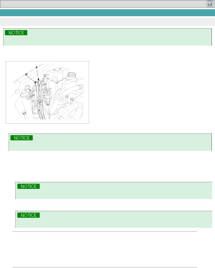
2.Remove the fuel inlet(A) and the return hose(B) from the fuel filter.
3. Crank the engine in order to exhaust fuel in the high pressure pump.
Gather residual fuel by putting the return hose into a proper vessel.
4.Remove the injection pipe, injector and washer.(Refer to FL group).
5.Measure the cylinder compression pressure.
(1)Insert the SST(0K552 131 002) into the injector hole.
(2)Cranking the engine, measure the pressure.
Use the complete charging battery for the engine to crank at the speed of 350rpm or more.
(3) Do the above step 1)~2) again for each cylinder.
This work must be done in as short time as possible.
Compression pressure :
3040.05kPa (31kg/cm!, 440.92psi) (325 rpm) Minimum pressure :
2745.85kPa (28kg/cm!, 398.25psi) Difference between each cylinder : 294.20kPa (3.0kg/cm!, 42.67psi)
(4)If, in one or more cylinders, the measured value is below the limit, fill a little engine oil into the injector holes of the cylinders, repeat the step 1)~2) and measure the compression pressure again.
A.If the re-measured pressure becomes higher, wear or damage of the piston ring or cylinder surface can be the cause.
B.If the re-measured pressure does not become higher, adherence or poor contact of the valves or inferior

gasket can be the cause.
6.Install the injectors, washers and the injector pipes.(Refer to FL group).
7.Install the inlet and the return hoses to the fuel filter.
TIMING BELT TENSION ADJUSTMENT
1. Remove the battery terminals (A).
2.Install the jack for oil pan.
3.Remove the engine mounting (A).
4. Remove the engine support bracket(A).
5. Remove the drive belt.
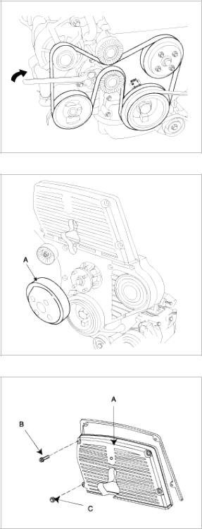
6. Remove the water pump pulley.
7. Remove the bolts(B), nut(C) and timing belt upper cover (A).
8.Turn the crankshaft pulley(A) and align its groove with the timing mark “T” of the timing belt cover. Check that the timing mark of camshaft sprocket(B) is aligned with that of the cylinder head cover. (No.1 cylinder positioned at the TDC position)
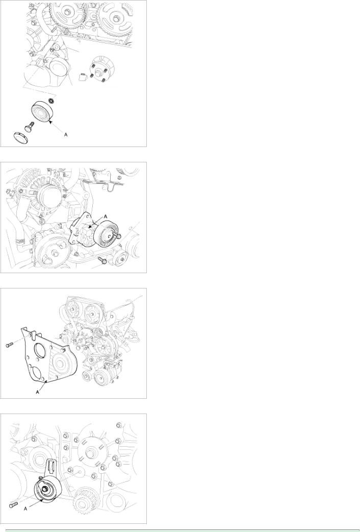
9. Remove the crankshaft pulley bolt(A), washer(B) and crankshaft pulley(C).
Using the special tool(09517-21700, 09231-H1000), fix the crankshaft pulley and loosen the bolt(A). 10. Remove the drive belt idler(A).
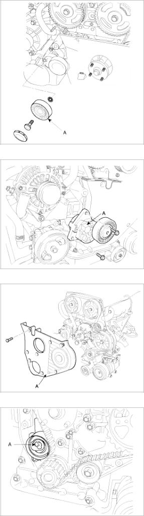
11. Remove the drive belt auto-tensioner (A).
12. Remove the timing belt lower cover(A).
13. Loosen the auto-tensioner fixing bolt(A).

14.Adjust tension of the timing belt.
(1)Align the pointer(B) with the tensioner fork(back plate)(C) as shown below by turning the special washer(A) counterclockwise with a hexagonal wrench.
(2)When the pointer(A) is aligned with the tensioner fork(back plate)(B), tighten the tensioner mounting bolts with the special bolt fixed by a hexagonal wrench.
Tightening torque :
19.6~25.5Nm (2.0~2.6kgf.m, 14.5~18.8lb-ft)
(3) Remove the hexagonal wrench.
When the pointer (A) can not be aligned with the tensioner fork(back plate)(B), replace a new belt and repeat the steps.
15.Rotate the crankshaft clockwise two revolutions in order to align the timing marks on the crankshaft sprocket, the camshaft sprocket and high pressure pump pulley.
16.Confirm that the location of the pointer is aligned with tensioner fork (back plate). The margin of error : ± 5°

17.Install the timing belt lower cover(A).
Tightening torque :
6.9~9.8Nm (0.7 ~ 1.0kgf.m, 5.1 ~ 7.2lb-ft)
18.Install the drive belt idler(A).
Tightening torque :
37.3Nm (3.8kgf.m, 27.5lb-ft)
19.Install the drive belt auto-tensioner (A).
Tightening torque :
15.7~22.6Nm (1.6 ~ 2.3kgf.m, 11.6 ~ 16.6lb-ft)

20.Install the crankshaft pulley bolt(A), washer(B) and crankshaft pulley (A).
Tightening torque :
376.6~411.9Nm (38.4~42.0kgf.m, 277.7~303.8lb-ft)
Using the special tool(09517-21700, 09231-H1000), tighten the bolt(A).
21.Install the bolts(B), nut(C) and timing belt upper cover (A).
Tightening torque :
6.9~9.8Nm (0.7 ~ 1.0kgf.m, 5.1 ~ 7.2lb-ft)
22.Install the water pump pulley.
Tightening torque :
5.9~9.8Nm (0.6 ~ 1.0kgf.m, 4.3 ~ 7.2lb-ft)

23. Install the drive belt.
24. Confirm that the 'A' part of the drivebelt auto-tensioner is positioned as shown below. If not, replace the belt.
25.Install the engine support bracket(A).
Tightening torque :
49.0~63.7Nm (5.0 ~ 6.5kgf.m, 36.2 ~ 47.0lb-ft)

26.Install the engine mounting (A).
Tightening torque :
88.3~107.9Nm (9.0 ~ 11.0kgf.m, 65.1 ~ 79.6lb-ft)
27.Remove the jack for oil pan.
28.Install the battery terminals (A).

2009 > D 2.9 VGT >
TROUBLESHOOTING
Symptom |
Suspect area |
Remedy |
|
Engine misfire with abnormal |
Loose or improperly installed engine |
Repair or replace the flywheel as |
|
internal lower engine noises. |
flywheel. |
required. |
|
|
|
|
|
|
Worn piston rings. |
Inspect the cylinder for a loss of |
|
|
(Oil consumption may or may not cause |
compression . |
|
|
the engine to misfire.) |
Repair or replace as required. |
|
|
|
|
|
|
Worn crankshaft thrust bearings. |
Replace the crankshaft and bearings as |
|
|
|
required. |
|
|
|
|
|
Engine misfire with abnormal |
Stuck valves. |
Repair or replace as required. |
|
valve train noise. |
(Carbon buildup on the valve stem can |
|
|
|
cause the valve not to close properly.) |
|
|
|
|
|
|
|
Excessive worn or mis-aligned timing |
Replace the timing chain and sprocket |
|
|
chain. |
as required. |
|
|
|
|
|
|
Worn camshaft lobes. |
Replace the camshaft and valve lifers. |
|
|
|
|
|
Engine misfire with coolant |
• Faulty cylinder head gasket and/or |
• Inspect the cylinder head and engine |
|
consumption |
cracking or other damage to the |
block for damage to the coolant |
|
|
cylinder head and engine block |
passages and/or a faulty head |
|
|
cooling system . |
gasket. |
|
|
• Coolant consumption may or may not |
• Repair or replace as required. |
|
|
cause the engine to overheat. |
|
|
|
|
|
|
Engine misfire with excessive |
Worn valves, valve guides and/or valve |
Repair or replace as required. |
|
oil consumption |
stem oil seals. |
|
|
|
|
|
|
|
Worn piston rings. |
Inspection the cylinder for a loss of |
|
|
(Oil consumption may or may not cause |
compression |
|
|
the engine to misfire) |
Repair or replace as required. |
|
|
|
|
|
Engine noise on start-up, but |
Incorrect oil viscosity. |
Drain the oil. |
|
only lasting a few seconds. |
|
Install the correct viscosity oil. |
|
|
|
|
|
|
Worn crankshaft thrust bearing. |
Inspect the thrust bearing and |
|
|
|
crankshaft. |
|
|
|
Repair or replace as required. |
|
|
|
|
|
Upper engine noise, regardless |
Low oil pressure. |
Repair or replace as required. |
|
of engine speed. |
|
|
|
Broken valve spring. |
Replace the valve spring. |
||
|
|||
|
|
|
|
|
Worn or dirty valve lifters. |
Replace the valve lifters. |
|
|
|
|
|
|
Stretched or broken timing chain and/or |
Replace the timing chain and sprockets. |
|
|
damaged sprocket teeth. |
|
|
|
|
|
|
|
Worn timing chain tensioner, if |
Replace the timing chain tensioner as |
|
|
applicable. |
required. |
|
|
|
|
|
|
Worn camshaft lobes. |
Inspect the camshaft lobes. |
|
|
|
Replace the camshaft and valve lifters as |
|
|
|
required. |
|
|
|
|
|
|
Worn valve guides or valve stems. |
Inspect the valves and valve guides, then |
|
|
|
repair as required. |
|
|
|
|
|
|
Stuck valves. (Carbon on the valve stem |
Inspect the valves and valve guides, then |
|
|
or valve seat may cause the valve to |
repair as required. |
|
|
stay open.) |
|
|
|
|
|
|
|
|
|
Lower engine noise, regardless |
Low oil pressure. |
Repair or replace damaged components |
of engine speed. |
|
as required. |
|
|
|
|
Loose or damaged flywheel. |
Repair or replace the flywheel. |
|
|
|
|
Damaged oil pan, contacting the oil |
Inspect the oil pan. |
|
pump screen. |
Inspect the oil pump screen. |
|
|
Repair or replace as required. |
|
|
|
|
Oil pump screen loose, damaged or |
Inspect the oil pump screen . |
|
restricted. |
Repair or replace as required. |
|
|
|
|
Excessive piston-to-cylinder bore |
Inspect the piston and cylinder bore. |
|
clearance. |
Repair as required. |
|
|
|
|
Excessive piston pin-to-bore clearance. |
Inspect the piston, piston pin and the |
|
|
connecting rod. |
|
|
Repair or replace as required. |
|
|
|
|
Excessive connecting rod bearing |
Inspect the following components and |
|
clearance. |
repair as required. |
|
|
• The connecting rod bearings. |
|
|
• The connecting rods. |
|
|
• The crankshaft. |
|
|
• The crankshaft journal. |
|
|
|
|
Excessive crankshaft bearing clearance. |
Inspect the following components and |
|
|
repair as required. |
|
|
• The crankshaft bearings. |
|
|
• The crankshaft journals. |
|
|
|
|
Incorrect piston, piston pin and |
Verify the piston pins and connecting |
|
connecting rod installation. |
rods are installed correctly. |
|
|
Repair as required. |
|
|
|
Engine noise under load. |
Low oil pressure. |
Repair or replace as required. |
|
|
|
|
Excessive connecting rod bearing |
Inspect the following components and |
|
clearance. |
repair as required. |
|
|
• The connecting rod bearings. |
|
|
• The connecting rods. |
|
|
• The crankshaft. |
|
|
|
|
Excessive crankshaft bearing clearance. |
Inspect the following components and |
|
|
repair as required. |
|
|
• The crankshaft bearings. |
|
|
• The crankshaft journals. |
|
|
• The cylinder block crankshaft bearing |
|
|
bore. |
|
|
|
Engine will not crank. |
Hydraulically locked cylinder. |
Remove spark plugs and check for fluid. |
(crankshaft will not rotate) |
• Coolant/antifreeze in cylinder. |
Inspect for broken head gasket. |
|
• Oil in cylinder. |
Inspect for cracked engine block or |
|
• Fuel in cylinder. |
cylinder head. |
|
Inspect for a sticking fuel injector and/or |
|
|
|
|
|
|
leaking fuel regulator. |
|
|
|
|
Broken timing chain and/or timing chain |
Inspect timing chain and gears. |
|
gears. |
Repair as required. |
|
|
|
|
Foreign material in cylinder. |
Inspect cylinder for damaged |
|
• Broken valve. |
components and/or foreign materials. |
|
• Piston material. |
Repair or replace as required. |
|
• Foreign material. |
|
|
|
|

|
Seized crankshaft or connecting rod |
Inspect crankshaft and connecting rod |
|
bearings. |
bearing. |
|
|
Repair or replace as required. |
|
|
|
|
Bent or broken connecting rod. |
Inspect connecting rods. |
|
|
Repair or replace as required. |
|
|
|
|
Broken crankshaft. |
Inspect crankshaft.Repair or replace as |
|
|
required. |
|
|
|
2009 > D 2.9 VGT >
SPECIAL SERVICE TOOLS
Tool (Number and name) |
|
Illustration |
Use |
|
Valve spring lifter pivot. |
|
|
|
Removal or installation of the valve spring |
|
|
|
||
(0K993 120 004) |
|
|
|
|
|
|
|
|
|
|
|
|
|
|
Valve spring lifter arm. |
|
|
|
Removal or installation of the valve spring |
|
|
|
||
(0K993 120 001) |
|
|
|
|
|
|
|
|
|
|
|
|
|
|
Valve seal installer. |
|
|
|
Installation of the valve seal |
|
|
|
||
(09222-22001) |
|
|
|
|
|
|
|
|
|
|
|
|
|
|
Camshaft pulley holder. |
|
|
|
Installation of the camshaft |
|
|
|
||
(09231 - 4X100) |
|
|
|
|
|
|
|
|
|
|
|
|
|
|
Pressure gauge adapter. |
|
|
|
Measurement of compression pressure |
|
|
|
||
(0K552 131 002) |
|
|
|
|
|
|
|
|
|
|
|
|
|
|
End york holder. |
|
|
|
Removal or installation of the crankshaft |
|
|
|
||
(09517-21700) |
|
|
|
pulley bolt |
|
|
|
|
(used with 09231-H1000) |
|
|
|
|
|
|
|
|
|
|
|
|
|
|
|

Crankshaft pulley adapter. |
|
Removal or installation of the crankshaft |
(09231-H1000) |
|
pulley bolt |
|
|
(used with 09517-21700) |
|
|
|
Oil pan remover. |
|
Removal of the oil pan |
|
||
(09215-3C000) |
|
|
|
|
|

Engine Mechanical System
Timing System - Timing Belt
Engine Mechanical System

2009 > D 2.9 VGT >
COMPONENTS

2009 > D 2.9 VGT >
REMOVAL
Engine removal is not required for this procedure. 1. Remove the battery terminals (A).
2.Install the jack for oil pan.
3.Remove the engine mounting (A).
4. Remove the engine support bracket(A).
5. Remove the drive belt.

6. Remove the water pump pulley.
7. Remove the bolts(B), nut(C) and timing belt upper cover (A).
8.Turn the crankshaft pulley(A), and align its groove with timing mark “T” of the timing belt cover. Check that the timing mark of camshaft sprocket(B) is aligned with the timing mark of cylinder head cover. (No.1 cylinder compression TDC position)

9. Remove the crankshaft pulley bolt(A), washer(B) and crankshaft pulley (C).
Using the special tool(09517-21700, 09231-H1000), fix the crankshaft pulley and loosen the bolt(A). 10. Remove the drive belt idler(A).
11. Remove the drive belt auto-tensioner (A).
12. Remove the timing belt lower cover(A).
13. Remove the auto-tensioner(A) with the timing belt.

In reusing the timing belt, install the belt with the arrow mark facing to rotating direction. 14. Remove the timing belt sprocket(A).
15. Remove the timing belt No.1 idler(A).
16. Remove the timing belt No.2 idler(A).
17. Remove the touch idler(A).

18. Fix the high pressure pump pulley, using the setting bolt(B) for the pulley not to be rotated.
19. Remove the high pressure pulley nut(A), with the washer(B), pulley(C).
Using SST, remove the pulley. (Refer to FL group). 20. Using SST(09231-4X100), remove the camshaft pulley.
 Loading...