


Engine Mechanical System
General Information
Engine Mechanical System

2009 > G 3.8 DOHC >
SPECIFICATION
Description |
|
Specifications |
Limit |
||
General |
|
|
|
|
|
|
|
|
|
|
|
Type |
|
|
|
V-type, DOHC |
|
|
|
|
|
|
|
Number of cylinders |
|
6 |
|
||
|
|
|
|
|
|
Bore |
|
|
|
96mm(3.7795in) |
|
|
|
|
|
|
|
Stroke |
|
|
|
87.0mm(3.4252in) |
|
|
|
|
|
|
|
Total displacement |
|
|
|
3.778cc(230.55cu.in.) |
|
|
|
|
|
|
|
Compression ratio |
|
|
|
10.4 |
|
|
|
|
|
|
|
Firing order |
|
|
|
1-2-3-4-5-6 |
|
|
|
|
|
|
|
Valve timing |
|
|
|
|
|
|
|
|
|
|
|
Intake |
Opens(ATDC) |
|
10° |
|
|
|
|
|
|
|
|
|
Closes(ABDC) |
62° |
|
||
|
|
|
|
|
|
Exhaust |
Opens(BBDC) |
|
42° |
|
|
|
|
|
|
|
|
|
Closes(ATDC) |
|
6° |
|
|
|
|
|
|
|
|
Cylinder head |
|
|
|
|
|
|
|
|
|
|
|
Flatness of gasket surface |
|
Less than 0.05mm (0.0019in.) |
|
||
|
|
|
|
[Less than 0.02mm (0.0008in.) / 150x150] |
|
|
|
|
|
|
|
Flatness of |
Intake |
|
Less than 0.1mm(0.0039in.) |
|
|
manifold mounting |
|
[Less than 0.03mm(0.001in)/110x110] |
|
||
|
|
|
|
|
|
|
Exhaust |
|
Less than 0.1mm(0.0039in.) |
|
|
|
|
[Less than 0.03mm(0.001in)/110x110] |
|
||
|
|
|
|
|
|
|
|
|
|
|
|
Camshaft |
|
|
|
|
|
|
|
|
|
|
|
Cam height |
LH |
|
Intake |
46.8mm(1.8425in.) |
|
|
Camshaft |
|
|
|
|
|
|
Exhaust |
45.8mm (1.8031in.) |
|
|
|
|
|
|
||
|
|
|
|
|
|
|
RH |
|
Intake |
46.8mm(1.8425in.) |
|
|
Camshaft |
|
|
|
|
|
|
Exhaust |
45.8mm (1.8031in.) |
|
|
|
|
|
|
||
|
|
|
|
|
|
Journal outer |
LH |
|
Intake |
No.1: 27.964 ~ 27.980mm (1.1009 ~ 1.1016in.) |
|
diameter |
,RHcamshaft |
|
|
No.2,3,4: 23.954 ~ 23.970mm (0.9430 ~ 0.9437in.) |
|
|
|
|
|
|
|
|
|
|
Exhaust |
No.1: 27.964 ~ 27.980mm (1.1009 ~ 1.1016in.) |
|
|
|
|
|
No.2,3,4: 23.954 ~ 23.970mm (0.9430 ~ 0.9437in.) |
|
|
|
|
|
|
|
Bearing oil |
LH |
|
Intake |
No.1: 0.020 ~ 0.057mm (0.0008 ~ 0.0022in.) |
|
clearance |
,RHcamshaft |
|
|
No.2,3,4: 0.030 ~ 0.067mm (0.0012 ~ 0.0026in.) |
|
|
|
|
|
|
|
|
|
|
Exhaust |
No.1: 0.020 ~ 0.057mm (0.0008 ~ 0.0022in.) |
|
|
|
|
|
No.2,3,4: 0.030 ~ 0.067mm (0.0012 ~ 0.0026in.) |
|
|
|
|
|
|
|
End play |
|
|
|
0.02 ~ 0.18mm (0.0008 ~ 0.0071in.) |
|
|
|
|
|
|
|
Valve |
|
|
|
|
|
|
|
|
|
|
|
Valve length |
Intake |
|
105.27mm(4.1445in.) |
|
|
|
|
|
|
|
|
|
Exhaust |
|
105.50mm (4.1535in.) |
|
|
|
|
|
|
|
|
Stem outer |
Intake |
|
5.465 ~ 5.480mm (0.2151 ~ 0.2157in.) |
|
|
diameter |
|
|
|
|
|
Exhaust |
|
5.458 ~ 5.470mm (0.2149 ~ 0.2153in.) |
|
||
|
|
|
|||
|
|
|
|
|
|
Face angle |
|
|
|
45.25° ~ 45.75° |
|
|
|
|
|
|
|
Thickness of |
Intake |
|
1.56 ~ 1.86mm(0.06142 ~ 0.07323in.) |
|
|
valvehead(margin) |
|
|
|
|
|
Exhaust |
|
1.73 ~ 2.03mm(0.06811 ~ 0.07992in.) |
|
||
|
|
|
|
|
|
Valve stem to |
Intake |
|
0.020 ~ 0.047mm (0.00078 ~ 0.00185in.) |
0.07mm |
|

valve guide |
|
|
|
(0.00275in.) |
|
clearance |
|
|
|
|
|
Exhaust |
0.030 ~ 0.054mm (0.00118 ~ 0.00212in.) |
0.09mm |
|||
|
|||||
|
|
(0.00354in.) |
|||
|
|
|
|
||
|
|
|
|
|
|
Valve guide |
|
|
|
|
|
|
|
|
|
||
Inner diameter |
Intake |
5.500 ~ 5.512mm (0.2165 ~ 0.2170in.) |
|
||
|
|
|
|
||
|
Exhaust |
5.500 ~ 5.512mm (0.2165 ~ 0.2170in.) |
|
||
|
|
|
|
|
|
Length |
Intake |
41.8 |
~ 42.2mm (1.6457 ~ 1.6614in.) |
|
|
|
|
|
|
|
|
|
Exhaust |
41.8 |
~ 42.2mm (1.6457 ~ 1.6614in.) |
|
|
|
|
|
|
|
|
Valve seat |
|
|
|
|
|
|
|
|
|
|
|
Width of seat |
Intake |
1.15 |
~ 1.45mm(0.05118 ~ 0.05709in.) |
|
|
contact |
|
|
|
|
|
Exhaust |
1.35 |
~ 1.65mm(0.05315 ~ 0.06496in.) |
|
||
|
|
||||
|
|
|
|
||
Seat angle |
Intake |
44.75° ~ 45.20° |
|
||
|
|
|
|
||
|
Exhaust |
44.75° ~ 45.20° |
|
||
|
|
|
|
|
|
Valve spring |
|
|
|
|
|
|
|
|
|
||
Free length |
|
43.86mm (1.7267in.) |
|
||
|
|
|
|
||
Load |
|
19.3±0.8kg/34.0mm (42.7±1.8 lb/1.3386in.) |
|
||
|
|
|
|
||
|
|
42.3±1.3kg/24.2mm (93.3±2.9 lb/0.9527in.) |
|
||
|
|
|
|
||
Out of squareness |
|
Less than 1.5° |
|
||
|
|
|
|
|
|
MLA |
|
|
|
|
|
|
|
|
|
||
MLA outer |
Intake |
34.964 ~ 34.980mm (1.3765 ~ 1.3772in.) |
|
||
diameter |
|
|
|
|
|
Exhaust |
34.964 ~ 34.980mm (1.3765 ~ 1.3772in.) |
|
|||
|
|
||||
|
|
|
|
||
Cylinder head |
Intake |
35.000 ~ 35.025mm (1.3779 ~ 1.3789in.) |
|
||
tappet bore inner |
|
|
|
|
|
Exhaust |
35.000 ~ 35.025mm (1.3779 ~ 1.3789in.) |
|
|||
diameter |
|
||||
|
|
|
|
||
|
|
|
|
||
MLA to tappet |
Intake |
0.020 ~ 0.061mm (0.0008 ~ 0.0024in.) |
0.07mm(0.0027in.) |
||
bore clearance |
|
|
|
|
|
Exhaust |
0.020 ~ 0.061mm (0.0008 ~ 0.0024in.) |
0.07mm(0.0027in.) |
|||
|
|||||
|
|
|
|
|
|
Valve clearance |
|
|
|
|
|
|
|
|
|
|
|
Intake |
|
|
|
0.10 ~ 0.30mm |
|
|
|
0.17 |
~ 0.23mm (0.0067 ~ 0.0090in.) |
(0.0039 ~ |
|
|
|
|
|
0.0118in.) |
|
|
|
|
|
|
|
Exhaust |
|
|
|
0.20 ~ 0.40mm |
|
|
|
0.27 |
~ 0.33mm (0.0106 ~ 0.0129in.) |
(0.0078 ~ |
|
|
|
|
|
0.0157in.) |
|
|
|
|
|
|
|
Cylinder block |
|
|
|
|
|
|
|
|
|
||
Cylinder bore |
|
96.00 ~ 96.03mm (3.7795 ~ 3.7807in.) |
|
||
|
|
|
|
||
Flatness of gasket surface |
Less than 0.05mm (0.0019in.) |
|
|||
[Less than 0.02mm (0.0008in.) / 150x150] |
|
||||
|
|
|
|||
|
|
|
|
|
|
Piston |
|
|
|
|
|
|
|
|
|||
Piston outer diameter |
95.96 ~ 95.99mm(3.7779 ~ 3.7791in.) |
|
|||
|
|
|
|
||
Piston to cylinder clearance |
0.03 |
~ 0.05mm(0.0012 ~ 0.0020in.) |
|
||
|
|
|
|
|
|
Ring groove width |
No. 1 ring groove |
1.22 |
~ 1.24mm (0.0480 ~ 0.0488in.) |
1.26mm (0.0496in.) |
|
|
|
|
|
|
|
|
No. 2 ring groove |
1.22 |
~ 1.24mm (0.0480 ~ 0.0488in.) |
1.26mm (0.0496in.) |
|
|
|
|
|
|
|
|
Oil ring groove |
2.01 |
~ 2.03mm (0.0791 ~ 0.0799in.) |
2.05mm (0.0807in.) |
|
|
|
|
|
|
|
Piston ring |
|
|
|
|
|
|
|
|
|
|
|
Side clearance |
No. 1 ring |
0.03 |
~ 0.07mm (0.0012 ~ 0.0027in.) |
0.1mm (0.004in.) |
|
|
|
|
|
|
|
|
No. 2 ring |
0.03 |
~ 0.07mm (0.0012 ~ 0.0027in.) |
0.1mm (0.004in.) |
|
|
|
|
|
|
|
|
Oil ring |
0.06 |
~ 0.15mm (0.0024 ~ 0.0059in.) |
0.2mm (0.008in.) |
|
|
|
|
|
|
|
End gap |
No. 1 ring |
0.17 ~ 0.32mm (0.0067 ~ 0.0126in.) |
0.6mm (0.0236in.) |
|
No. 2 ring |
0.32 ~ 0.47mm (0.0126 ~ 0.0185in.) |
0.7mm (0.0275in.) |
|
|
|
|
|
Oil ring |
0.20 ~ 0.70mm (0.0078 ~ 0.0275in.) |
0.8mm (0.0315in.) |
|
|
|
|
Piston pin |
|
|
|
|
|
|
|
Piston pin outer diameter |
23.001 ~ 23.006mm (0.9055 ~ 0.9057in.) |
|
|
|
|
|
|
Piston pin hole inner diameter |
23.016 ~ 23.021mm (0.9061 ~ 0.9063in.) |
|
|
|
|
|
|
Piston pin hole clearance |
0.01 ~ 0.02mm (0.0039 ~ 0.0078in.) |
|
|
|
|
|
|
Connecting rod small end inner diameter |
22.974 ~ 22.985mm (0.9045 ~ 0.9049in.) |
|
|
|
|
|
|
Connecting rod small end hole clearance |
-0.032 ~ -0.016mm (-0.0012 ~ 0.0006in.) |
|
|
|
|
|
|
Connecting rod |
|
|
|
|
|
|
|
Connecting rod big end innerdiameter |
58.000 ~ 58.018mm(2.2834 ~2.2842in.) |
|
|
|
|
|
|
Connecting rod bearing oil clearance |
0.038 ~ 0.056mm (0.0015 ~ 0.0022in.) |
|
|
|
|
|
|
Side clearance |
|
0.1 ~ 0.25mm (0.0039 ~ 0.0098in.) |
|
|
|
|
|
Crankshaft |
|
|
|
|
|
|
|
Main journal outer diameter |
68.942 ~ 68.960mm (2.7142 ~ 2.7149in.) |
|
|
|
|
|
|
Pin journal outer diameter |
54.954 ~ 54.972mm (2.1635 ~ 2.1642in.) |
|
|
|
|
|
|
Main bearing oil clearance |
0.022 ~ 0.040mm (0.0008 ~ 0.0016in.) |
|
|
|
|
|
|
End play |
|
0.10 ~ 0.28mm (0.0039 ~ 0.0110in.) |
|
|
|
|
|
Oil pump |
|
|
|
|
|
|
|
Relief valve opening pressure |
450 ~ 550kPa |
|
|
(4.59 ~ 5.61kgf/cm!,65.28 ~ 79.79psi) |
|
||
|
|
|
|
|
|
|
|
Engine oil |
|
|
|
|
|
|
|
Oil quantity (Total) |
|
6.0 L (6.34 US qt, 5.27 lmp qt) |
|
|
|
|
|
Oil quantity (Oil pan) |
5.5 L (5.81 US qt, 4.83 lmp qt) |
|
|
|
|
|
|
Oil quantity (Drain and refill including oil |
5.2 L (5.49 US qt, 4.57 lmp qt) |
|
|
filter) |
|
|
|
|
|
|
|
|
|
|
|
Oil quality |
|
ABOVE API SJ / SL or SAE 5W-20 |
|
|
|
|
|
Oil pressure |
|
130kPa(1.32kgf/cm!,18.77psi) |
|
|
[at 1000rpm,110°C(230°F)] |
|
|
|
|
|
|
|
|
|
|
Cooling system |
|
|
|
|
|
|
|
Cooling method |
|
Forced circulation with electrical fan |
|
|
|
|
|
Coolant quantity |
|
8.6L(9.09U.S.qts,7.57lmp.qts) |
|
|
|
|
|
Thermostat |
Type |
Wax pellet type |
|
|
|
|
|
|
Opening temperature |
82±2°C (179.6±35.6°F) |
|
|
|
|
|
|
Fully |
95°C (203°F) |
|
|
openedtemperature |
|
|
|
|
|
|
|
|
|
|
|
Full lift |
10mm (0.3937in.) |
|
|
|
|
|
Radiator cap |
Main valve opening |
93.16 ~ 122.58kpa |
|
|
pressure |
(0.95 ~ 1.25kg/cm!, 13.51 ~ 17.78psi) |
|
|
|
|
|
|
Vacuum valve opening |
0.98 ~ 4.90 kpa |
|
|
pressure |
(0.01 ~ 0.05kg/cm!, 0.14 ~ 0.71 psi) |
|
|
|
|
|
Water temperature sensor |
|
|
|
|
|
|
|
Type |
|
Thermister type |
|
|
|
|
|
Resistance |
20°C (68°F) |
2.31 ~ 2.59K" |
|
|
|
|
|
|
80°C(176°F) |
0.3222 K" |
|
|
|
|
|

TIGHTENING TORQUE
Item |
Quantity |
Nm |
kgf.m |
lb-ft |
||||
Crankshaft pulley bolt |
1 |
284.2 ~ 303.8 |
29.0 |
~ |
31.0 |
209.76 |
~ 224.22 |
|
|
|
|
|
|
|
|
|
|
Timing chain cover bolt B |
17 |
18.62 ~ 21.56 |
1.9 |
~ |
2.2 |
13.74 |
~ 15.91 |
|
|
|
|
|
|
|
|
|
|
Timing chain cover bolt C |
4 |
9.80 ~ 11.76 |
1.0 |
~ |
1.2 |
7.23 |
~ 8.68 |
|
|
|
|
|
|
|
|
|
|
Timing chain cover bolt D |
1 |
58.80 ~ 68.80 |
6.0 |
~ |
7.0 |
43.40 |
~ 50.63 |
|
|
|
|
|
|
|
|
|
|
Timing chain cover bolt E |
1 |
58.80 ~ 68.80 |
6.0 |
~ |
7.0 |
43.40 |
~ 50.63 |
|
|
|
|
|
|
|
|
|
|
Timing chain cover bolt F |
2 |
24.50 ~ 26.46 |
2.5 |
~ |
2.7 |
18.08 |
~ 19.53 |
|
|
|
|
|
|
|
|
|
|
Timing chain cover bolt G |
4 |
21.56 ~ 23.52 |
2.2 |
~ |
2.4 |
15.91 |
~ 17.36 |
|
|
|
|
|
|
|
|
|
|
Timing chain cover bolt H |
1 |
9.80 ~ 11.76 |
1.0 |
~ |
1.2 |
7.23 |
~ 8.68 |
|
|
|
|
|
|
|
|
|
|
Timing chain cover bolt I |
1 |
9.80 ~ 11.76 |
1.0 |
~ |
1.2 |
7.23 |
~ 8.68 |
|
|
|
|
|
|
|
|
|
|
Timing chain cover bolt J |
1 |
9.80 ~ 11.76 |
1.0 |
~ |
1.2 |
7.23 |
~ 8.68 |
|
|
|
|
|
|
|
|
|
|
Cam to cam guide bolt |
4 |
9.80 ~ 11.76 |
1.0 |
~ |
1.2 |
7.23 |
~ 8.68 |
|
|
|
|
|
|
|
|
|
|
Timing chain auto tensioner bolt |
2 |
9.80 ~ 11.76 |
1.0 |
~ |
1.2 |
7.23 |
~ 8.68 |
|
|
|
|
|
|
|
|
|
|
Timing chain auto tensioner nut |
2 |
9.80 ~ 11.76 |
1.0 |
~ |
1.2 |
7.23 |
~ 8.68 |
|
|
|
|
|
|
|
|
|
|
Timing chain guide bolt |
4 |
19.60 ~ 24.50 |
2.0 |
~ |
2.5 |
14.17 |
~ 18.08 |
|
|
|
|
|
|
|
|
|
|
Oil pump chain cover bolt |
3 |
9.80 ~ 11.76 |
1.0 |
~ |
1.2 |
7.23 |
~ 8.68 |
|
|
|
|
|
|
|
|
|
|
Oil pump chain tensioner bolt |
1 |
9.80 ~ 11.76 |
1.0 |
~ |
1.2 |
7.23 |
~ 8.68 |
|
|
|
|
|
|
|
|
|
|
Oil pump chain guide bolt |
2 |
9.80 ~ 11.76 |
1.0 |
~ |
1.2 |
7.23 |
~ 8.68 |
|
|
|
|
|
|
|
|
|
|
Oil pump chain sprocket bolt |
1 |
18.62 ~ 21.56 |
1.9 |
~ |
2.2 |
13.74 |
~ 15.91 |
|
|
|
|
|
|
|
|
|
|
Lower oil pan bolt |
13 |
9.80 ~ 11.76 |
1.0 |
~ |
1.2 |
7.23 |
~ 8.68 |
|
|
|
|
|
|
|
|||
Drive belt auto tensioner bolt(M12) |
1 |
96.04 ~ 99.96 |
9.8 ~ 10.2 |
70.88 |
~ 73.78 |
|||
|
|
|
|
|
|
|
|
|
Drive belt auto tensioner bolt(M8) |
1 |
17.64 ~ 21.56 |
1.8 |
~ |
2.2 |
13.02 |
~ 15.91 |
|
|
|
|
|
|
|
|
|
|
Drive belt idler bolt |
1 |
53.90 ~ 57.82 |
5.5 |
~ |
5.9 |
39.78 |
~ 42.67 |
|
|
|
|
|
|
|
|
|
|
OCV(oil control valve) bolt |
2 |
9.80 ~ 11.76 |
1.0 |
~ |
1.2 |
7.23 |
~ 8.68 |
|
|
|
|
|
|
||||
|
|
(37.3~41.2) + |
(3.8~4.2) + |
(27.5~30.4) + |
||||
Cylinder head bolt |
16 |
(118~122°) + |
(118~122°) + |
(118~122°) + |
||||
|
|
(88~92°) |
(88~92°) |
(88~92°) |
||||
|
|
|
|
|
|
|
|
|
Cylinder head bolt |
1 |
18.62 ~ 23.52 |
1.9 |
~ |
2.4 |
13.74 |
~ 17.36 |
|
|
|
|
|
|
|
|
|
|
CVVT & exhaust cam sprocket bolt |
4 |
64.68 ~ 76.44 |
6.6 |
~ |
7.8 |
47.74 |
~ 56.42 |
|
|
|
|
|
|
|
|
|
|
Camshaft bearing cap bolt |
32 |
9.80 ~ 11.76 |
1.0 |
~ |
1.2 |
7.23 |
~ 8.68 |
|
|
|
|
|
|
|
|
|
|
Cylinder head cover bolt |
38 |
9.80 ~ 11.76 |
1.0 |
~ |
1.2 |
7.23 |
~ 8.68 |
|
|
|
|
|
|
||||
Connecting rod bearing bolt |
12 |
(17.7~21.6) + |
(1.8~2.2) + |
(13.0~15.9) + |
||||
(88~92°) |
(88~92°) |
(88~92°) |
||||||
|
|
|||||||
|
|
|
|
|
||||
Main bearing cap inner bolt(M11) |
8 |
49.00 + 90° |
5.0 + 90° |
36.16 + 90° |
||||
|
|
|
|
|
||||
Main bearing cap outer bolt(M8) |
8 |
19.60 + 120° |
2.0 + 120° |
14.46 + 120° |
||||
|
|
|
|
|
|
|
|
|
Main bearing cap side bolt(M8) |
6 |
29.40 ~ 31.36 |
3.0 |
~ |
3.2 |
21.70 |
~ 23.14 |
|
|
|
|
|
|
|
|
|
|
Oil drain cover bolt |
6 |
9.80 ~ 11.76 |
1.0 |
~ |
1.2 |
7.23 |
~ 8.68 |
|
|
|
|
|
|
|
|
|
|
Rear oil seal case bolt |
6 |
9.80 ~ 11.76 |
1.0 |
~ |
1.2 |
7.23 |
~ 8.68 |
|
|
|
|
|
|
|
|
|
|
Baffle plate bolt |
12 |
9.80 ~ 11.76 |
1.0 |
~ |
1.2 |
7.23 |
~ 8.68 |
|
|
|
|
|
|
|
|
|
|
Upper oil pan bolt |
16 |
9.80 ~ 11.76 |
1.0 |
~ |
1.2 |
7.23 |
~ 8.68 |
|
|
|
|
|
|
|
|
|
|
Knock sensor bolt |
2 |
15.68 ~ 23.52 |
1.6 |
~ |
2.4 |
11.57 |
~ 17.36 |
|
|
|
|
|
|
|
|
|
|
Drive plate bolt cap |
8 |
71.54 ~ 75.46 |
7.3 |
~ |
7.7 |
52.80 |
~ 55.69 |
|
|
|
|
|
|
|
|||
Oil filter cap |
|
24.50 |
2.5 |
|
18.08 |
|||
|
|
|
|
|
|
|
|
|
Oil drain bolt cap |
1 |
34.30 ~ 44.10 |
3.5 |
~ |
4.5 |
25.31 |
~ 32.55 |
|
|
|
|
|
|
|
|
|
|
Oil pump bolt |
3 |
19.6 |
~ 23.5 |
2.0 |
~ 2.4 |
14.5 |
~ 17.4 |
Oil filter body bolt |
10 |
9.80 ~ 11.76 |
1.0 |
~ 1.2 |
7.23 |
~ 8.68 |
|
|
|
|
|
|
|
|
|
Oil filter body cover bolt |
11 |
9.80 ~ 11.76 |
1.0 |
~ 1.2 |
7.23 |
~ 8.68 |
|
|
|
|
|
|
|
|
|
Water vent hose bolt(Timing chain cover bolt L) |
2 |
9.80 ~ 11.76 |
1.0 |
~ 1.2 |
7.23 |
~ 8.68 |
|
|
|
|
|
|
|
|
|
Water pump bolt(Timing chain cover bolt K) |
1 |
21.56 |
~ 26.46 |
2.2 |
~ 2.7 |
15.91 |
~ 19.53 |
|
|
|
|
|
|
|
|
Water pump bolt |
4 |
9.80 ~ 11.76 |
1.0 |
~ 1.2 |
7.23 |
~ 8.68 |
|
|
|
|
|
|
|
|
|
Water pump pulley bolt |
4 |
7.84 |
~ 9.80 |
0.8 |
~ 1.0 |
5.78 |
~ 7.23 |
|
|
|
|
|
|
|
|
Water temp. control nut |
4 |
18.62 |
~ 23.52 |
1.9 |
~ 2.4 |
13.74 |
~ 17.36 |
|
|
|
|
|
|||
Water temp. control bolt |
2 |
18.62 ~ 23.52 |
1.9 ~2.4 |
13.74 ~ 17.36 |
|||
|
|
|
|
|
|
|
|
Water inlet pipe bolt |
3 |
16.66 |
~ 19.60 |
1.7 |
~ 2.0 |
12.30 |
~ 14.47 |
|
|
|
|
|
|
|
|
Air vent pipe bolt |
2 |
9.80 ~ 11.76 |
1.0 |
~ 1.2 |
7.23 |
~ 8.68 |
|
|
|
|
|
|
|
|
|
Intake manifold bolt |
6 |
18.62 |
~ 23.52 |
1.9 |
~ 2.4 |
13.74 |
~ 17.36 |
|
|
|
|
|
|
|
|
Intake manifold nut |
2 |
18.62 |
~ 23.52 |
1.9 |
~ 2.4 |
13.74 |
~ 17.36 |
|
|
|
|
|
|
|
|
Surge tank bolt (M8 # 25) |
3 |
18.62 |
~ 23.52 |
1.9 |
~ 2.4 |
13.74 |
~ 17.36 |
|
|
|
|
|
|
|
|
Surge tank bolt (M6 # 106) |
2 |
9.80 ~ 11.76 |
1.0 |
~ 1.2 |
7.23 |
~ 8.68 |
|
|
|
|
|
|
|
|
|
Surge tank nut |
1 |
18.62 |
~ 23.52 |
1.9 |
~ 2.4 |
13.74 |
~ 17.36 |
|
|
|
|
|
|
|
|
Breather pipe bolt |
2 |
9.80 ~ 11.76 |
1.0 |
~ 1.2 |
7.23 |
~ 8.68 |
|
|
|
|
|
|
|
|
|
Surge tank bracket bolt rear (M10 # 18 ) |
2 |
27.44 |
~ 31.36 |
2.8 |
~ 3.2 |
20.25 |
~ 23.14 |
|
|
|
|
|
|
|
|
Surge tank bracket bolt front (M8 # 16) |
2 |
18.62 |
~ 23.52 |
1.9 |
~ 2.4 |
13.74 |
~ 17.36 |
|
|
|
|
|
|
|
|
ETC bracket bolt |
2 |
15.68 |
~ 25.48 |
1.6 |
~ 2.6 |
11.57 |
~ 18.80 |
|
|
|
|
|
|
|
|
Exhaust manifold nut |
16 |
39.20 |
~ 44.10 |
4.0 |
~ 4.5 |
28.93 |
~ 32.55 |
|
|
|
|
|
|
|
|
Heat proctor bolt |
8 |
3.9 |
~ 5.9 |
0.4 |
~ 0.6 |
2.89 |
~ 4.34 |
|
|
|
|
|
|
|
|
Front muffler |
2 |
39.20 |
~ 58.80 |
4.0 |
~ 6.0 |
28.93 |
~ 43.40 |
|
|
|
|
|
|
|
|
COMPRESSION
If the there is lack of power, excessive oil consumption or poor fuel economy, measure the compression pressure.
1.Warm up and stop engine.
Allow the engine to warm up to normal operating temperature.
2.Remove the surge tank.
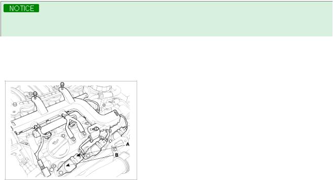
3.Remove the ignition coil connectors(A) and ignition coils(B).
4.Remove the spark plugs.
Using a 16mm plug wrench, remove the 6 spark plugs.
5.Check cylinder compression pressure.
(1)Insert a compression gauge into the spark plug hole.
(2)Fully open the throttle.
(3) After 7 times of cranking the engine, measure the compression pressure.
Always use a fully charged battery to obtain engine speed of 250 rpm or more.
Repeat steps 1) through 3) for each cylinder.
This measurement must be done in as short a time as possible.
Compression pressure :
1,225kPa (12.5kgf/cm!, 177psi) - 200 ~ 250rpm Minimum pressure :
1,078kPa (11.0kgf/cm!, 156psi)
(4)If the cylinder compression in 1 or more cylinders is low, pour a small amount of engine oil into the cylinder through the spark plug hole and repeat steps (a) through (c) for cylinders with low compression.
A.If adding oil helps the compression, it is likely that the piston rings and/or cylinder bore are worn or damaged.
B.If pressure stays low, a valve may be sticking or seating is improper, or there may be leakage past the gasket.
6.Reinstall the spark plugs.
7.Install the ignition coil and ignition coil connectors.
8.Install the surge tank.
VALVE CLEARANCE INSPECTION AND ADJUSTMENT
Inspect and adjust the valve clearance when the engine is cold (Engine coolant temperature : 20°C) and cylinder head is installed on the cylinder block.
1.Remove the engine cover.
2.Remove air cleaner assembly.
3.Remove the surge tank.
4.Remove the cylinder head cover.
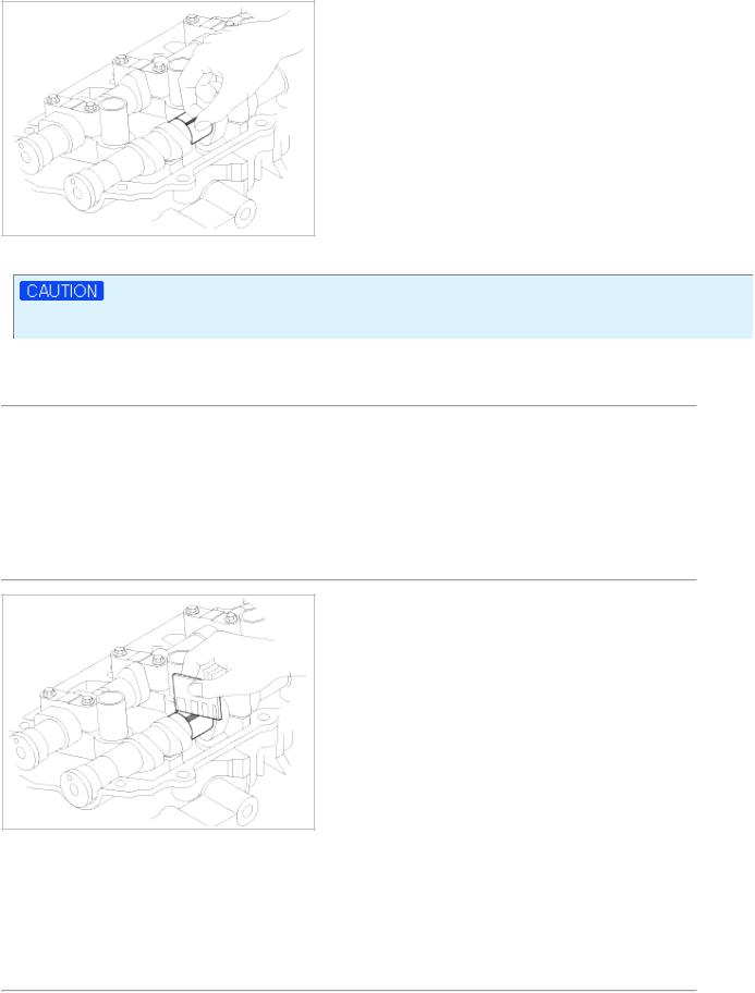
(1)Disconnect the ignition coil connector and remove the ignition coil.
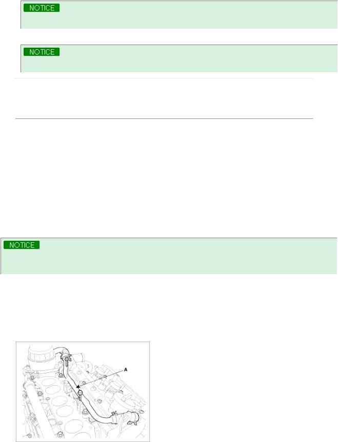
(2)Disconnect the breather pipe assembly(A) from the cylinder head cover.
(3) Loosen the cylinder head cover bolts and then remove the cover(A) and gasket.
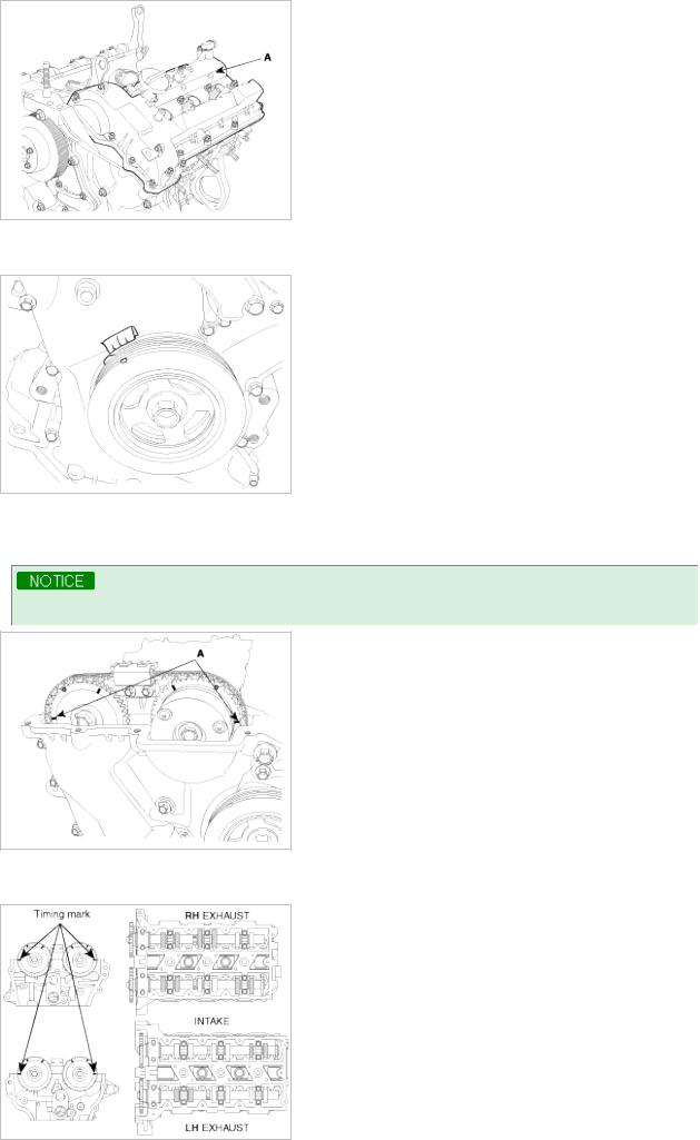
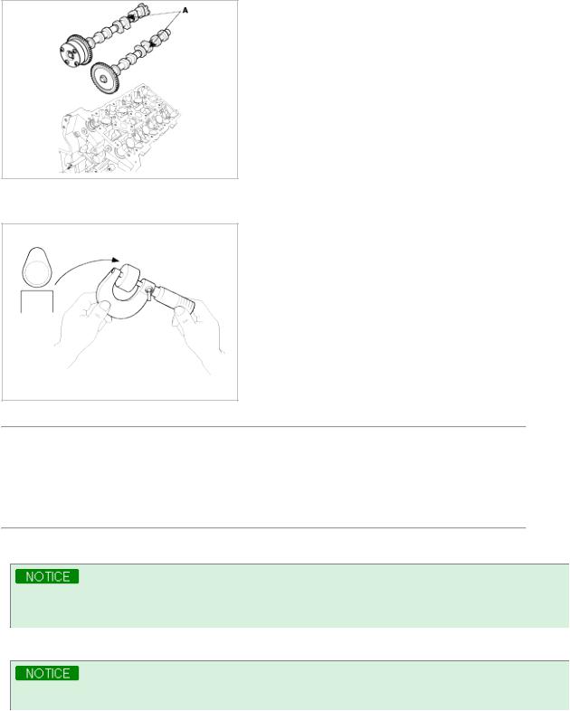
5.Set No.1 cylinder to TDC/compression.
(1)Turn the crankshaft pulley and align its groove with the timing mark "T" of the lower timing chain cover.
(2)Check that the mark(A) of the camshaft timing sprockets are in straight line on the cylinder head surface as shown in the illustration.
If not, turn the crankshaft one revolution (360°)
Do not rotate engine counterclockwise
6.Inspect the valve clearance.
(1)Check only the valve indicated as shown. [No. 1 cylinder : TDC/Compression] measure the valve clearance.
Measurement method.
A.$ Using a thickness gauge, measure the clearance between the tappet and the base circle of camshaft. $ Record the out-of-specification valve clearance measurements. They will be used later to determine the required replacement adjusting tappet.
Valve clearance Specification
Engine coolant temperature : 20°C [68°F] Limit
Intake : 0.10 ~ 0.30mm (0.0039 ~ 0.0118in.) Exhaust : 0.20 ~ 0.40mm (0.0079 ~ 0.0157in.)
(2)Turn the crankshaft pulley one revolution (360°) and align the groove with timing mark "T" of the lower timing chain cover.
Do not rotate engine counterclockwise
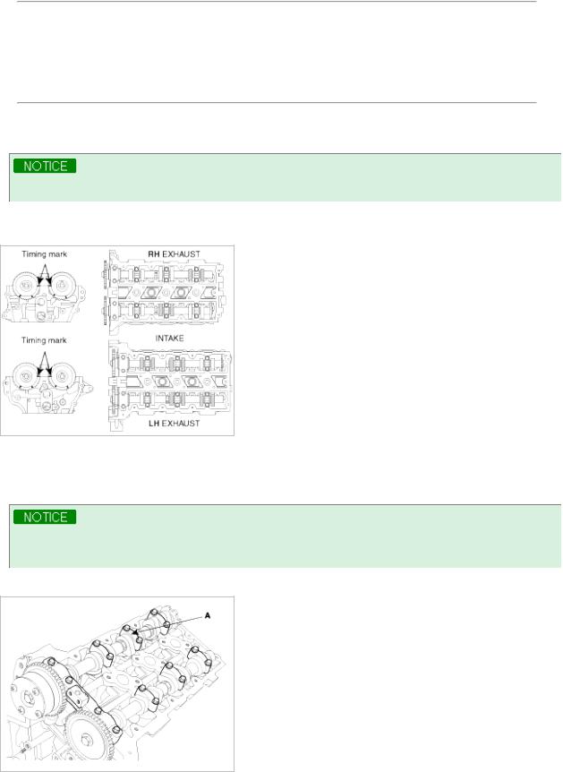
(3)Check only valves indicated as shown. [NO. 4 cylinder : TDC/compression]. Measure the valve clearance. (Refer to procedure step1))
7.Adjust the intake and exhaust valve clearance.
(1)Set the No.1 cylinder to the TDC/compression.
(2)Remove the timing chain.
Before removing the timing chain, mark the RH/LH timing chain with an identification based on the location of the sproket because the identification mark on the chain for TDC(Top Dead Center) can be erased.
(3) Remove the camshaft bearing caps(A).
(4) Remove the camshaft assembly(A).
(5)Remove MLAs.
(6)Measure the thickness of the removed tappet using a micrometer.
(7)Calculate the thickness of a new tappet so that the valve clearance comes within the specified value.
Valve clearance(Engine coolant temperature: 20°C[68°F]) T : Thickness of removed tappet
A : Measured valve clearance N : Thickness of new tappet
Intake : N = T + [A - 0.20mm(0.0079in.)] Exhaust : N = T + [A - 0.30mm (0.0118in.)]
(8)Select a new tappet with a thickness as close as possible to the calculated value.
Shims are available in 41size increments of 0.015mm (0.0006in.) from 3.00mm (0.118in.) to 3.600mm (0.1417in.)
(9) Place a new tappet on the cylinder head.
Appling engine oil at the selected tappet on the periphery and top surface.
(10)Install the intake and exhaust camshaft.
(11)Install the bearing caps
(12)Install the timing chain.
(13)Turn the crankshaft two turns in the operating direction(clockwise) and realign crankshaft sprocket and camshaft sprocket timing marks(A).
(14)Recheck the valve clearance.
Valve clearance (Engine coolant temperature: 20°C[68°F]) [Specification]
Intake : 0.17 ~ 0.23mm (0.0067 ~ 0.0090in.) Exhaust : 0.27 ~ 0.33mm (0.0106 ~ 0.0129in.)
2009 > G 3.8 DOHC >
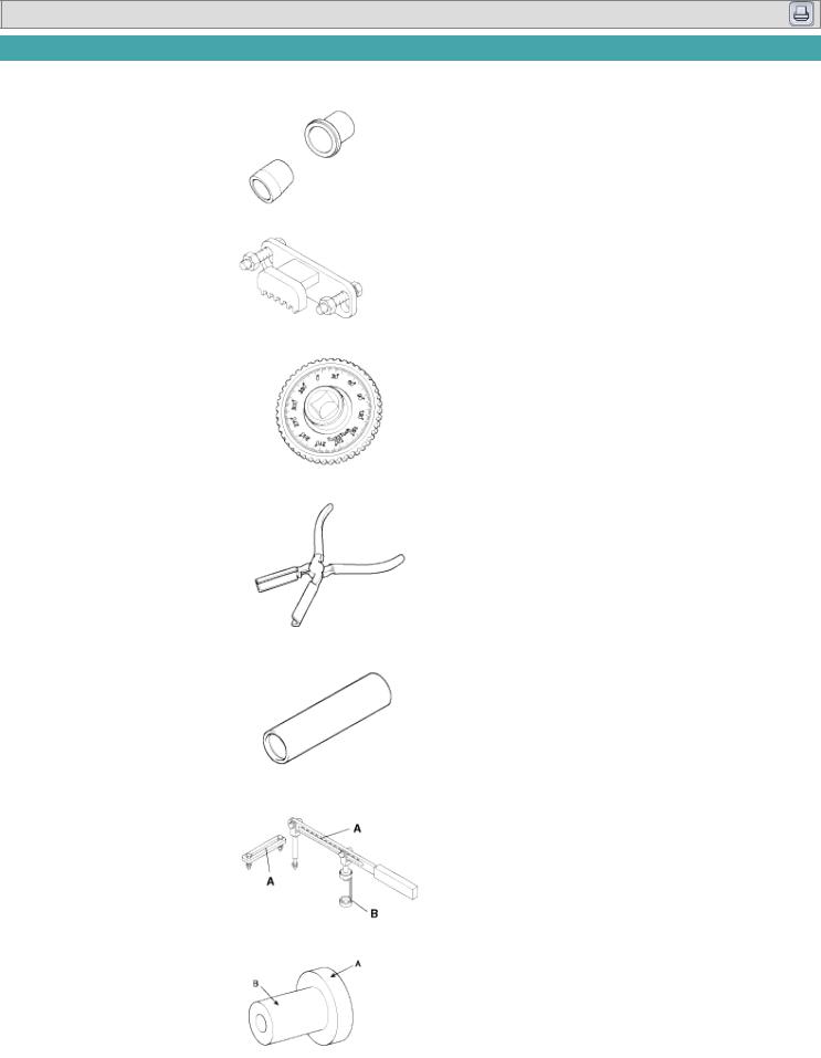
SPECIAL SERVICE TOOLS
Tool (Number and name) |
|
Illustration |
Use |
||
Crankshaft front oil seal |
|
|
|
|
Installation of the front oil seal |
|
|
|
|
||
installer |
|
|
|
|
|
(09231-3C100) |
|
|
|
|
|
|
|
|
|
|
|
|
|
|
|
|
|
Flywheel stopper |
|
|
|
|
Removal and installation of the flywheel and |
|
|
|
|
||
(09231-3C300) |
|
|
|
|
crankshaft pulley. |
|
|
|
|
|
|
|
|
|
|
|
|
Torque angle adapter |
|
|
|
|
Installation of bolts & nuts needing an angular |
|
|
|
|
||
(09221-4A000) |
|
|
|
|
method |
|
|
|
|
|
|
|
|
|
|
|
|
Valve stem seal remover |
|
|
|
|
Remover of the valve stem seal |
|
|
|
|
||
(09222-29000) |
|
|
|
|
|
|
|
|
|
|
|
|
|
|
|
|
|
Valve stem seal remover |
|
|
|
|
Installation of the valve stem seal |
|
|
|
|
||
(09222-3C100) |
|
|
|
|
|
|
|
|
|
|
|
|
|
|
|
|
|
Valve spring compressor & |
|
|
|
|
Removal and installation of the intake or |
|
|
|
|
||
holder |
|
|
|
|
exhaust valve |
(09222-3K000) |
|
|
|
|
A : 09222-3K000 |
(09222-3C300) |
|
|
|
|
B : 09222-3C300 (holder) |
|
|
|
|
|
|
|
|
|
|
|
|
Crankshaft rear oil seal |
|
|
|
|
Installation of the crankshaft rear oil seal |
|
|
|
|
||
installer |
|
|
|
|
A : 09231-3C200 |
(09231-3C200) |
|
|
|
|
B : 09231-H1100 |
(09231-H1100) |
|
|
|
|
|
|
|
|
|
|
|
|
|
|
|
|
|
|
|
|
|
|
|

Oil pan remover |
|
Removal of oil pan |
(09215-3C000) |
|
|
|
|
|
Oil filter wrench |
|
Removal and installation of the oil filter |
|
||
(09263-3C100) |
|
housing cover |
|
|
|

2009 > G 3.8 DOHC >
TROUBLESHOOTING
Symptom |
Suspect area |
Remedy |
|
Engine misfire with |
Worn crankshaft bearings. |
Replace the crankshaft and bearings as |
|
abnormal internal |
Loose or improperly installed engine drive |
required. |
|
lower engine noises. |
plate. |
Repair or replace the drive plate as required. |
|
|
|
|
|
|
Worn piston rings. |
Inspect the cylinder for a loss of compression. |
|
|
(Oil consumption may or may not cause the |
Repair or replace as required. |
|
|
engine to misfire.) |
|
|
|
|
|
|
|
Worn crankshaft thrust bearings |
Replace the crankshaft and bearings as |
|
|
required. |
||
|
|
||
|
|
|
|
Engine misfire with |
Stuck valves. |
Repair or replace as required. |
|
abnormal valve train |
(Carbon buildup on the valve stem) |
|
|
noise. |
|
|
|
Excessive worn or mis-aligned timing chain. |
Replace the timing chain and sprocket as |
||
|
|||
|
|
required. |
|
|
|
|
|
|
Worn camshaft lobes. |
Replace the camshaft and valve lifters. |
|
|
|
|
|
Engine misfire with |
• Malfunctioning cylinder head gasket and/or |
• Inspect the cylinder head and engine |
|
coolant consumption. |
cranking or other damage to the cylinder |
block for damage to the coolant passages |
|
|
head and engine block cooling system. |
and/or a malfunctioning head gasket. |
|
|
• Coolant consumption may or may not |
• Repair or replace as required. |
|
|
cause the engine to overheat. |
|
|
|
|
|
|
Engine misfire with |
Worn valves, guides and/or valve stem oil |
Repair or replace as required. |
|
excessive oil |
seals. |
|
|
consumption. |
|
|
|
Worn piston rings. |
• Inspect the cylinder for a loss of |
||
|
|||
|
(Oil consumption may or may not cause the |
compression. |
|
|
engine to misfire) |
• Repair or replace as required. |
|
|
|
|
|
Engine noise on start- |
Incorrect oil viscosity. |
• Drain the oil. |
|
up, but only lasting a |
|
• Install the correct viscosity oil. |
|
few seconds. |
|
|
|
Worn crankshaft thrust bearing. |
• Inspect the thrust bearing and crankshaft. |
||
|
|||
|
|
• Repair or replace as required. |
|
|
|
|
|
Upper engine |
Low oil pressure. |
Repair or replace as required. |
|
noise,regardless of |
|
|
|
Broken valve spring. |
Replace the valve spring. |
||
engine speed. |
|||
|
|
||
Worn or dirty valve lifters. |
Replace the valve lifters. |
||
|
|||
|
|
|
|
|
Stretched or broken timing chain and/or |
Replace the timing chain and sprockets. |
|
|
damaged sprocket teeth. |
|
|
|
|
|
|
|
Worn timing chain tensioner, if applicable. |
Replace the timing chain tensioner as |
|
|
|
required. |
|
|
|
|
|
|
Worn camshaft lobes. |
• Inspect the camshaft lobes. |
|
|
|
• Replace the timing camshaft and valve |
|
|
|
lifters as required. |
|
|
|
|
|
|
Worn valve guides or valve stems. |
Inspect the valves and valve guides,then |
|
|
|
repair as required. |
|
|
|
|
|
|
Stuck valves. (Carbon on the valve stem or |
Inspect the valves and valve guides, then |
|
|
valve seat may cause the valve to stay open. |
repair as required. |
|
|
|
|
|
|
Worn drive belt, idler, tensioner and bearing. |
Replace as required. |
|
|
|
|
|
Lower engine |
Low oil pressure. |
Repair or required. |
noise,regardless of |
|
|
|
Loose or damaged drive plate. |
Repair or replace the drive plate. |
||
engine speed. |
|||
|
|
||
Damaged oil pan, contacting the oil pump |
• Inspect the oil pan. |
||
|
|||
|
screen. |
• Inspect the oil pump screen. |
|
|
|
• Repair or replace as required. |
|
|
|
|
|
|
Oil pump screen loose, damaged or |
• Inspect the oil pump screen. |
|
|
restricted. |
• Repair or replace as required. |
|
|
|
|
|
|
Excessive piston-to-cylinder bore clearance. |
• Inspect the piston, piston pin and cylinder |
|
|
|
bore. |
|
|
|
• Repair as required. |
|
|
|
|
|
|
Excessive piston pin-to-piston clearance. |
• Inspect the piston, piston pin and the |
|
|
|
connecting rod. |
|
|
|
• Repair or replace as required. |
|
|
|
|
|
|
Excessive connecting rod bearing clearance |
Inspect the following components and repair |
|
|
|
as required. |
|
|
|
• The connecting rod bearings. |
|
|
|
• The connecting rods. |
|
|
|
• The crankshaft pin journals. |
|
|
|
|
|
|
Excessive crankshaft bearing clearance. |
Inspect the following components, and repair |
|
|
|
as required. |
|
|
|
• The crankshaft bearings. |
|
|
|
• The crankshaft main journals. |
|
|
|
• The cylinder block. |
|
|
|
|
|
|
Incorrect piston, piston pin and connecting rod |
• Verify the piston pins and connecting rods |
|
|
installation |
are installed correctly. |
|
|
|
• Repair as required. |
|
|
|
|
|
Engine noise under |
Low oil pressure |
Repair or replace as required. |
|
load. |
|
|
|
Excessive connecting rod bearing clearance . |
Inspect the following components andrepair |
||
|
|||
|
|
as required : |
|
|
|
• The connecting rod bearings. |
|
|
|
• The connecting rods. |
|
|
|
• The crankshaft. |
|
|
|
|
|
|
Excessive crankshaft bearing clearance. |
Inspect the following components, andrepair |
|
|
|
as required. |
|
|
|
• The crankshaft bearings. |
|
|
|
• The crankshaft main journals. |
|
|
|
• The cylinder block. |
|
|
|
|
|
Engine will not crank- |
Hydraulically locked cylinder. |
1. Remove spark plugs and check for fluid. |
|
crankshaft will not |
• Coolant/antifreeze in cylinder. |
2. Inspect for broken head gasket. |
|
rotate. |
• Oil in cylinder. |
3. Inspect for cracked engine block or |
|
|
• Fuel in cylinder. |
cylinder head. |
|
|
|
4. Inspect for a sticking fuel injector and/or |
|
|
|
leaking fuel regulator. |
|
|
|
|
|
|
Broken timing chain and/or timing chain |
1. Inspect timing chain and gears. |
|
|
and/or timing chain gears. |
2. Repair as required. |
|
|
|
|
|
|
Material in cylinder. |
1. Inspect cylinder for damaged components |
|
|
• Broken valve |
and/or foreign materials. |
|
|
• Piston material |
2. Repair or replace as required. |
|
|
• Foreign material |
|
|
|
|
|

|
Seized crankshaft or connecting rod bearings. |
1. Inspect crankshaft and connecting rod |
|
|
|
|
bearing. |
|
|
2. |
Repair as required. |
|
|
|
|
|
Bent or broken connecting rod. |
1. Inspect connecting rods. |
|
|
|
2. |
Repair as required. |
|
|
|
|
|
Broken crankshaft. |
1. |
Inspect crankshaft. |
|
|
2. |
Repair as required. |
|
|
|
|

Engine Mechanical System
Timing System
Engine Mechanical System
2009 > G 3.8 DOHC >
COMPONENT


Engine Mechanical System
Cylinder Head Assembly
Engine Mechanical System
2009 > G 3.8 DOHC >
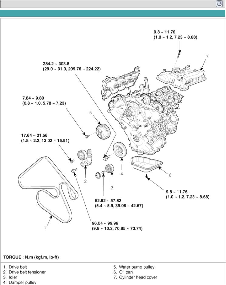
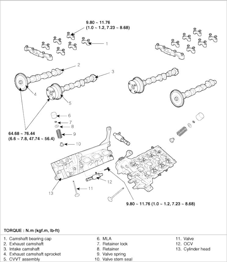
COMPONENTS
2009 > G 3.8 DOHC >
REMOVAL
•Use fender covers to avoid damaging painted surfaces.
•To avoid damaging the cylinder head, wait until the engine coolant temperature drops below normal operating temperature before removing it.
•When handling a metal gasket, take care not to fold the gasket or damage the contact surface of the gasket.
•To avoid damage, unplug the wiring connectors carefully while holding the connector portion.
•Mark all wiring and hoses to avoid misconnection.
•Turn the crankshaft pulley so that the No. 1 piston is at top dead center.
Engine removal is required for this procedure.
1.Remove exhaust manifold.
2.Remove intake manifold.
3.Remove timing chain.
4.Remove water temperature control assembly.
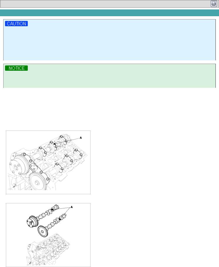
5.Remove camshaft bearing cap(A).
6. Remove camshaft assembly(A).
7.Remove cylinder head bolts, then remove cylinder head.
(1)Uniformly loosen and remove the 16 cylinder head bolts, in several passes, in the sequence shown. Remove the 16 cylinder head bolts and plate washers.
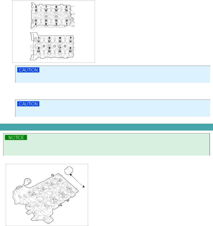
Head warpage or cracking could result from removing bolts in an incorrect order.
(2)Lift the cylinder head from the dowels on the cylinder block and place the cylinder head on wooden blocks on a bench.
Be careful not to damage the contact surfaces of the cylinder head and cylinder block.
DISASSEMBLY
Identify MLA, valves and valve springs as they are removed so that each item can be reinstalled in its original position.
1. Remove MLAs(A).
2.Remove valves.
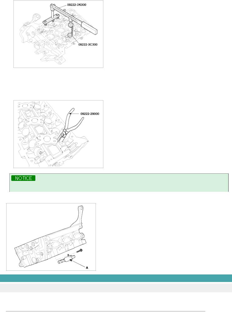
(1)Using SST(09222-3K000, 09222-3C300), compress the valve spring and remove retainer lock.
(2)Remove the spring retainer.
(3)Remove the valve spring.
(4)Remove the valve.
(5)Using SST(09222-29000), remove the valve stem seal.
Do not reuse old valve stem seals.
3. Remove OCV(A).
INSPECTION
CYLINDER HEAD
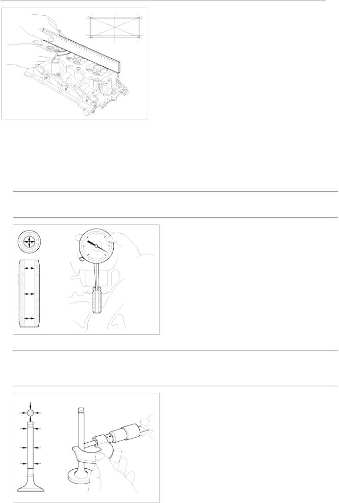
1.Inspect for flatness.
Using a precision straight edge and feeler gauge, measure the surface the contacting the cylinder block and the manifolds for warpage.
Flatness of cylinder head gasket surface
Standard : Less than 0.05mm(0.002in.)[Less than 0.02mm(0.0008in.)/150x150]
Flatness of manifold gasket surface
Standard : Less than 0.03mm(0.001in)/110x110
2.Inspect for cracks.
Check the combustion chamber, intake ports, exhaust ports and cylinder block surface for cracks. If cracked, replace the cylinder head.
VALVE AND VALVE SPRING
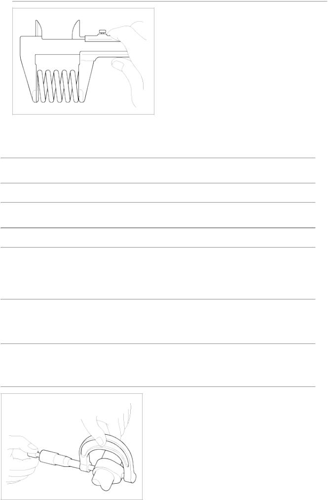
1.Inspect valve stems and valve guides.
(1)Using a caliper gauge, measure the inside diameter of the valve guide.
Valve guide I.D.
Intake / Exhaust : 5.500 ~ 5.512mm (0.216 ~ 0.217in.)
(2)Using a micrometer, measure the diameter of the valve stem.
Valve stem O.D.
Intake : 5.465 ~ 5.480mm (0.2151 ~ 0.2157in.) Exhaust : 5.458 ~ 5.470mm (0.2149 ~ 0.2153in.)
(3)Subtract the valve stem diameter measurement from the valve guide inside diameter measurement.
Valve stem-to-guide clearance
[Standard]
Intake : 0.020 ~ 0.047mm (0.0008 ~ 0.0018in.) Exhaust : 0.030 ~ 0.054mm (0.0012 ~ 0.0021in.) [Limit]
Intake : 0.07mm (0.0027in.) Exhaust : 0.09mm (0.0035in.)
2.Inspect valves.
(1)Check the valve is ground to the correct valve face angle.
(2)Check that the surface of the valve for wear. If the valve face is worn, replace the valve.
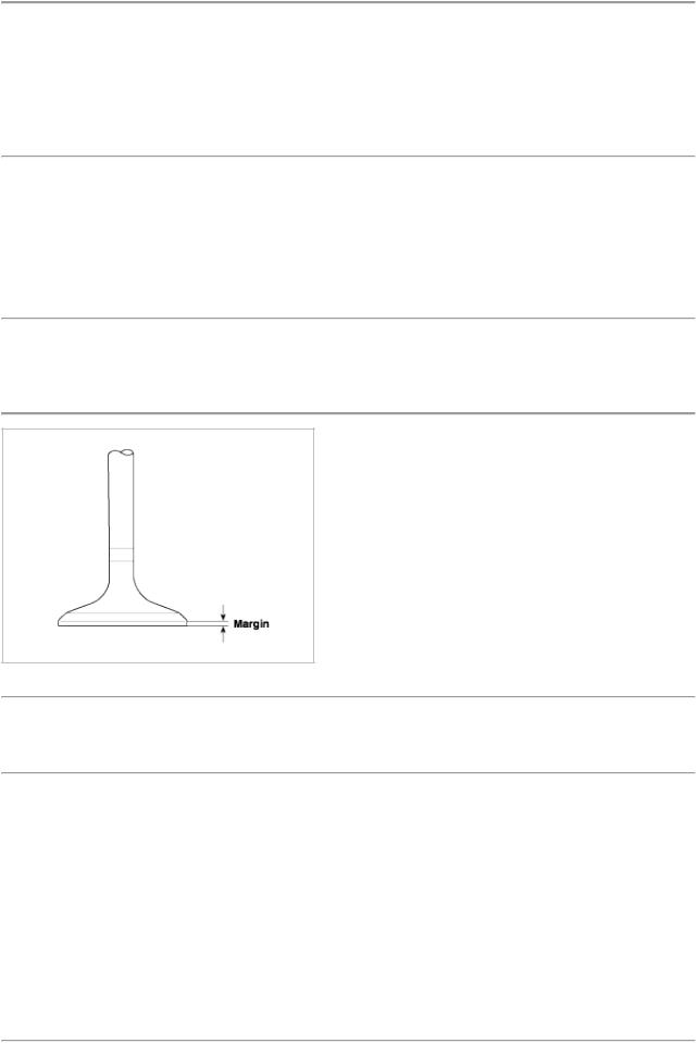
(3)Check the valve head margin thickness.
If the margin thickness is less than minimum, replace the valve.
Margin
[Standard]
Intake : 1.56 ~ 1.86mm(0.06142 ~ 0.07323in.) Exhaust : 1.73 ~ 2.03mm(0.06811 ~ 0.07992in.)
(4)Check the valve length.
Length
Intake : 105.27mm (4.1445in) Exhaust : 105.50mm (4.1535in)
(5)Check the surface of the valve stem tip for wear. If the valve stem tip is worn, replace the valve.
3.Inspect valve seats
Check the valve seat for evidence of overheating and improper contact with the valve face. If the valve seat is worn, replace cylinder head.
Before reconditioning the seat, check the valve guide for wear. If the valve guide is worn, replace cylinder head. Recondition the valve seat with a valve seat grinder or cutter. The valve seat contact width should be within specifications and centered on the valve face.
4.Inspect valve springs.
(1)Using a steel square, measure the out-of-square of the valve spring.
(2)Using a vernier calipers, measure the free length of the valve spring.
Valve spring
[Standard]
Free height : 43.86mm (1.7267in.)
Out-of-square : 1.5°
MLA
1.Inspect MLA.
Using a micrometer, measure the MLA outside diameter.
MLA O.D.
Intake/Exhaust : 34.964 ~ 34.980mm(1.3765 ~ 1.3771in.)
2.Using a caliper gauge, measure MLA tappet bore inner diameter of cylinder head.
Tappet bore I.D.
Intake/Exhaust : 35.000 ~ 35.025mm(1.3779 ~ 1.3789in.)
3.Subtract MLA outside diameter measurement from tappet bore inside diameter measurement.
MLA to tappet bore clearance
[Standard]
Intake/Exhaust : 0.020 ~ 0.061mm(0.0008 ~ 0.0024in.) [Limit]
Intake/Exhaust : 0.07mm(0.0027in.)
CAMSHAFT
1.Inspect cam lobes.
Using a micrometer, measure the cam lobe height.
Cam height
[Standard value]
Intake : 46.8mm (1.8425in.) Exhaust : 45.8mm (1.8031in.)
If the cam lobe height is less than standard, replace the camshaft.
2.Inspect camshaft journal clearance.
(1)Clean the bearing caps and camshaft journals.
(2)Place the camshafts on the cylinder head.
(3)Lay a strip of plastigage across each of the camshaft journal.
(4) Install the bearing caps.
Do not turn the camshaft.
(5)Remove the bearing caps.
(6)Measure the plastigage at its widest point.
Bearing oil clearance
[Standard value] Intake
No.1 journal : 0.020 ~ 0.057mm (0.0008 ~ 0.0022in.) No.2,3,4 journal : 0.030 ~ 0.067mm (0.0012 ~ 0.0026in.) Exhaust
No.1 journal : 0.020 ~ 0.057mm (0.0008 ~ 0.0022in.) No.2,3,4 journal : 0.030 ~ 0.067mm (0.0012 ~ 0.0026in.)
If the oil clearance is greater than maximum, replace the camshaft. If necessary, replace cylinder head.
(7)Completely remove the plastigage.
(8)Remove the camshafts.
3.Inspect camshaft end play.
(1)Install the camshafts.
(2)Using a dial indicator, measure the end play while moving the camshaft back and forth.
Camshaft end play
[Standard value] : 0.02 ~ 0.18mm(0.0008 ~ 0.0071in.)
If the end play is greater than maximum, replace the camshaft. If necessary, replace cylinder head.
(3) Remove the camshafts.
CVVT ASSEMBLY
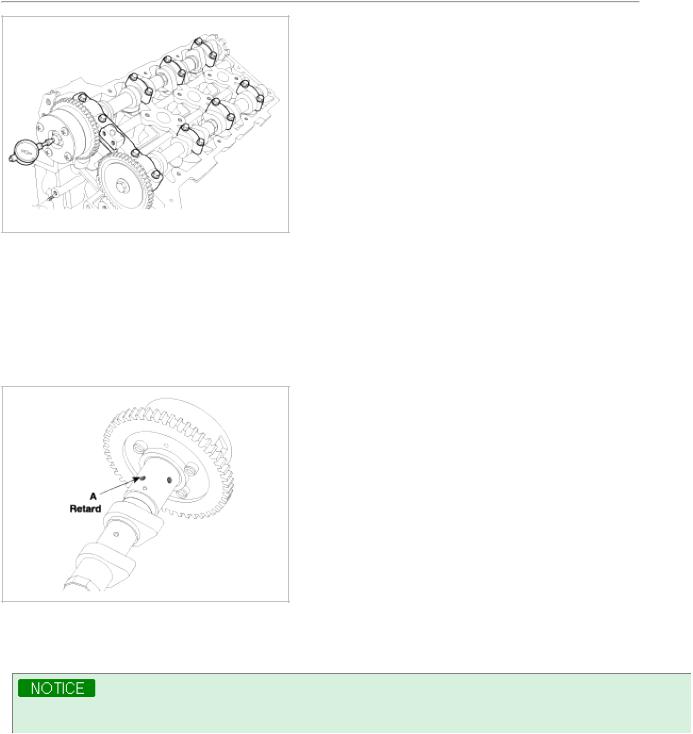
1.Inspect CVVT assembly.
(1)Check that the CVVT assembly will not turn.
(2)Apply vinyl tape to the retard hole except the one indicated by the arrow in the illustration.
(3)Wind tape around the tip of the air gun and apply air of approx. 150kpa(1.5kgf/cm!, 21psi) to the port of the camshaft.
(Perform this order to release the lock pin for the maximum delay angle locking.)
When the oil splashes, wipe it off with a shop rag.
(4)Under the condition of (3), turn the CVVT assembly to the advance angle side (the arrow marked direction in the illustration) with your hand.
Depending on the air pressure, the CVVT assembly will turn to the advance side without applying force by hand. Also, If excessive air leaks from the port, the lock pin may not be fully released.
 Loading...