


2008 Kia Sedona EX
2008 ACCESSORIES & BODY, CAB Body (Interior & Exterior) - General - Sedona
2008 ACCESSORIES & BODY, CAB
Body (Interior & Exterior) - General - Sedona
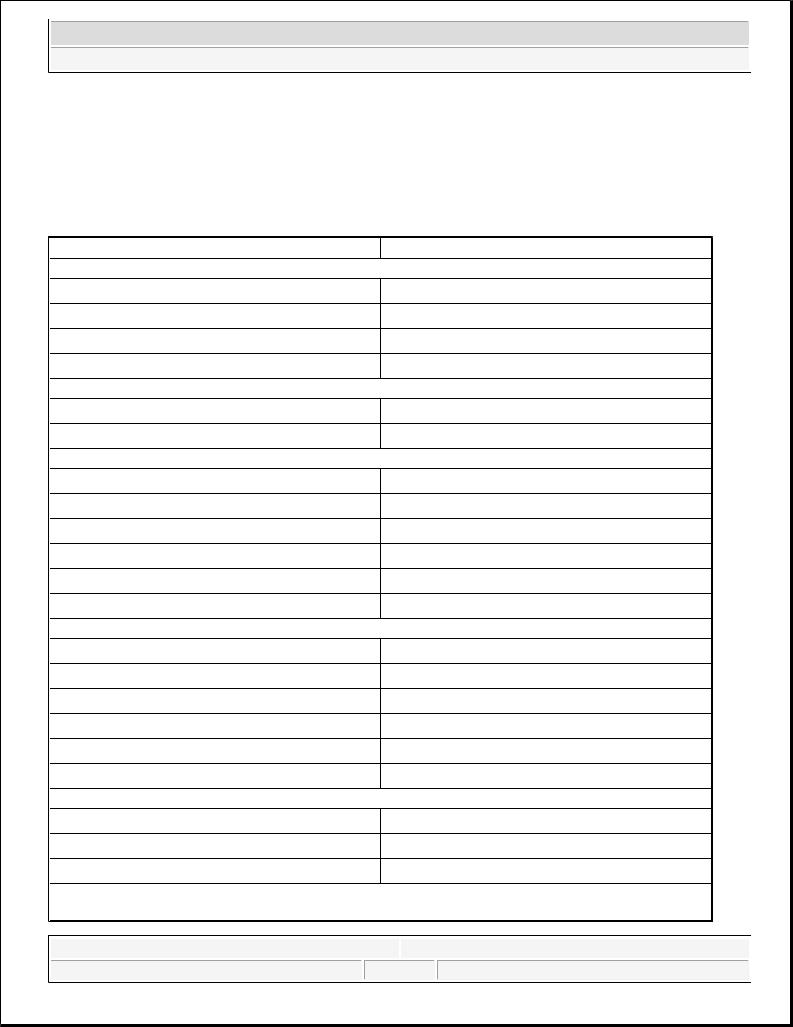
SPECIFICATIONS
GENERAL SPECIFICATIONS |
|
|
HOOD |
Type |
Rear hinged, gas lifter type |
FRONT DOOR |
Construction |
Front hinged, full door |
|
|
construction |
|
Regulator system |
X-ARM type |
|
Locking system |
Pin-fork system |
REAR DOOR |
Construction |
Sliding door construction |
|
Regulator system |
Wire drum type |
|
Locking system |
Pin-fork system |
TAILGATE |
Type |
Inner hinged, gas lifter type |
GLASS THICKNESS |
Windshield glass |
5 mm |
|
Front door glass |
4 mm |
|
Rear door glass |
4 mm |
|
Rear window glass |
3.5 mm |
SEAT BELTS |
Front |
3 point type with Emergency |
|
|
Locking Retractor (ELR) |
|
Rear |
3 point type with Emergency |
|
|
Locking Retractor (ELR) |
TIGHTENING TORQUE
TIGHTENING TORQUE SPECIFICATIONS |
|
|
|
||||||||
|
|
Items |
|
|
N.m |
Kgf. m |
Lbf. ft |
||||
Front and rear doors Door hinge to body |
33.3-41.2 |
3.4-4.2 |
24.6-30.4 |
|
|||||||
|
|
|
Door hinge to door |
21.6-26.5 |
2.2-2.7 |
15.9-19.5 |
|
||||
|
|
|
Striker |
6.9-10.8 |
0.7-1.1 |
5.1-8.0 |
|
||||
|
|
|
Glass mounting bolt |
7.8-11.8 |
0.8-1.2 |
5.8-8.7 |
|
||||
|
|
|
Outside handle |
6.9-10.8 |
0.7-1.1 |
5.1-8.0 |
|
||||
|
|
|
mounting bolt |
|
|
|
|
|
|
|
|
|
|
|
Rear channel |
7.8-11.8 |
0.8-1.2 |
5.8-8.7 |
|
||||
|
|
|
mounting nut |
|
|
|
|
|
|
|
|
Tailgate |
|
Tailgate hinge to |
6.9-8.8 |
0.7-0.9 |
5.1-6.5 |
|
|||||
|
|
|
body |
|
|
|
|
|
|
|
|
|
|
|
Tailgate hinge to |
6.9-8.8 |
0.7-0.9 |
5.1-6.5 |
|
||||
|
|
|
tailgate |
|
|
|
|
|
|
|
|
|
|
|
Tailgate lift |
6.9-8.8 |
0.7-0.9 |
5.1-6.5 |
|
||||
|
|
|
mounting bolt |
|
|
|
|
|
|
|
|
|
|
|
|
|
|
|
|
|
|
|
|
|
Microsoft |
|
|
|
|
|
|
|
|
|
|
|
|
|
|
|
© 2006 Mitchell Repair Information Company, LLC. |
||||||
|
Monday, May 24, 2010 4:05:1108 PM |
|
|
Page 1 |
|||||||
|
|
|
|
|
|
|
|
|
|
|
|
2008 Kia Sedona EX
2008 ACCESSORIES & BODY, CAB Body (Interior & Exterior) - General - Sedona
|
Key cylinder |
6.9-10.8 |
0.7-1.1 |
5.1-8.0 |
|
mounting nut |
|
|
|
Hood |
Hood hinge to body |
21.6-26.5 |
2.2-2.7 |
15.9-19.5 |
|
Hood hinge to hood |
21.6-26.5 |
2.2-2.7 |
15.9-19.5 |
|
Hood latch to body |
6.9-10.8 |
0.7-1.1 |
5.1-8.0 |
Seat |
Front seat mounting |
43.1-64.7 |
4.4-6.6 |
31.8-47.7 |
|
bolts |
|
|
|
|
Rear seat mounting |
43.1-64.7 |
4.4-6.6 |
31.8-47.7 |
|
bolts |
|
|
|
Seat belt |
Front seat belt |
39.2-53.9 |
4.0-5.5 |
28.9-39.8 |
|
height adjuster |
|
|
|
|
Front seat belt |
39.2-53.9 |
4.0-5.5 |
28.9-39.8 |
|
buckle mounting |
|
|
|
|
bolt |
|
|
|
|
Front seat belt |
39.2-53.9 |
4.0-5.5 |
28.9-39.8 |
|
anchor mounting |
|
|
|
|
bolt |
|
|
|
|
Front seat belt lower |
39.2-53.9 |
4.0-5.5 |
28.9-39.8 |
|
anchor |
|
|
|
|
Front seat belt upper |
39.2-53.9 |
4.0-5.5 |
28.9-39.8 |
|
anchor |
|
|
|
|
Rear seat belt |
39.2-53.9 |
4.0-5.5 |
28.9-39.8 |
|
anchor attaching |
|
|
|
|
bolt |
|
|
|
|
Rear seat belt |
39.2-53.9 |
4.0-5.5 |
28.9-39.8 |
|
retractor mounting |
|
|
|
|
bolt |
|
|
|
SPECIAL TOOLS
SPECIAL TOOLS REFERENCE CHART |
|
|
Tool (Number and name) |
Illustration |
Use |
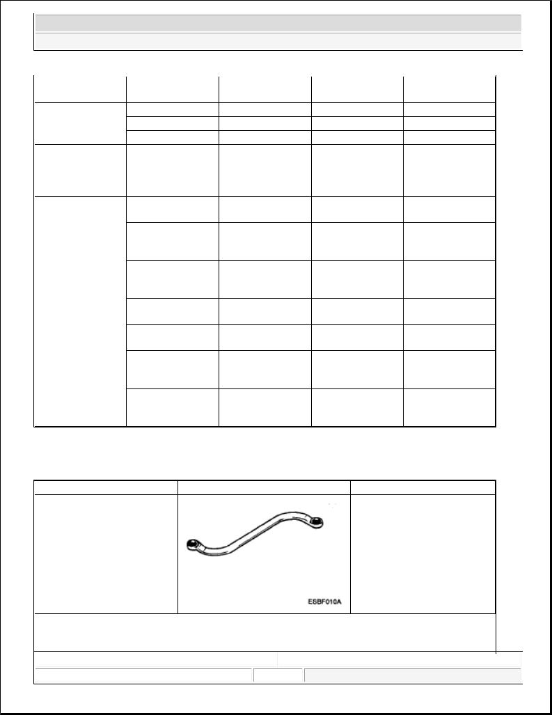
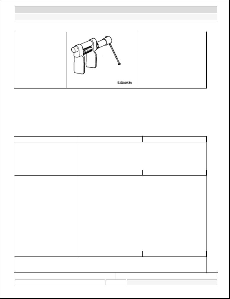
09793-2100 |
|
Adjustment, removal and |
Door hinge adjusting wrench |
|
installation |
|
|
Of the door hinge |
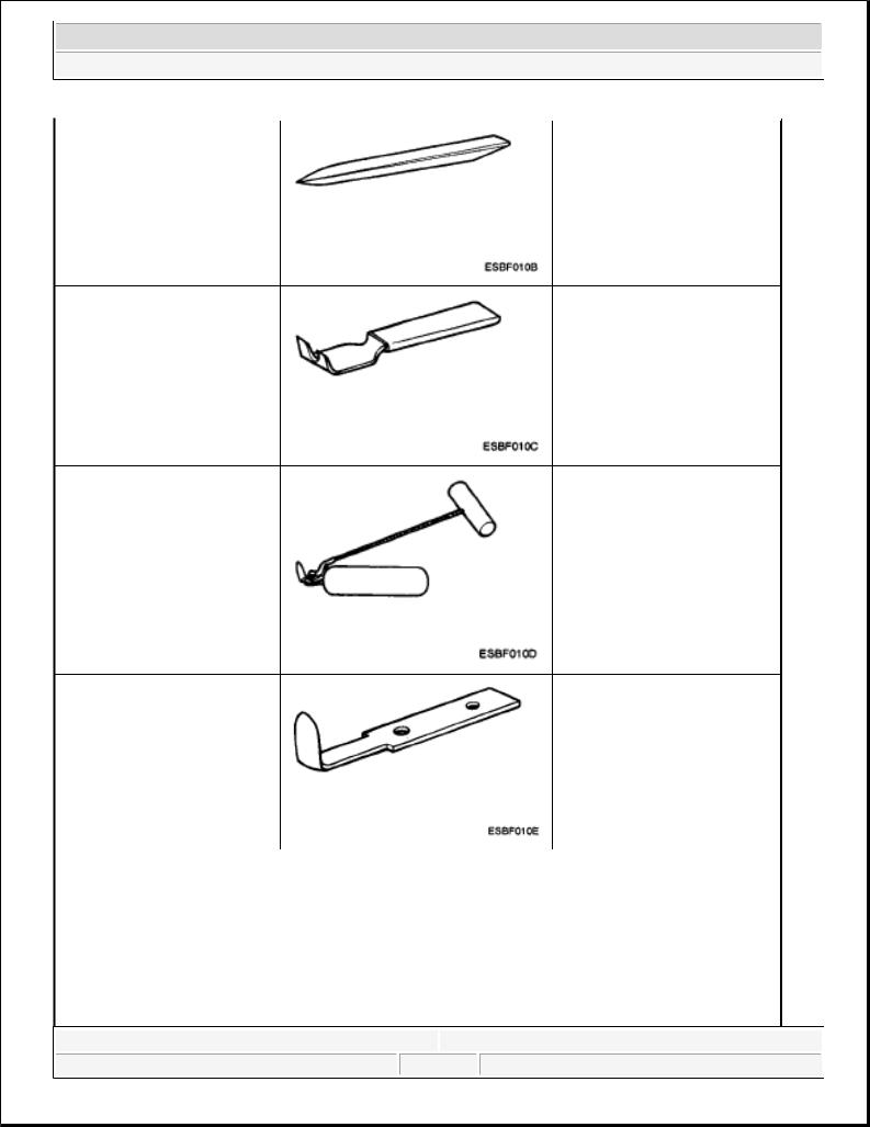
09800-21000 |
|
|
|
|
|
|
Trim removal |
|
|
|
Ornament remover |
|
|
|
|
|
|
|
|
|
|
|
|
|
|
|
|
|
|
|
|
|
|
|
|
|
|
|
|
|
|
|
|
|
Microsoft |
|
|
|
|
|
|
|
|
|
|
|
|
|
|
© 2006 Mitchell Repair Information Company, LLC. |
|||||
|
Monday, May 24, 2010 4:05:08 PM |
|
|
Page 2 |
||||||
|
|
|
|
|
|
|
|
|
|
|
2008 Kia Sedona EX
2008 ACCESSORIES & BODY, CAB Body (Interior & Exterior) - General - Sedona
09853-31000 |
Removal of the headliner clips |
Headliner clip remover |
|
09861-31100 |
Cutting the sealant of the |
Sealant cut-out tool |
windshield |
|
(Use with 09861-31200) |
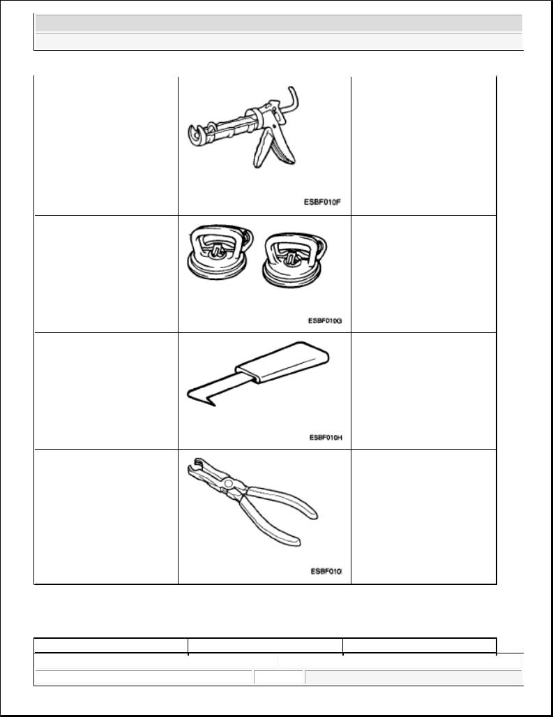
09861-31200 |
Cutting the sealant of the |
Sealant cutting blade |
windshield |
|
(Use with 09861-31100) |
09861-31300 |
|
Application of the sealant to the |
Sealant gun |
|
windshield |
|
|
|
Microsoft |
|
|
Monday, May 24, 2010 4:05:08 PM |
Page 3 |
© 2006 Mitchell Repair Information Company, LLC. |
2008 Kia Sedona EX
2008 ACCESSORIES & BODY, CAB Body (Interior & Exterior) - General - Sedona
09681-31400 |
Removal and installation of the |
Glass holder |
windshield |
09681-31000 |
Removal of the windshield |
Windshield molding remover |
molding |
09880-4F000 |
Installation of the hog ring clip |
Hog ring clip installer |
|
TROUBLESHOOTING
TROUBLESHOOTING CHART |
|
|
|
|
|
|
|
|
|
Symptom |
Suspect Area |
Remedy |
|||||
|
|
|
|
|
|
|
|
|
|
Microsoft |
|
|
|
|
|
|
|
|
|
|
|
|
© 2006 Mitchell Repair Information Company, LLC. |
|||
|
Monday, May 24, 2010 4:05:08 PM |
|
|
Page 4 |
||||
|
|
|
|
|
|
|
|
|
2008 Kia Sedona EX
2008 ACCESSORIES & BODY, CAB Body (Interior & Exterior) - General - Sedona
Water leaks from sunroof |
Dirt accumulated in drain tube |
Clear dirt inside of drain |
|
Clogged drain tube |
Blow air into drain to remove dirt |
|
Broken or dislocated drain tube, |
Check tube installation and Flange |
|
defective |
contact |
|
Or cracked clip |
|
|
Deteriorated roof lid weatherstrip |
Replace |
|
Excessive roof lid-to-body |
Adjust |
|
clearance and Improperly fitted |
|
|
weatherstrip |
|
Wind noise around sunroof |
Loose or deformed deflector, gaps |
Retighten adjust or replace |
|
In body work |
|
Sunroof lid makes a noise when |
Foreign particles lodged in guide |
Check drive cable and guide Rails |
moving |
rail |
for foreign particles |
|
Loose guide rails and lid |
Retighten |
Motor runs but sunroof does not |
Foreign particles lodged in guide |
Check drive cable and guide Rails |
move or moves only partially |
rail |
for foreign particles |
|
Incorrect engagement of motor |
Check for loose motor installation |
|
pinion With drive cable |
And damaged pinion |
Decrease in motor's clutch slipping Adjust force
Noise in motor (clutch slipping Noise from motor when sunroof Is fully opened or closed is not An unusual noise)
Increased sunroof sliding |
Adjust or replace |
resistance Or interference of |
|
sunroof with drive cables, |
|
weatherstrip, etc. due to |
|
maladjustment of sunroof |
|
Incorrect engagement of motor |
Check pinion installation and |
pinion With drive cable |
Retighten motor |
Worn out or damaged motor |
Replace motor assembly |
pinion bearing |
|
Worn out or deformed drive cable |
Replace |
Door glass fails to operate Up and |
Incorrect window glass installation Adjust position |
|||||||||
down |
Damaged or faulty regulator arm |
Correct or replace |
||||||||
|
|
or regulator |
|
|
|
|||||
Door does not open or close |
Incorrect door installation |
|
Adjust position |
|||||||
completely |
Defective door check assembly |
Correct or replace |
||||||||
|
|
Door hinge requires grease |
|
Apply grease |
||||||
Hood does not open or close |
Striker and latch not properly |
Adjust |
||||||||
completely |
aligned |
|
|
|
||||||
|
|
Incorrectly installed hood |
|
Adjust |
||||||
|
|
Incorrect hood bumper height |
Adjust |
|||||||
Water leak through windshield |
Defective seal |
|
Fill with sealant |
|||||||
end rear window |
Defective flange |
|
Correct |
|||||||
|
|
|
|
|
|
|
|
|
|
|
|
|
|
|
|
|
|
|
|
|
|
|
Microsoft |
|
|
|
|
|
|
|
|
|
|
|
|
|
|
|
© 2006 Mitchell Repair Information Company, LLC. |
||||
|
Monday, May 24, 2010 4:05:08 PM |
|
|
Page 5 |
|
|||||
|
|
|
|
|
|
|
|
|
|
|
2008 Kia Sedona
2008 BRAKES Brake System - General - Sedona
2008 BRAKES
Brake System - General - Sedona
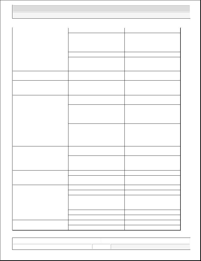
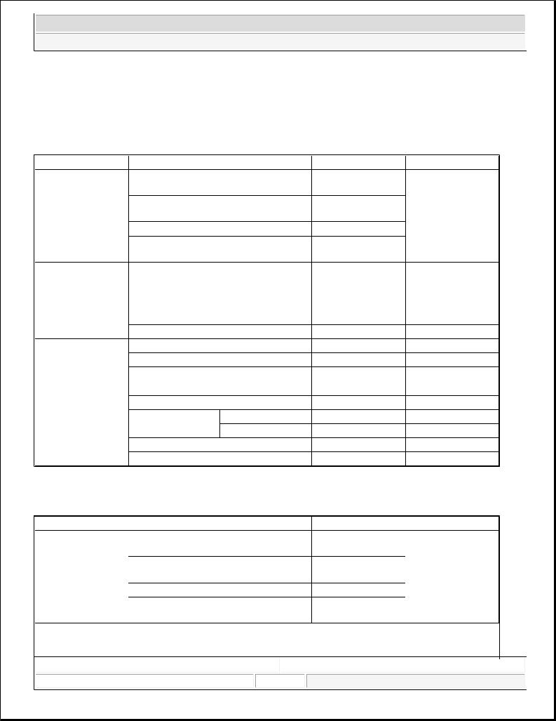
SPECIFICATIONS
BRAKE SYSTEM SPECIFICATIONS Item
Master cylinder
Type
I.D. mm (in)
Piston stroke mm (in)
Fluid level warning sensor Brake booster
Type
Boosting ratio
Front brake (Disc)
Type
Disc O.D.
Disc thickness
Pad thickness
Cylinder type
Cylinder I.D. Rear Brake (Disc)
Type
Disc O.D.
Disc thickness
Pad thickness
Cylinder type
Cylinder I.D Parking Brake
Type
Actuation
Drum
O.D=Outer Diameter
I.D=Inner Diameter
Specification
Tandem type 26.99/(1.063)
30 (1.18) Provided
8 + 9 in Tandem
9.0: 1
Floating type with ventilated disc 298 mm (11.73 in)
28 mm (1.10 in)
10.5 mm (0.41 in) Double piston Ø48 mm (Ø1.89 in)
Floating type with solid disc 302 mm (11.89 in)
12 mm (0.47 in)
10 mm (0.39 in) Single piston Ø42.9 mm (Ø1.69 in)
DIH (Drum in hat) Foot brake Ø190 mm (Ø7.48 in)
Microsoft |
|
|
Saturday, May 22, 2010 6:55:041 PM |
Page 1 |
© 2006 Mitchell Repair Information Company, LLC. |
2008 Kia Sedona
2008 BRAKES Brake System - General - Sedona
NOTE: |
ABS: Anti-Lock Brake System |
|
ESC: Electronic Stability Control |
Part |
Item |
|
System |
HECU (Hydraulic |
Type |
and Electronic |
|
Control Unit) |
Operating voltage |
|
Operating temperature |
|
Operating voltage |
Warning lamp |
|
|
Current consumption |
|
Supply voltage |
|
Operating temperature |
|
Output current low |
Active wheel speed |
Output current High |
Frequency range |
sensor |
|
|
SPECIFICATION (ABS) |
|
|
ANTI-LOCK BRAKE SYSTEM SPECIFICATIONS |
||
Air gap |
Front |
|
Rear |
||
Tone wheel |
||
|
||
Output duty |
|
|
SPECIFICATION (ESC) |
|
|
Standard value |
Remark |
|
4 channel 4 sensor |
|
|
(Solenoid) |
|
|
Motor, valve relay |
•ABS system: ABS |
|
integrated type |
||
& EBD control |
||
8 V-16 V (DC) |
||
|
||
-40 to 120°C (-40 to |
|
|
248°F) |
|
|
12 V |
•ABS W/LABS |
|
|
failure |
|
|
•Brake W/L: |
|
|
Parking, brake oil, |
|
80 mA |
EBD failure |
|
|
||
DC 4.5-2.0 V |
|
|
-40-150 °C |
|
|
5.9-8.4 mA |
Typ.7 mA |
|
11.8-16.8 mA |
Typ.14 mA |
|
1-2500 HZ |
|
|
0.15-1.5 mm |
Typ.0.7 mm |
|
0.2-1.2 mm |
Typ.0.7 mm |
|
48 teeth |
|
|
30-70 % |
|
ELECTRONIC STABILITY CONTROL SPECIFICATIONS |
|
|
|
||||||||
|
Part |
Item |
|
|
|
|
|
Standard Value |
Remark |
||
|
|
System |
|
|
|
|
|
4 channel 4 sensor |
|
|
|
|
|
|
|
|
|
|
|
(Solenoid) |
|
|
|
HECU (Hydraulic |
Type |
|
|
|
|
|
Motor, valve relay |
•Total control (ABS, |
|||
and Electronic |
|
|
|
|
|
|
integrated type |
||||
|
|
|
|
|
|
EBD, TCS, ESC) |
|||||
Control Unit) |
Operating voltage |
|
|
|
|
|
8 V-16 V (DC) |
||||
|
|
|
|
|
|
|
|
||||
|
|
Operating temperature |
|
|
|
|
|
-40 to120°C (-40 to |
|
|
|
|
|
|
|
|
|
|
|
248°F) |
|
|
|
Warning lamp |
Operating voltage |
|
|
|
|
|
12 V |
•ESC Operating |
|
|
|
|
|
|
|
|
|
|
Lamp |
|
|
||
|
|
|
|
|
|
|
|
|
|
|
|
|
|
|
|
|
|
|
|
|
|
|
|
|
Microsoft |
|
|
|
|
|
|
|
|
|
|
|
|
|
|
|
© 2006 Mitchell Repair Information Company, LLC. |
||||||
|
Saturday, May 22, 2010 6:55:01 PM |
|
Page 2 |
|
|||||||
|
|
|
|
|
|
|
|
|
|
|
|
2008 Kia Sedona
2008 BRAKES Brake System - General - Sedona
Active wheel speed sensor
Steering Wheel
Angle Sensor
Yaw-rate & Lateral G sensor
Current consumption Supply voltage Operating temperature Output current low Output current high Tone wheel Frequency range
Air gap |
Front |
|
Rear |
||
|
Operating Voltage Current Consumption Operating Angular velocity Operating Voltage Current Consumption Output Voltage high Output Voltage low
Yaw Sensor Operating Range G Sensor Operating Range Reference voltage output
80 mA |
ESC Warning Lamp |
|
|
DC 4.5-20 V |
|
-40-150 °C |
|
5.9-8.4 mA |
|
11.8-16.8 mA |
|
48 teeth |
|
1-2500 HZ |
|
0.15-1.5 mm |
Type. 0.7 mm |
0.2-1.2 mm |
Type. 0.7 mm |
8V-16 V |
|
Max 150 mA |
|
Max ± 780 °/sec |
|
8 V-16 V |
|
Max. 120 mA |
|
4.35 V-4.65 V |
Type. 4.5 V |
0.35-0.65 V |
Type. 0.5 V |
±100 ° /s |
|
±1.8 G |
|
2.464-2.536 V |
Type. 2.5 V |
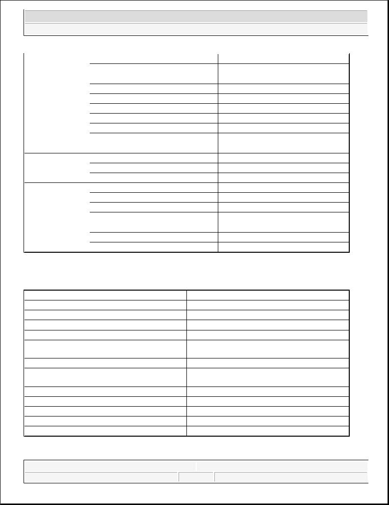
SERVICE STANDARD
SERVICE STANDARD SPECIFICATIONS |
|
Items |
Standard value |
Brake pedal height |
192.4 mm (7.57 in) |
Brake pedal full stroke |
122 mm (4.8 in) |
Adjust Brake pedal full stroke |
60 mm (2.36 in) |
Brake pedal free play |
3-8 mm (0.11-0.31 in) |
Stop lamp switch outer case to pedal stopper |
1.0-1.5 mm (0.04-0.06 in) |
clearance |
|
Booster push rod to master cylinder piston clearance |
0.6-1.7 mm (0.02-0.07 in) (at 500 mm.Hg) |
Parking brake pedal stroke when pedal assembly is |
145 mm (5.71 in) above |
depressed with 294N (30kgf, 661b force) |
|
Front disc brake pad thickness |
10.5 mm (0.41 in) |
Front disc thickness |
28 mm (1.10 in) |
Rear disc brake pad thickness |
10 mm (0.394 in) |
Rear disc brake disc thickness |
12 mm (0.47 in) |
Rear parking brake liner thickness |
4 mm (0.16 in) |
TIGHTENING TORQUE
Microsoft |
|
|
Saturday, May 22, 2010 6:55:01 PM |
Page 3 |
© 2006 Mitchell Repair Information Company, LLC. |
2008 Kia Sedona
2008 BRAKES Brake System - General - Sedona
TIGHTENING TORQUE SPECIFICATIONS |
|
|
|
Items |
N.m |
kgf.m |
lb-ft |
Master cylinder to booster mounting nut |
8-12 |
0.8-1.2 |
5.8-8.7 |
Brake booster mounting nut |
13-16 |
1.3-1.6 |
9.4-11.6 |
Bleeder screw |
7-13 |
0.7-1.3 |
5.06-9.4 |
Brake tube nut, brake hose |
13-17 1.3-1.7 |
9.4-12.3 |
|
Caliper guide rod bolt (Front) |
22-32 2.2-3.2 |
15.9-23.1 |
|
Caliper guide rod bolt (Rear) |
22-32 2.2-3.2 |
15.9-23.1 |
|
Caliper assembly to knuckle (Front) |
85-100 8.5-10 |
61.5-72.3 |
|
Caliper assembly to knuckle (Rear) |
50-60 5.0-6.0 |
36.2-43.4 |
|
Brake hose to front caliper |
25-30 2.5-3.0 |
18.1-21.7 |
|
Brake pedal assembly bracket mounting nut |
10-15 1.0-1.5 |
7.2-10.8 |
|
Brake pedal mounting nut |
13-16 |
1.3-1.6 |
9.4-11.6 |
Stop lamp switch mounting nut |
8-10 |
0.8-1.0 |
5.8-7.2 |
Active wheel speed sensor mounting bolt on the brake plate |
7-10 |
0.7-1.0 |
5.1-7.2 |
HECU mounting bracket bolt |
17-26 |
1.7-2.6 |
12.3-18.8 |
HECU mounting nut |
6-10 |
0.6-1.0 |
4.3-7.2 |
Yaw rate & lateral acceleration sensor bolt |
5-8 |
0.5-0.8 |
3.6-5.8 |
LUBRICANT |
|
|
LUBRICANT SPECIFICATIONS |
|
|
Item |
Recommended lubricant |
Quantity |
Brake fluid |
DOT 3 or DOT 4 |
As required |
Brake pedal bushing and brake pedal bolt |
Chassis grease |
As required |
Parking brake shoe and backing plate contact surfaces |
Bearing grease |
As required |
Caliper guide rod and boot |
RX - 2 grease |
0.8-1.3 g |
Rear caliper guide rod and boot |
Rubber grease |
0.8-1.3 g |
SPECIAL TOOL
SPECIAL TOOLS DESCRIPTION |
|
|
Tool (Number and Name) |
Illustration |
Use |
09581-11000 |
|
Spreading the front disc brake piston |
Piston expander |
|
|
|
|
|
|
|
|
Microsoft |
|
|
Saturday, May 22, 2010 6:55:01 PM |
Page 4 |
© 2006 Mitchell Repair Information Company, LLC. |
2008 Kia Sedona
2008 BRAKES Brake System - General - Sedona
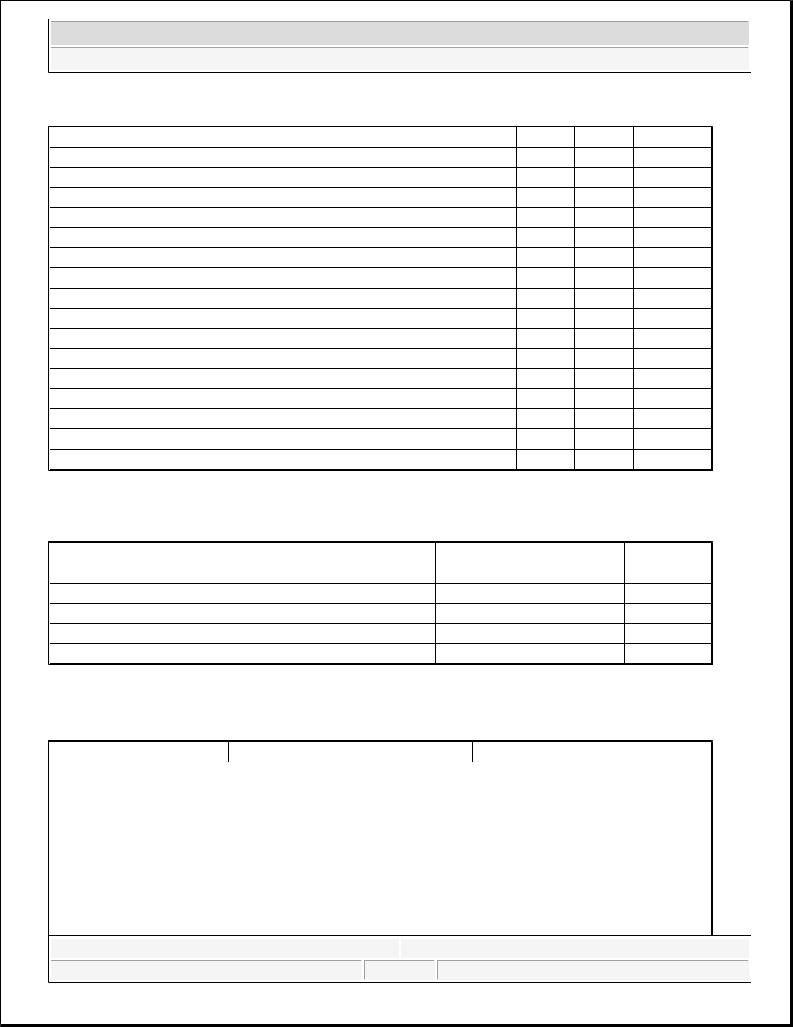
TROUBLESHOOTING
PROBLEM SYMPTOMS TABLE
Use the table below to help you find the cause of the problem. The numbers indicate the priority of the like cause of the problem. Check each part in order. If necessary, replace these parts
TROUBLESHOOTING CHART |
|
|
|
|
|
|
|
|
|
|
|
|
|
Symptom |
|
Suspect Area |
|
Reference |
|||||||
Lower pedal or spongy pedal |
1. Brake system (Fluid leaks) |
repair |
|
|
||||||||
|
|
2. |
Brake system (Air in) |
|
air-bleed |
|
|
|||||
|
|
3. |
Piston seals (Worn or damaged) |
replace |
|
|
||||||
|
|
4. |
Rear brake shoe clearance (Out |
adjust |
|
|
||||||
|
|
of adjustment) |
|
|
|
|
||||||
|
|
5. |
Master cylinder (Inoperative) |
replace |
|
|
||||||
Brake drag |
1. Brake pedal freeplay |
|
adjust |
|
|
|||||||
|
|
(Minimum) |
|
|
|
|
||||||
|
|
2. |
Parking brake lever travel (Out |
adjust |
|
|
||||||
|
|
of adjustment) |
|
|
|
|
||||||
|
|
3. |
Parking brake wire (Sticking) |
repair |
|
|
||||||
|
|
4. |
Rear brake shoe clearance (Out |
adjust |
|
|
||||||
|
|
of adjustment) |
|
|
|
|
||||||
|
|
5. |
Pad or lining (Cracked or |
|
replace |
|
|
|||||
|
|
distorted) |
|
|
|
|
||||||
|
|
6. |
Piston (Stuck) |
|
replace |
|
|
|||||
|
|
7. |
Piston (Frozen) |
|
replace |
|
|
|||||
|
|
8. |
Anchor or Return spring |
|
replace |
|
|
|||||
|
|
(Inoperative) |
|
|
|
|
||||||
|
|
9. |
Booster system (Vacuum leaks) |
repair |
|
|
||||||
|
|
10. Master cylinder (Inoperative) |
replace |
|
|
|||||||
Brake pull |
1. Piston (Sticking) |
|
replace |
|
|
|||||||
|
|
2. |
Pad or lining (Oily) |
|
replace |
|
|
|||||
|
|
|
|
|
|
|
|
|
|
|
|
|
|
|
|
|
|
|
|
|
|
|
|
|
|
|
Microsoft |
|
|
|
|
|
|
|
|
|
|
|
|
|
|
|
|
|
|
© 2006 Mitchell Repair Information Company, LLC. |
|||||
|
Saturday, May 22, 2010 6:55:01 PM |
|
|
|
Page 5 |
|
||||||
|
|
|
|
|
|
|
|
|
|
|
|
|
2008 Kia Sedona
2008 BRAKES Brake System - General - Sedona
Hard pedal but brake inefficient
Noise from brake
Brake fades
Brake vibration, pulsation
Brake Chatter
Microsoft
3. |
Piston (Frozen) |
replace |
4. |
Disc (Scored) |
replace |
5. |
Pad or lining (Cracked or |
replace |
distorted) |
|
|
1. |
Brake system (Fluid leaks) |
repair |
2. |
Brake system (Air in) |
air-bleed |
3. |
Pad or lining (Worn) |
replace |
4. |
Pad or lining (Cracked or |
replace |
distorted) |
|
|
5. |
Rear brake shoe clearance (Out |
adjust |
of adjustment) |
|
|
6. |
Pad or lining (Oily) |
adjust |
7. |
Pad or lining (Glazed) |
replace |
8. |
Disc (Scored) |
replace |
9. |
Booster system (Vacuum leaks) |
repair |
1. |
Pad or lining (Cracked or |
replace |
distorted) |
|
|
2. |
Installation bolt (Loosen) |
adjust |
3. |
Disc (Scored) |
replace |
4. |
Sliding pin (Worn) |
replace |
5. |
Pad or lining (Dirty) |
clean |
6. |
Pad or lining (Glazed) |
replace |
7. |
Anchor or Return spring |
replace |
(Inoperative) |
|
|
8. |
Brake pad shim (Damage) |
replace |
9. |
Shoe hold-down spring |
replace |
(Damage) |
|
|
1. master cylinder |
replace |
|
1. brake booster |
replace |
|
2. pedal free play |
adjust |
|
3. master cylinder |
replace |
|
4. caliper |
replace |
|
5. master cylinder cap seal |
replace |
|
6. damaged brake lines |
replace |
|
Brake chatter is usually caused by |
|
|
loose or worn components, or glazed or burnt linings. Rotors with hard spots can also contribute to brake chatter. Additional causes of chatter are out-of-tolerance rotors, brake lining not securely attached to the shoes, loose wheel bearings and contaminated brake lining.
Saturday, May 22, 2010 6:55:01 PM |
|
Page 6 |
© 2006 Mitchell Repair Information Company, LLC. |
2008 Kia Sedona
2008 ELECTRICAL Charging System - Sedona
2008 ELECTRICAL
Charging System - Sedona
DESCRIPTION
The charging system includes a battery, an generator with a built-in regulator, and the charging indicator light and wire.
The Generator has built-in diodes, each rectifying AC current to DC current.
Therefore, DC current appears at generator "B" terminal. In addition, the charging voltage of this generator is regulated by the battery voltage detection system.
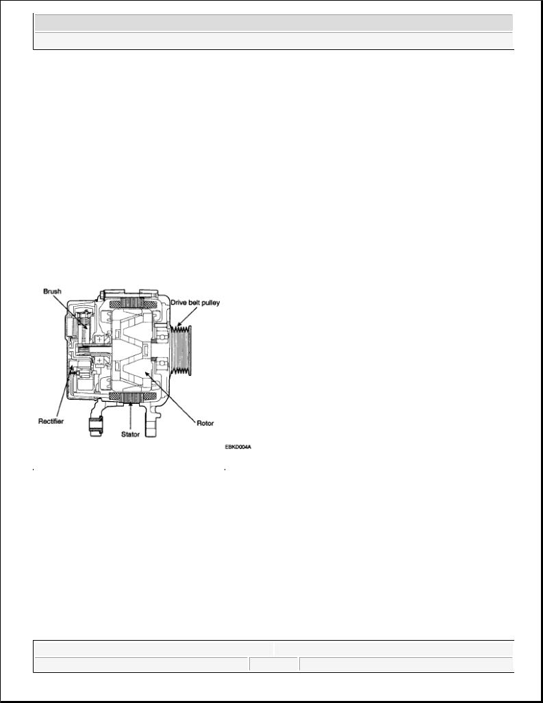
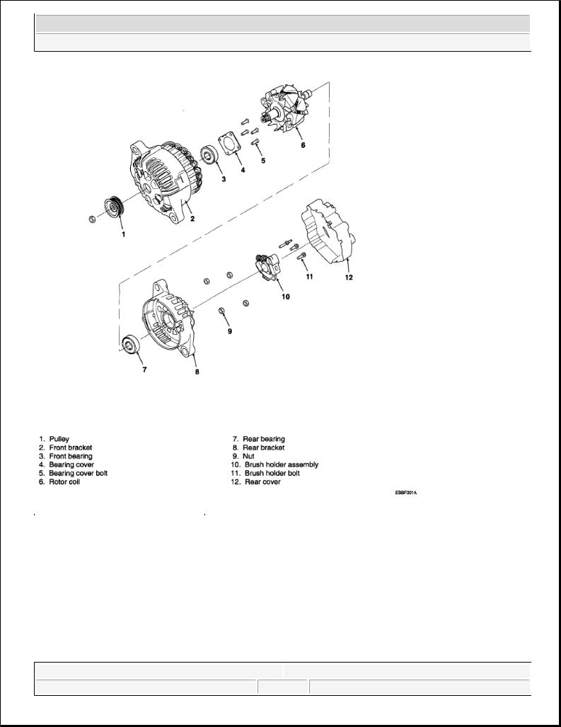
The main components of the generator are the rotor, stator, rectifier, capacitor brushes, bearings and V-ribbed belt pulley. The brush holder contains a built-in electronic voltage regulator.
Fig. 1: Identifying Generator Components
Courtesy of KIA MOTORS AMERICA, INC.
ON-VEHICLE INSPECTION
CAUTION: |
|
Check that the battery cables are connected to the correct terminals. |
|
|
Disconnect the battery cables when the battery is given a quick |
|
|
charge. |
|
|
Never disconnect the battery while the engine is running. |
CHECK BATTERY VOLTAGE
1. If 20 minutes have not passed since the engine was stopped, turn the ignition switch ON and turn on the
Microsoft |
|
|
Saturday, May 22, 2010 4:06:14 PM |
Page 1 |
© 2006 Mitchell Repair Information Company, LLC. |
2008 Kia Sedona
2008 ELECTRICAL Charging System - Sedona
electrical system (headlamp, blower motor, rear defogger etc.) for 60 seconds to remove the surface charge.
2.Turn the ignition switch OFF and turn off the electrical systems.
3.Measure the battery voltage between the negative (-) and positive (+) terminals of the battery. Standard voltage: 12.5-12.9V at 20°C (68°F)
If the voltage is less than specification, charge the battery.
CHECK THE BATTERY TERMINALS AND FUSES
1.Check that the battery terminals are not loose or corroded.
2.Check the fuses for continuity.
INSPECT DRIVE BELT
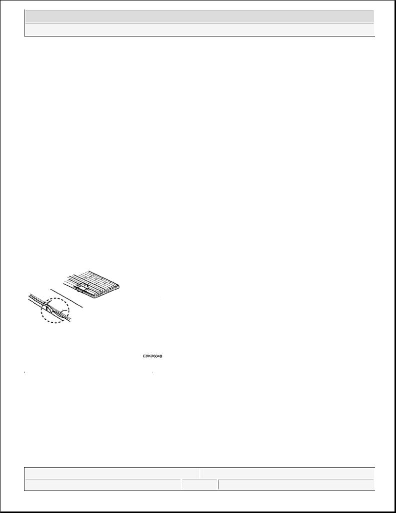
Visually check the belt for excessive wear, frayed cords etc.
If any defect has been found, replace the drive belt.
NOTE: |
Cracks on the rib side of a belt are considered acceptable. If the belt has |
|
chunks missing from the ribs, it should be replaced. |
Fig. 2: Identifying Defective Drive Belt
Courtesy of KIA MOTORS AMERICA, INC.
VISUALLY CHECK GENERATOR WIRING AND LISTEN FOR ABNORMAL NOISES
1.Check that the wiring is in good condition.
2.Check that there is no abnormal noise from the alternator while the engine is running.
CHECK BATTERY WARNING LIGHT CIRCUIT
1. Warm up the engine and then turn it off.
Microsoft |
|
|
Saturday, May 22, 2010 4:06:11 PM |
Page 2 |
© 2006 Mitchell Repair Information Company, LLC. |
2008 Kia Sedona
2008 ELECTRICAL Charging System - Sedona
2.Turn off all accessories.
3.Turn the ignition switch "ON". Check that the battery warning light is lit.
4.Start the engine. Check that the light is lit.
If the light does not go off as specified, troubleshoot the discharge light circuit.
INSPECT CHARGING SYSTEM
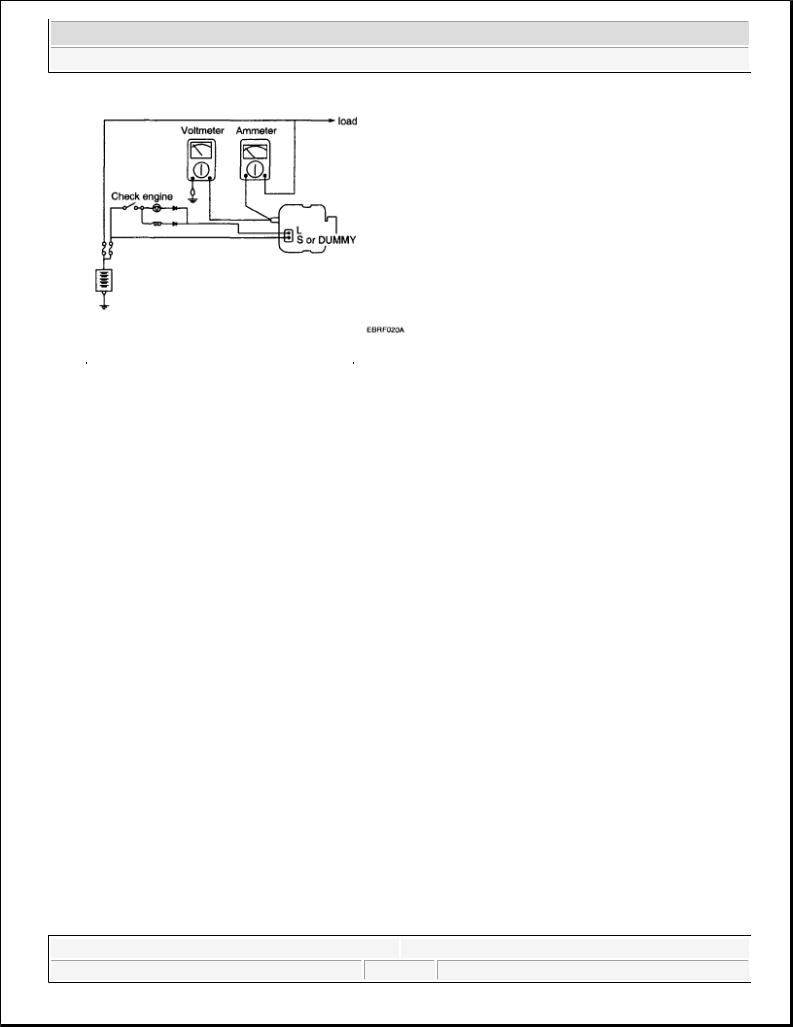
VOLTAGE DROP TEST OF GENERATOR OUTPUT WIRE
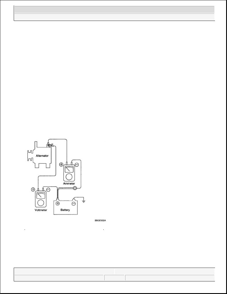
This test determines whether or not the wiring between the generator "B" terminal and the battery (+) terminal is good by the voltage drop method.
PREPARATION
1.Turn the ignition switch to "OFF".
2.Disconnect the output wire from the generator "B" terminal. Connect the (+) lead wire of ammeter to the "B" terminal of generator and the (-) lead wire of ammeter to the output wire. Connect the (+) lead wire of voltmeter to the "B" terminal of generator and the (-) lead wire of voltmeter to the (+) terminal of battery.
Fig. 3: Charging System Circuit Diagram
Courtesy of KIA MOTORS AMERICA, INC.
TEST
1.Start the engine.
2.Turn on the headlamps and blower motor, and set the engine speed until the ammeter indicates 20A.
Microsoft |
|
|
Saturday, May 22, 2010 4:06:11 PM |
Page 3 |
© 2006 Mitchell Repair Information Company, LLC. |

2008 Kia Sedona
2008 ELECTRICAL Charging System - Sedona
And then, read the voltmeter at this time.
RESULT
1.The voltmeter may indicate the standard value. Standard value: 0.2V max
2.If the value of the voltmeter is higher than expected (above 0.2V max.), poor wiring is suspected. In this case check the wiring from the alternator "B" terminal to the battery (+) terminal. Check for loose connections, color change due to an overheated harness, etc. Correct them before testing again.
3.Upon completion of the test, set the engine speed at idle.
Turn off the headlamps, blower motor and the ignition switch.
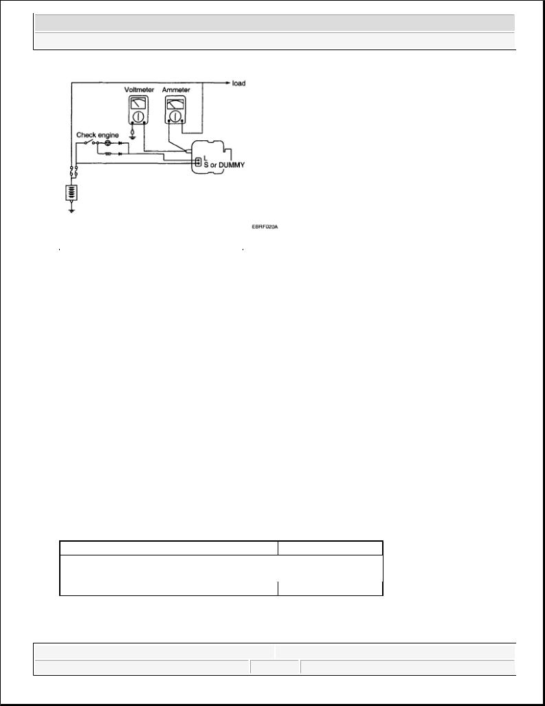
OUTPUT CURRENT TEST
This test determines whether or not the generator gives an output current that is equivalent to the normal output.
PREPARATION
1.Prior to the test, check the following items and correct as necessary.
Check the battery installed in the vehicle to ensure that it is in good condition. The battery checking method is described in BATTERY.
The battery that is used to test the output current should be one that has been partially discharged. With a fully charged battery, the test may not be conducted correctly due to an insufficient load.
Check the tension of the generator drive belt. The belt tension check method is described in INSPECT DRIVE BELT.
2.Turn off the ignition switch.
3.Disconnect the battery ground cable.
4.Disconnect the generator output wire from the alternator "B" terminal.
5.Connect a DC ammeter (0 to 150A) in series between the "B" terminal and the disconnected output wire. Be sure to connect the (-) lead wire of the ammeter to the disconnected output wire.
NOTE: |
Tighten each connection securely, as a heavy current will flow. Do not rely |
|
on clips. |
6.Connect a voltmeter (0 to 20V) between the "B" terminal and ground. Connect the (+) lead wire to the alternator "B" terminal and (-) lead wire to a good ground.
7.Attach an engine tachometer and connect the battery ground cable.
8.Leave the engine hood open.
Microsoft |
|
|
Saturday, May 22, 2010 4:06:11 PM |
Page 4 |
© 2006 Mitchell Repair Information Company, LLC. |
2008 Kia Sedona
2008 ELECTRICAL Charging System - Sedona
Fig. 4: Output Current Circuit Diagram
Courtesy of KIA MOTORS AMERICA, INC.
TEST
1.Check to see that the voltmeter reads as the same value as the battery voltage. If the voltmeter reads 0V, and the open circuit in the wire between alternator "B" terminal and battery (-) terminal or poor grounding is suspected.
2.Start the engine and turn on the headlamps.
3.Set the headlamps to high beam and the heater blower switch to HIGH, quickly increase the engine speed to 2,500 RPM and read the maximum output current value indicated by the ammeter.
NOTE: |
After the engine start up, the charging current quickly drops. |
|
Therefore, the above operation must be done quickly to read the maximum |
|
current value correctly. |
RESULT
1.The ammeter reading must be higher than the limit value. If it is lower but the generator output wire is in good condition, remove the generator from the vehicle and test it.
Limit value: 91A min. (130A alternator)
NOTE: |
The nominal output current value is shown on the nameplate affixed |
|
to the generator body. |
|
The output current value changes with the electrical load and the |
|
temperature of the generator itself. |
|
The nominal output current may not be obtained if the temperature of |
|
the generator itself or ambient temperature is too high. |
Microsoft |
|
|
Saturday, May 22, 2010 4:06:11 PM |
Page 5 |
© 2006 Mitchell Repair Information Company, LLC. |

2008 Kia Sedona
2008 ELECTRICAL Charging System - Sedona
In such a case, reduce the temperature before testing again.
2.Upon completion of the output current test, lower the engine speed to idle and turn off the ignition switch.
3.Disconnect the battery ground cable.
4.Remove the ammeter and voltmeter and the engine tachometer.
5.Connect the generator output wire to the generator "B" terminal.
6.Connect the battery ground cable.
REGULATED VOLTAGE TEST
The purpose of this test is to check that the electronic voltage regulator controls voltage correctly.
PREPARATION
1.Prior to the test, check the following items and correct if necessary.
Check that the battery installed on the vehicle is fully charged. The battery checking method is described in BATTERY.
Check the alternator drive belt tension. The belt tension check method is described in INSPECT DRIVE BELT.
2.Turn ignition switch to "OFF".
3.Disconnect the battery ground cable.
4.Connect a digital voltmeter between the "B" terminal of the alternator and ground. Connect the (+) lead of the voltmeter to the "B" terminal of the alternator. Connect the (-) lead to good ground or the battery (-) terminal.
5.Disconnect the alternator output wire from the alternator "B" terminal.
6.Connect a DC ammeter (0 to 150A) in series between the "B" terminal and the disconnected output wire. Connect the (-) lead wire of the ammeter to the disconnected output wire.
7.Attach the engine tachometer and connect the battery ground cable.
Microsoft |
|
|
Saturday, May 22, 2010 4:06:11 PM |
Page 6 |
© 2006 Mitchell Repair Information Company, LLC. |
2008 Kia Sedona
2008 ELECTRICAL Charging System - Sedona
Fig. 5: Output Current Circuit Diagram
Courtesy of KIA MOTORS AMERICA, INC.
TEST
1.Turn on the ignition switch and check to see that the voltmeter indicates the following value. Voltage: Battery voltage
If it reads 0V, there is an open circuit in the wire between the generator "B" terminal and the battery and the battery (-) terminal.
2.Start the engine. Keep all lights and accessories off.
3.Run the engine at a speed of about 2,500 RPM and read the voltmeter when the generator output current drops to 10A or less
RESULT
1.If the voltmeter reading agrees with the value listed in the regulating voltage table below, the voltage regulator is functioning correctly. If the reading is other than the standard value, the voltage regulator or the alternator is faulty.
REGULATING VOLTAGE TABLE
REGULATING VOLTAGE CHART
Voltage regulator ambient temperature °C (°F) Regulating voltage (V)
-30 |
(-22) |
14.2-15.3 |
25 |
(77) |
14.2-14.8 |
135 |
(275) |
13.3-14.8 |
2.Upon completion of the test, reduce the engine speed to idle, and turn off the ignition switch.
3.Disconnect the battery ground cable.
Microsoft |
|
|
Saturday, May 22, 2010 4:06:11 PM |
Page 7 |
© 2006 Mitchell Repair Information Company, LLC. |
2008 Kia Sedona
2008 ELECTRICAL Charging System - Sedona
4.Remove the voltmeter and ammeter and the engine tachometer.
5.Connect the generator output wire to the generator "B" terminal.
6.Connect the battery ground cable.
ALTERNATOR
REMOVAL
1.Disconnect the battery negative terminal first, then the positive terminal.
2.Disconnect the alternator connector, and remove the cable from alternator "B" terminal.
3.Remove the drive belt.
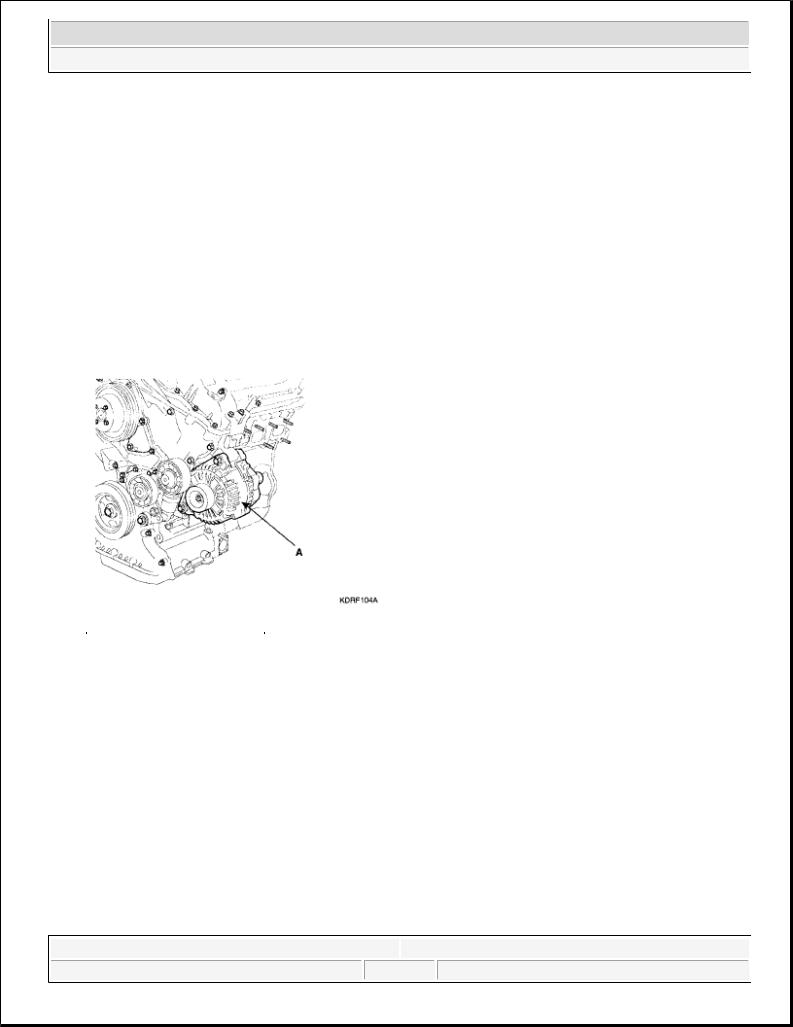
4.Pull out the through bolts and then remove the alternator (A).
Fig. 6: Locating Generator
Courtesy of KIA MOTORS AMERICA, INC.
5. Installation is the reverse of removal.
COMPONENT
Microsoft |
|
|
Saturday, May 22, 2010 4:06:11 PM |
Page 8 |
© 2006 Mitchell Repair Information Company, LLC. |
2008 Kia Sedona
2008 ELECTRICAL Charging System - Sedona
Fig. 7: Exploded View Of Generator
Courtesy of KIA MOTORS AMERICA, INC.
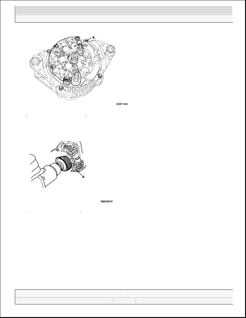
DISASSEMBLY
1. Remove the generator cover (A) using a screwdriver (B).
Microsoft |
|
|
Saturday, May 22, 2010 4:06:11 PM |
Page 9 |
© 2006 Mitchell Repair Information Company, LLC. |
2008 Kia Sedona
2008 ELECTRICAL Charging System - Sedona
Fig. 8: Identifying Generator Cover
Courtesy of KIA MOTORS AMERICA, INC.
2.Remove the slip ring guide (A).
3.Loosen the mounting bolts (B) and disconnect the brush holder assembly (C).
Fig. 9: Identifying Slip Ring Guide And Mounting Bolts
Courtesy of KIA MOTORS AMERICA, INC.
4. Remove the rectifier (A) with 4 screw.
Microsoft |
|
|
Saturday, May 22, 2010 4:06:11 PM |
Page 10 |
© 2006 Mitchell Repair Information Company, LLC. |
2008 Kia Sedona
2008 ELECTRICAL Charging System - Sedona
Fig. 10: Identifying Rectifier
Courtesy of KIA MOTORS AMERICA, INC.
5. Remove the nut, pulley (A) and spacer.
Fig. 11: Identifying Pulley
Courtesy of KIA MOTORS AMERICA, INC.
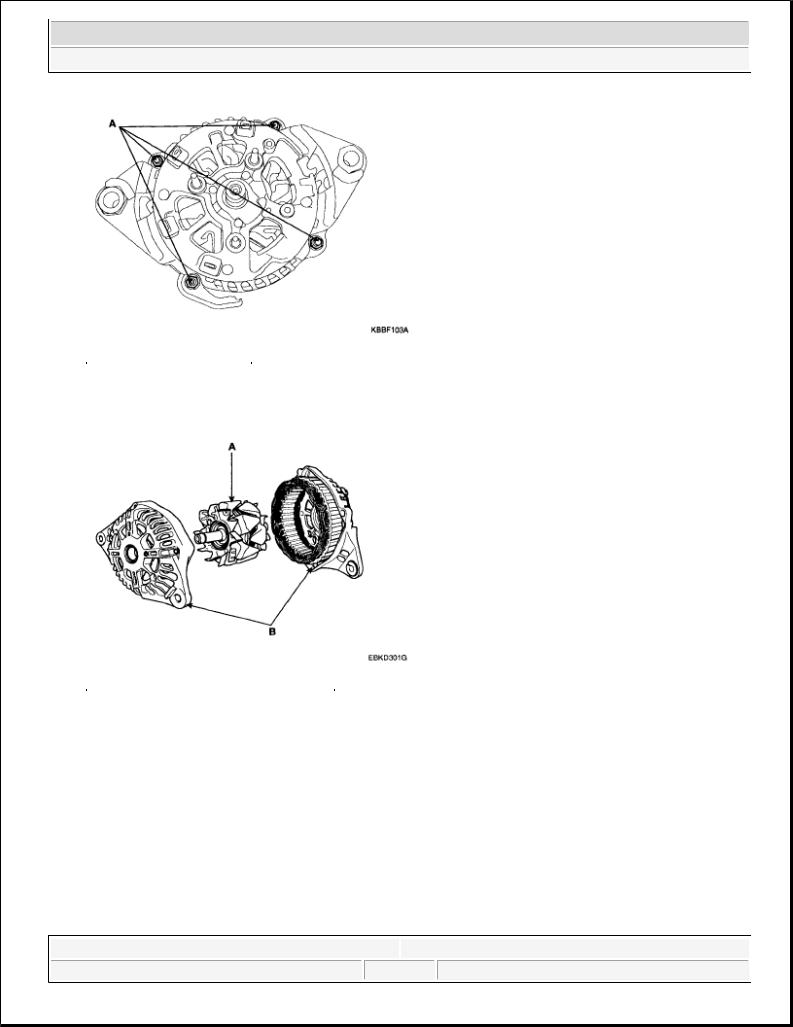
6. Loosen the 4 nuts (A).
Microsoft |
|
|
Saturday, May 22, 2010 4:06:11 PM |
Page 11 |
© 2006 Mitchell Repair Information Company, LLC. |
2008 Kia Sedona
2008 ELECTRICAL Charging System - Sedona
Fig. 12: Identifying Bolts
Courtesy of KIA MOTORS AMERICA, INC.
7. Disconnect the rotor (A) and cover (B).
Fig. 13: Identifying Rotor And Cover
Courtesy of KIA MOTORS AMERICA, INC.
8. Reassembly is the reverse order of disassembly.
INSPECTION
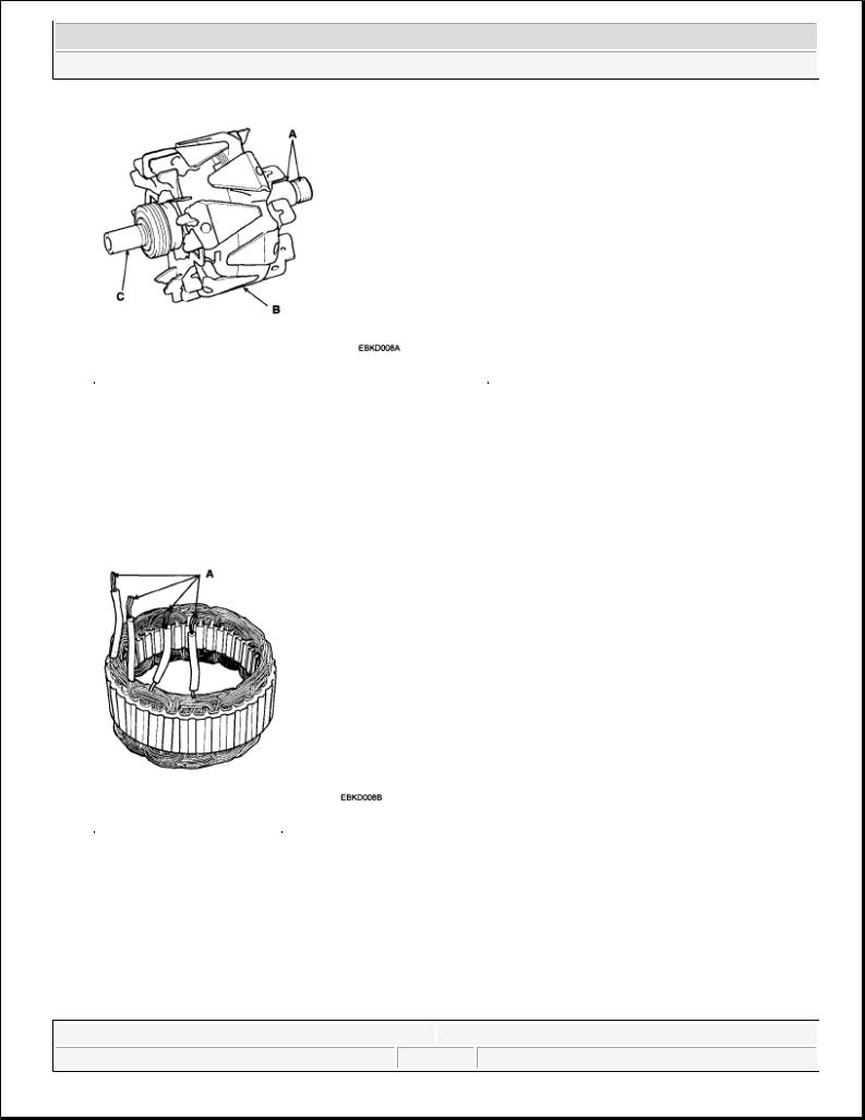
INSPECT ROTOR
1. Check that there is continuity between the slip rings (A).
Microsoft |
|
|
Saturday, May 22, 2010 4:06:11 PM |
Page 12 |
© 2006 Mitchell Repair Information Company, LLC. |
2008 Kia Sedona
2008 ELECTRICAL Charging System - Sedona
Fig. 14: Identifying Slip Rings, Rotor And Rotor Shaft
Courtesy of KIA MOTORS AMERICA, INC.
2.Check that there is no continuity between the slip rings and the rotor (B) or rotor shaft (C).
3.If the rotor fails either continuity check, replace the generator.
INSPECT STATOR
1. Check that there is continuity between each pair of leads (A).
Fig. 15: Identifying Leads
Courtesy of KIA MOTORS AMERICA, INC.
2.Check that there is no continuity between each lead and the coil core.
3.If the coil fails either continuity check, replace the alternator.
BATTERY
DESCRIPTION
Microsoft |
|
|
Saturday, May 22, 2010 4:06:11 PM |
Page 13 |
© 2006 Mitchell Repair Information Company, LLC. |
2008 Kia Sedona
2008 ELECTRICAL Charging System - Sedona
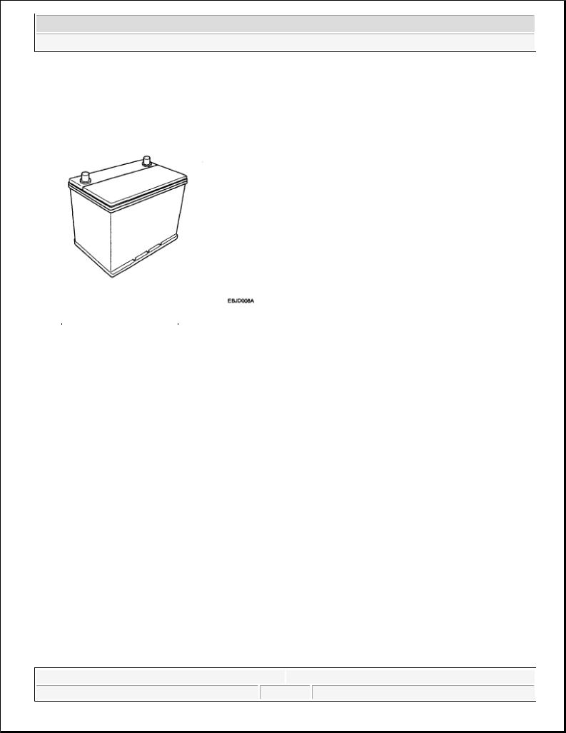
1.The maintenance-free battery is, as the name implies, totally maintenance free and has no removable battery cell caps.
2.Water never needs to be added to the maintenance-free battery.
3.The battery is completely sealed, except for small vent holes in the cover.
Fig. 16: View Of Battery
Courtesy of KIA MOTORS AMERICA, INC.
INSPECTION
BATTERY DIAGNOSTIC TEST (1)
CHECKING FLOW
Microsoft |
|
|
Saturday, May 22, 2010 4:06:11 PM |
Page 14 |
© 2006 Mitchell Repair Information Company, LLC. |
2008 Kia Sedona
2008 ELECTRICAL Charging System - Sedona
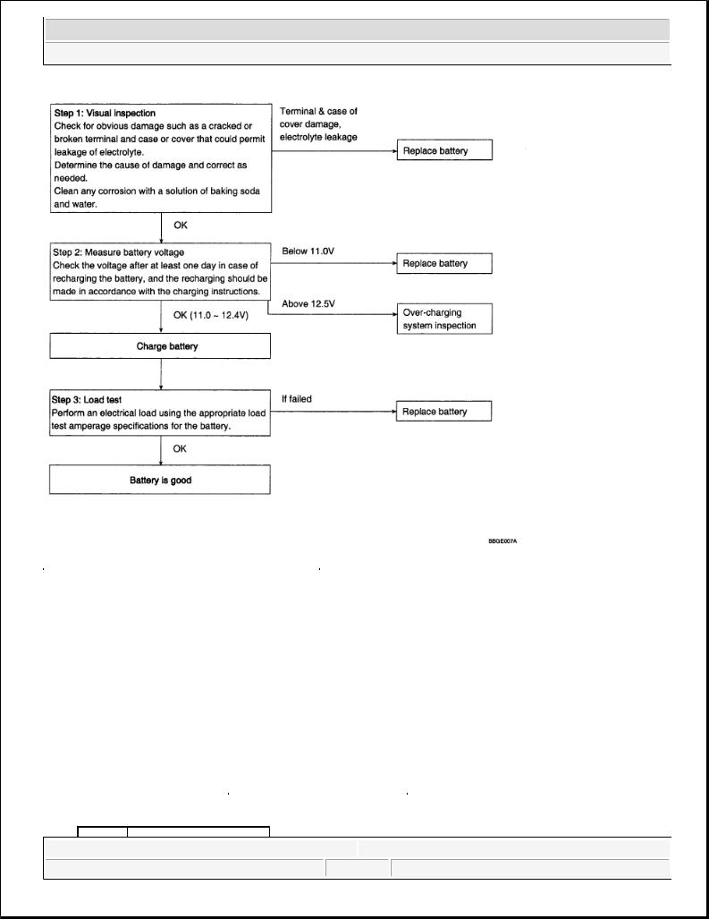
Fig. 17: Battery Diagnostic Test Flow Diagram
Courtesy of KIA MOTORS AMERICA, INC.
LOAD TEST
1.Perform the following steps to complete the load test procedure for maintenance free batteries.
2.Connect the load tester clamps to the terminals and proceed with the test as follow:
1.If the battery has been on charge, remove the surface charge by connecting a 300 ampere load for 15 seconds.
2.Connect the voltmeter and apply the specified load.
3.Read the voltage after the load has been applied for 15 seconds.
4.Disconnect the load.
5.Compare the voltage reading with the minimum and replace the battery if battery test voltage is below that shown in BATTERY TEST VOLTAGE.
BATTERY TEST VOLTAGE
Microsoft |
|
|
Saturday, May 22, 2010 4:06:11 PM |
Page 15 |
© 2006 Mitchell Repair Information Company, LLC. |
|
|
|
|
|
|
|
|
2008 Kia Sedona |
|
||
|
|
|
|||
|
|
2008 ELECTRICAL Charging System - Sedona |
|
||
|
|
|
|
|
|
|
Voltage |
Temperature |
|||
|
9.6V |
20°C (68.0°F) and above |
|||
|
9.5V |
16°C (60.8°F) |
|||
|
9.4V |
10°C (50.0°F) |
|||
|
9.3V |
4°C (39.2°F) |
|||
|
9.1V |
-1°C (30.2°F) |
|||
|
8.9V |
-7°C (19.4°F) |
|||
|
8.7V |
-12°C (10.4°F) |
|||
|
8.5V |
-18°C (-0.4°F) |
|||
|
NOTE: |
If the voltage is greater than shown in BATTERY TEST VOLTAGE, the |
|||
|
|
battery is good. |
|
|
|
If the voltage is less than shown in BATTERY TEST VOLTAGE, replace the battery.
BATTERY DIAGNOSTIC TEST (2)
1.Make sure the ignition switch and all accessories are in the OFF position.
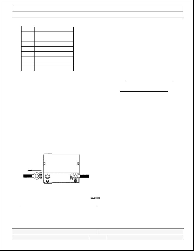
2.Disconnect the battery cables (negative first).
3.Remove the battery from the vehicle.
CAUTION: Care should be taken in the event the battery case is cracked or leaking, to protect your skin from the electrolyte.
Heavy rubber gloves (not the household type) should be wore when removing the battery.
Fig. 18: Disconnecting Negative Battery Cable
Courtesy of KIA MOTORS AMERICA, INC.
4.Inspect the battery tray for damage caused by the loss of electrolyte. If acid damage is present, it will be necessary to clean the area with a solution of clean warm water and baking soda. Scrub the area with a stiff brush and wipe off with a cloth moistened with baking soda and water.
Microsoft |
|
|
Saturday, May 22, 2010 4:06:11 PM |
Page 16 |
© 2006 Mitchell Repair Information Company, LLC. |
2008 Kia Sedona
2008 ELECTRICAL Charging System - Sedona
5.Clean the top of the battery with the same solution as described above.
6.Inspect the battery case and cover for cracks. If cracks are present, the battery must be replaced.
7.Clean the battery posts with a suitable battery post tool.
8.Clean the inside surface of the terminal clamps with a suitable battery cleaning tool. Replace damaged or frayed cables and broken terminal clamps.
9.Install the battery in the vehicle.
10.Connect the cable terminals to the battery post, making sure tops of the terminals are flush with the tops of the posts.
11.Tighten the terminal nuts securely.
12.Coat all connections with light mineral grease after tightening.
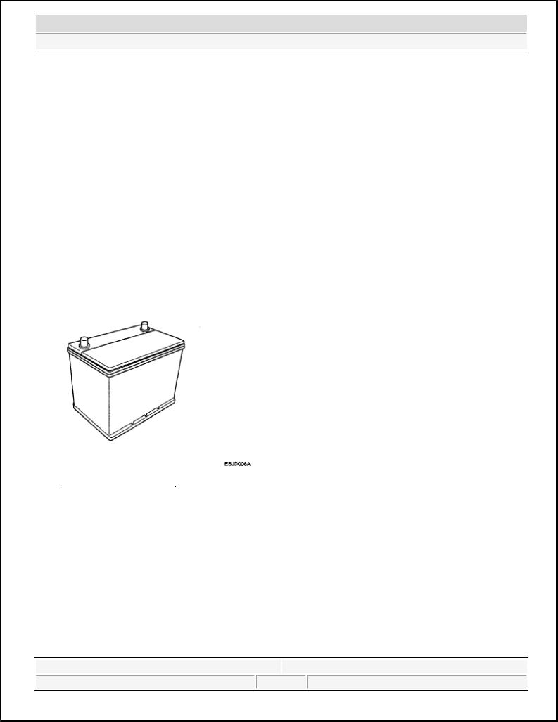
CAUTION: When batteries are being charged, an explosive gas forms beneath the cover of each cell. Do not smoke near batteries being charged or which have recently been charged. Do not break live circuit at the terminals of batteries being charged. A spark will occur when the circuit is broken. Keep open flames away from battery.
Fig. 19: View Of Battery
Courtesy of KIA MOTORS AMERICA, INC.
Microsoft |
|
|
Saturday, May 22, 2010 4:06:11 PM |
Page 17 |
© 2006 Mitchell Repair Information Company, LLC. |

2008 Kia Sedona
2008 ACCESSORIES & BODY, CAB Interior - Sedona
CRASH PAD
COMPONENTS
Fig. 7: Identifying Crash Pad Components
Courtesy of KIA MOTORS AMERICA, INC.
REPLACEMENT
CLUSTER FASCIA PANEL REPLACEMENT
|
NOTE: |
When prying with a flat-tipped screwdriver, wrap it with protective tape, |
||||||
|
|
and apply protective tape around the related parts, to prevent damage. |
||||||
|
|
|
|
|
|
|
|
|
|
|
|
|
|
|
|
|
|
|
Microsoft |
|
|
|
|
|
|
|
|
|
|
|
© 2006 Mitchell Repair Information Company, LLC. |
||||
|
Saturday, May 22, 2010 6:56:152 PM |
|
Page 1 |
|||||
|
|
|
|
|
|
|
|
|
2008 Kia Sedona
2008 ACCESSORIES & BODY, CAB Interior - Sedona
Put on gloves to protect your hands.
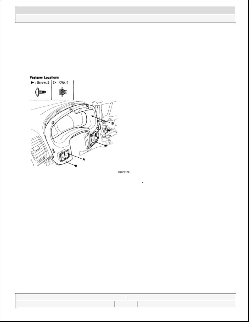
1.Tilt the steering column down.
2.Remove the screws, and detach the clips.
3.After disconnecting the connector (A), remove the cluster fascia panel (B).
Fig. 8: Identifying Connector And Cluster Fascia Panel
Courtesy of KIA MOTORS AMERICA, INC.
4. Installation is the reverse of removal.
NOTE: |
Make sure the connector is plugged in properly. |
CENTER FASCIA PANEL REPLACEMENT |
|
NOTE: |
When prying with a flat-tipped screwdriver, wrap it with protective tape, |
|
and apply protective tape around the related parts, to prevent damage. |
Put on gloves to protect your hands.
1.Detach the clips, then remove the center fascia panel (A).
Microsoft |
|
|
Saturday, May 22, 2010 6:56:12 PM |
Page 2 |
© 2006 Mitchell Repair Information Company, LLC. |
 Loading...