


 Loading...
TK-5730
TK-5830
TK-5930
USER GUIDE
GUIDE DE L'UTILISATEUR
GUÍA DEL USUARIO
B5A-0953-00 (K)

VHF DIGITAL TRANSCEIVER
TK-5730
UHF DIGITAL TRANSCEIVER
TK-5830
700/800MHz DIGITAL TRANSCEIVER
TK-5930
USER GUIDE
This User Guide covers only the basic operations of your radio. Ask your dealer for information on any customized features they may have added to your radio. For using details instruction manual (User Manual), refer to the following URL.
http://manual2.jvckenwood.com/en_contents/search/
•SDTM and microSDTM are trademarks of SD-3C, LLC in the United States. and/ or other countries.
•The Bluetooth® word mark and logos are registered trademarks owned by Bluetooth SIG, Inc. and any use of such marks by JVC KENWOOD
Corporation is under license. Other trademarks and trade names are those of their respective owners.

THANK YOU |
|
We are grateful you have chosen KENWOOD for your Digital Transceiver |
|
applications. |
|
CONTENTS |
|
NOTICES TO THE USER ................................................................ |
3 |
PRECAUTIONS .......................................................................... |
4 |
TERMINAL DESCRIPTIONS............................................................ |
5 |
PREPARATION .......................................................................... |
6 |
ORIENTATION ........................................................................... |
9 |
OPERATION PANEL (OPTIONAL KCH-19)..................................................... |
9 |
DISPLAY ..................................................................................................... |
10 |
BASIC OPERATION ................................................................... |
13 |
SWITCHING POWER ON/ OFF..................................................................... |
13 |
ADJUSTING THE VOLUME.......................................................................... |
13 |
SELECTING A ZONE AND CHANNEL........................................................... |
13 |
TRANSMITTING.......................................................................................... |
13 |
RECEIVING ................................................................................................. |
13 |
INFORMATION ON SOFTWARE LICENSE .......................................... |
14 |
2

NOTICES TO THE USER
•Government law prohibits the operation of unlicensed radio transmitters within the territories under government control.
•Illegal operation is punishable by fi ne and/or imprisonment.
•Refer service to qualifi ed technicians only.
Safety: It is important that the operator is aware of, and understands, hazards common to the operation of any transceiver.
•EXPLOSIVE ATMOSPHERES (GASES, DUST, FUMES, etc.)
Turn OFF your transceiver while taking on fuel or while parked in gasoline service stations. Do not carry spare fuel containers in the trunk of your vehicle if your transceiver is mounted in the trunk area.
•INJURY FROM RADIO FREQUENCY TRANSMISSIONS
Do not operate your transceiver when somebody is either standing near to or touching the antenna, to avoid the possibility of radio frequency burns or related physical injury.
•DYNAMITE BLASTING CAPS
Operating the transceiver within 500 feet (150 m) of dynamite blasting caps may cause them to explode. Turn OFF your transceiver when in an area where blasting is in progress, or where “TURN OFF TWO-WAY RADIO” signs have been posted. If you are transporting blasting caps in your vehicle, make sure they are carried in a closed metal box with a padded interior. Do not transmit while the caps are being placed into or removed from the container.
One or more of the following statements may be applicable:
FCC WARNING
This equipment generates or uses radio frequency energy. Changes or modifications to this equipment may cause harmful interference unless the modifications are expressly approved by the party responsible/ JVC KENWOOD. The user could lose the authority to operate this equipment if an unauthorized change or modification is made.
INFORMATION TO THE DIGITAL DEVICE USER REQUIRED BY THE FCC
This equipment has been tested and found to comply with the limits for a Class B digital device, pursuant to Part 15 of the FCC Rules. These limits are designed to provide reasonable protection against harmful interference in a residential installation.
This equipment generates, uses and can generate radio frequency energy and, if not installed and used in accordance with the instructions, may cause harmful interference to radio communications. However, there is no guarantee that the interference will not occur in a particular installation. If this equipment does cause harmful interference to radio or television reception, which can be determined by turning the equipment off and on, the user is encouraged to try to correct the interference by one or more of the following measures:
•Reorient or relocate the receiving antenna.
•Increase the separation between the equipment and receiver.
•Connect the equipment to an outlet on a circuit different from that to which the receiver is connected.
•Consult the dealer for technical assistance.
3
The AMBE+2TM voice coding Technology embodied in this product is protected by intellectual property rights including patent rights, copyrights and trade secrets of Digital Voice Systems, Inc. This voice coding Technology is licensed solely for use within this Communications Equipment. The user of this Technology is explicitly prohibited from attempting to extract, remove, decompile, reverse engineer, or disassemble the Object Code, or in any other way convert the Object Code into a human-readable form. U.S. Patent Nos. #6,199,037, #6,912,495, #8,200,497, #7,970,606, and #8,359,197.
Firmware Copyrights
The title to and ownership of copyrights for firmware embedded in KENWOOD product memories are reserved for JVC KENWOOD Corporation.
PRECAUTIONS
Observe the following precautions to prevent fi re, personal injury, and transceiver damage.
•Do not attempt to confi gure the transceiver while driving; it is too dangerous.
•Do not disassemble or modify the transceiver for any reason.
•Do not expose the transceiver to long periods of direct sunlight, nor place it near heating appliances.
•If an abnormal odor or smoke is detected coming from the transceiver, switch the transceiver power off immediately, and contact your KENWOOD dealer.
•Use of the transceiver while you are driving may be against traffi c laws. Please check and observe the vehicle regulations in your area.
•Do not use options not specifi ed by KENWOOD.
•Do not put the plastic bag used for packing of this equipment on the place which reaches a small child's hand. It will become a cause of suffocation if it wears fl atly.
•Do not place the transceiver on unstable surfaces.
•Keep the volume as low as possible to protect your hearing.
•Always switch the transceiver power off before installing optional accessories.
•To dispose of batteries, be sure to comply with the laws and regulations in your country or region.
•The transceiver operates in 12 V negative ground systems only! Check the battery polarity and voltage of the vehicle before installing the transceiver.
•Use only the supplied DC power cable or a KENWOOD optional DC power cable.
•Do not cut and/or remove the fuse holder on the DC power cable.
•Do not place the microphone cable around your neck while near machinery that may catch the cable.
For passenger safety, install the transceiver securely using the supplied mounting bracket and screw set so the transceiver will not break loose in the event of a collision.
When using the Transceiver, refer to the “NOTICES TO THE USER” and “PRECAUTIONS”. If the warnings are not observed, there may be the possibility to have any malfunction. In this case, press and hold the Power Switch for 5 seconds or more. If the malfunction persists, ask your dealer.
4

TERMINAL DESCRIPTIONS
ACC (D-SUB 25 Pin Connector)
Pin No. |
Name |
I/O |
Description |
Specification |
|
1 |
NC |
— |
Not used |
|
|
2 |
COM1_RXD |
I |
Serial Data Input |
RS-232C compatible |
|
3 |
COM1_TXD |
O |
Serial Data Output |
||
|
|||||
4 |
AUXI/O9 |
I/O |
Programmable Function I/O 9 |
Input Impedance 100 k |
|
Output Impedance 100 |
|||||
|
|
|
|
||
5 |
DI |
I |
Data Input |
0.5 V p-p (Typ.) |
|
Input Impedance 20 k |
|||||
|
|
|
|
||
|
|
|
|
5 mVrms(Typ.) |
|
6 |
MI2 |
I |
MIC Signal Input |
(STD Deviation) |
|
|
|
|
|
Input Impedance 600 |
|
7 |
GND |
— |
Ground |
Ground |
|
8 |
AUXI/O8 |
I/O |
Programmable Function I/O 8 |
Input Impedance 100 k |
|
Output Impedance 470 |
|||||
|
|
|
|
||
9 |
COM2_TXD |
O |
Serial Data Output |
TTL (0V - 5V) |
|
10 |
COM2_RXD |
I |
Serial Data Input |
||
|
|||||
11 |
GND |
— |
Ground |
Ground |
|
12 |
AUXI/O7/BER_DATA |
I/O |
Programmable Function I/O 7 |
Input Impedance 100 k |
|
13 |
AUXI/O6/BER_CLK |
I/O |
Programmable Function I/O 6 |
Output Impedance 100 |
|
|
|||||
|
|
|
|
||
14 |
SB |
O |
DC Power (Switched B) Output |
13.6 V ±15% |
|
2 A (Max) |
|||||
|
|
|
|
||
15 |
AUXO2 |
O |
Programmable Function O 2 |
Open Drain |
|
|
|
|
|
R (dc): 60 m (Max) |
|
16 |
AUXO1 |
O |
Programmable Function O 1 |
Idc (Max)= -500 mA |
|
|
|
|
|
|
|
17 |
AFO |
O |
AF Signal Output |
0.7 V p-p (Typ.) |
|
Output Impedance 100 |
|||||
|
|
|
|
||
18 |
GND |
— |
Ground |
Ground |
|
19 |
DEO |
O |
RX Detected Signal Output |
0.28 Vp-p (Typ.) |
|
Output Impedance 100 |
|||||
|
|
|
|
||
20 |
AUXI/O5 |
I/O |
Programmable Function I/O 5 |
|
|
|
|
|
|
|
|
21 |
AUXI/O4 |
I/O |
Programmable Function I/O 4 |
Input Impedance 100 k |
|
22 |
AUXI/O3 |
I/O |
Programmable Function I/O 3 |
Output Impedance 470 |
|
23 |
AUXI/O2 |
I/O |
Programmable Function I/O 2 |
|
|
24 |
AUXI/O1 |
I/O |
Programmable Function I/O 1 |
|
|
25 |
ME |
— |
Mic Ground |
Ground |
|
Speaker Jack (3.5 mm Phone Jack) 4 W/ 4 |
|
||||
|
|
|
|
|
|
Pin No. |
Name |
I/O |
Description |
Specification |
|
1 |
SPO |
O |
External Speaker Output |
4 (Min) |
|
3 |
GND |
— |
Ground |
Ground |
|
DC Input Connector |
|
|
|
||
|
|
|
|
|
|
Pin No. |
Name |
I/O |
Description |
Specification |
|
Red |
B |
I |
DC Power Input |
13.6 V ±15% |
|
Black |
GND |
— |
Ground |
Ground |
|
Ignition Sense Input Terminal |
|
|
|
||
Pin No. |
Name |
I/O |
Description |
Specification |
|
Yellow |
B |
I |
Ignition Sense Input |
13.6 V ±15% |
|
Microphone Jack (OPTIONAL KCH-19) |
|
|
|||
|
|
|
|
|
|
Pin No. |
Name |
I/O |
Description |
Specification |
|
1 |
BLC |
O |
Mic Backlight Control |
Output Impedance 1 k |
|
D+ |
I/O |
USB Serial Data I/O |
USB 2.0 |
||
|
|||||
2 |
SB |
O |
DC Power (Switched B) Output |
13.6 V ±15% |
|
200 mA (Max) |
|||||
|
|
|
|
||
3 |
GND |
— |
Ground |
Ground |
|
4 |
PTT |
I |
PTT |
Input Impedance 47 k |
|
TXD |
O |
PC Serial Data from Radio |
UART TTL (0V to 5V) |
||
|
|||||
5 |
ME |
— |
Mic Ground |
Ground |
|
6 |
MIC |
I |
Mic Signal Input |
Input Impedance 600 |
|
VBUS |
I |
USB VBUS |
5 V/ 1 mA (Typ.) |
||
|
|||||
|
HOOK |
I |
Hook |
Input Impedance 1 k |
|
7 |
RXD |
I |
PC Serial Data to Radio |
UART TTL (0V to 5V) |
|
|
D- |
I/O |
USB Serial Data I/O |
USB 2.0 |
|
8 |
DM |
I/O |
Mic Data Detection |
High Impedance |
|
RF Antenna Terminal
50 impedance
GPS Antenna Terminal
50 impedance
5
PREPARATION
■ Supplied accessorie
User guide . . . . . . . . . . . . . . . . . . . . . . . . . . . . . . . . . . . . . . . . . . . . . . . . . . . . . . . . . 1
Various electronic equipment in your vehicle may malfunction if they are not properly protected from the radio frequency energy which is present while transmitting. Typical examples include electronic fuel injection, anti-skid braking, and cruise control. If your vehicle contains such equipment, consult the dealer for the make of vehicle and enlist his/her aid in determining if they will perform normally while transmitting.
■ Connecting the power cable
The transceiver operates in 12 V negative ground systems only! Check the battery polarity and voltage of the vehicle before installing the transceiver.
1Check for an existing hole, conveniently located in the fi rewall, where the power cable can be passed through.
•If no hole exists, use a circle cutter to drill a hole, then install a rubber grommet.
2Run the power cable through the fi rewall and into the engine compartment.
3Connect the red lead to the positive (+) battery terminal and the black lead to the negative (–) battery terminal.
•Place the fuse as close to the battery as possible.
4Coil the surplus cable and secure it with a retaining band.
•Be sure to leave enough slack in the cables so the transceiver can be removed for servicing while keeping the power applied.
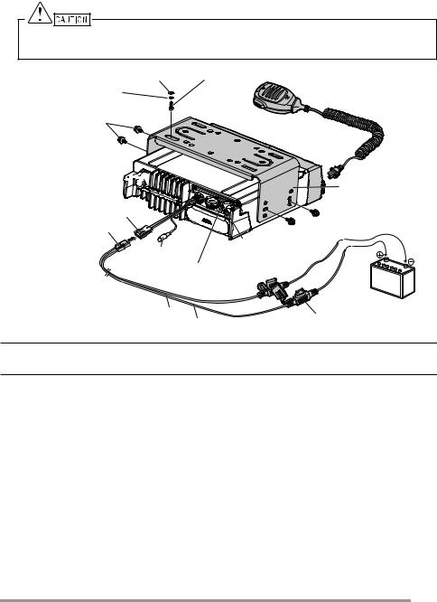
■Installing the Transceiver
For passenger safety, install the transceiver securely using the optional mounting bracket and screw set, so the transceiver will not break loose in the event of a collision.
Note:
•Before installing the transceiver, check how far the mounting screws will extend below the surface. When drilling mounting holes, be careful not to damage vehicle wiring or parts.
1Mark the position of the holes in the dash, using the mounting bracket as a template. Using a 4.2 mm (5/32 inch) drill bit, drill the holes, then attach the mounting bracket using the supplied screws.
•Mount the transceiver within easy reach of the user and where there is sufficient space at the rear of the transceiver for cable connections.
2Connect the antenna and the supplied power cable to the transceiver.
3Slide the transceiver into the mounting bracket and secure it using the supplied hex-headed screws.
6
4Mount the microphone hanger in a location where it will be within easy reach of the user.
•The microphone and microphone cable should be mounted in a place where they will not interfere with the safe operation of the vehicle.
When replacing the fuse in the DC power cable, be sure to replace it with a fuse of the same value. Never replace a fuse with one that is rated with a higher value.
Flat washer |
5 x 16 mm Self-tapping screw |
Spring washer |
Microphone |
M4 x 6 mm hex-headed screw with washer
RF antenna connector 


|
|
|
|
Mounting bracket |
|
Power input connector |
|
|
|
|
|
DC power cable |
|
|
|
|
|
Ignition sense |
GPS antenna connector |
|
|||
for KRA-40 |
|
|
|||
cable |
|
|
|
||
|
External |
|
|
||
|
|
|
|
||
|
|
speaker jack |
|
|
|
Black (–) cable |
|
|
|
12 V vehicle |
|
Red (+) cable |
Fuse |
battery |
|||
|
|||||
|
|
|
|||
Note:
•The items above shown in gray are optional accessories.
7

■ Using the microSD memory card
To install a microSD memory card on this transceiver, please consult your dealer.
•microSD memory cards (Class 2 or higher) and microSDHC memory cards (Class 2 or higher) can be used.
•SDXC memory cards cannot be used.
•This transceiver is not guaranteed to operate with all microSD memory cards. (Operations are confirmed on memory cards for the following brands: SanDisk, TOSHIBA and Panasonic.)
Compensation Disclaimer
Data stored on the microSD memory card may be altered or lost due to problems with this transceiver. We do not accept liability in respect of the data stored on your microSD memory card, failure to save the data properly, loss of data, and any direct or indirect damages.
8
|
|
|
|
|
|
|
|
|
|
|
|
|
|
|
|
|
|
|
|
|
|
|
ORIENTATION |
|
|
|
|
|
|
|
|
||||||||||||||
|
|
|
|
|
|
|
|
|
|
|
|
|
|
|
|
|
|
|
|
|
|
|
|
|
|
|
|
|
|
|
|
|
|
|
|
|
|
|
|
|
|
|
|
|
|
OPERATION PANEL (OPTIONAL KCH-19) |
|
|
|
|
|
|
|
|
|||||||||||||||||||||||||||||||||||||
|
|
|
|
|
a b |
|
c |
||||||||||||||||||||||||||||||||||||||
|
|
|
|
|
|
|
|
|
|
|
|
|
|
|
|
|
|
|
|
|
|
|
|
|
|
|
|
|
|
|
|
|
|
|
|
|
|
|
|
|
|
|
|
|
|
|
|
|
|
|
|
|
|
|
|
|
|
|
|
|
|
|
|
|
|
|
|
|
|
|
|
|
|
|
|
|
|
|
|
|
|
|
|
|
|
|
|
|
|
|
|
|
|
|
|
|
|
|
|
|
|
|
|
|
|
|
|
|
|
|
|
|
|
|
|
|
|
|
|
|
|
|
|
|
|
|
|
|
|
|
|
|
|
|
|
|
|
|
|
|
|
|
|
|
|
|
|
|
|
|
|
|
|
|
|
|
|
|
|
|
|
|
|
|
|
|
|
|
|
|
|
|
|
|
|
|
|
|
|
|
|
|
|
|
|
|
|
|
|
|
|
|
|
|
|
|
|
|
|
|
|
|
|
|
|
|
|
|
|
|
|
|
|
|
|
|
|
|
|
|
|
|
|
|
|
|
|
|
|
|
|
|
|
|
|
|
|
|
|
|
|
|
|
|
|
|
|
|
|
|
|
|
|
|
|
|
|
|
|
|
|
|
|
|
|
|
|
|
|
|
|
|
|
|
|
|
|
|
|
|
|
|
|
|
|
|
|
|
|
|
|
|
|
|
|
|
|
|
|
|
|
|
|
|
|
|
|
|
|
|
|
|
|
|
|
|
|
|
|
|
|
|
|
|
|
|
|
|
|
|
|
|
|
|
|
|
|
|
|
|
|
|
|
|
|
|
|
|
|
|
|
|
|
|
|
|
|
|
|
|
|
|
|
|
|
|
|
|
|
|
|
|
|
|
|
|
|
|
|
|
|
|
|
|
|
|
|
|
|
|
|
|
|
|
|
|
|
|
|
|
|
|
|
|
|
|
|
|
|
|
|
|
|
|
|
|
|
|
|
|
|
|
|
|
|
|
|
|
|
|
|
|
|
|
|
|
|
|
|
|
|
|
|
|
|
|
|
|
|
|
|
|
|
|
|
|
|
|
|
|
|
|
|
|
|
|
|
|
|
|
|
|
|
|
|
|
|
|
|
|
|
|
|
|
|
|
|
|
|
|
|
|
|
|
|
|
|
|
|
|
|
|
|
|
|
|
|
|
|
|
|
|
|
|
|
|
|
|
|
|
|
|
|
|
|
|
|
|
|
|
|
|
|
|
|
|
|
|
|
|
|
|
|
|
|
|
|
|
|
|
|
|
|
|
|
|
|
|
|
|
|
|
|
|
|
|
|
|
|
|
|
|
|
|
|
|
|
|
|
|
|
|
|
|
|
|
|
|
|
|
|
|
|
|
|
|
|
d e f |
g |
h |
a[ ] (Power) switch
Press to switch the transceiver ON or OFF.
b[ ] / [ ] keys
Press to activate its programmable function. The default key setting is
[Volume Up]/ [Volume Down].
c[ ] / [
] / [ ] keys
Press to activate its programmable function. The default key setting is
[Channel Up]/ [Channel Down].
dIllumination sensor
Sensor for Auto Dimmer Function.
eMicrophone jack
Insert the microphone plug into this jack.
fTX/RX Indicator
The indicator lights in different colors to indicate the current status of the transceiver.
Lights red while transmitting and green while receiving.
g[ ] / [
] / [ ] / [
] / [ ] / [
] / [ ] / [
] / [ ] / [
] / [ ] / Auxiliary (orange) keys
Press to activate their programmable functions.
[ ] : The default key setting is [Clear]. [
 ] : The default key setting is [Menu].
[ ] : The default key setting is [Squelch Off Momentary]. [
 ] : The default key setting is [Zone Down].
[ ] : The default key setting is [Zone Up]. [
 ] : The default key setting is [Function].
Auxiliary (orange) : The default key setting is [None].
hSpeaker
Internal speaker.
For details on programming functions to the keys on your transceiver, please contact your dealer or refer to the "User Manual" available from the following URL.
http://manual2.jvckenwood.com/en_contents/search/
9
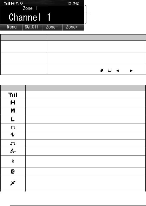
DISPLAY
Basic Frame
 Function Indicator Area
Main Area
 Key Guide Area
Display Area |
Description |
Function Indicator Area
Displays the various function indicators, signal strength indicator and clock.
Main Area
Display the information of the transceiver such as
Channel number and Zone number.
Key Guide Area |
Display the key functions for [ ], [ ], [ ] and [ ] keys. |
Function Indicator
Indicator |
Description |
|
Displays the signal strength. |
The channel is using high transmit power.
The channel is using medium transmit power.
The channel is using low transmit power.
In Digital mode (Digital Channel)
In Analog mode (Analog Channel)
In Digital mode (Mixed Channel)
In Analog mode (Mixed Channel)
The Bluetooth function is activated. Blinks in the process of turning on Bluetooth.
Connected to Bluetooth device.
The GPS position is determined. Blinks when the GPS is unable to determine the position.
10

Indicator |
Description |
Non-priority Scan or Voting/Site Roaming is in progress.
Blinks when the scan is paused. (green icon)
Priority Scan is in progress.
Blinks when the scan is paused. (red icon)
Indicates Priority channel 1 or Priority Monitor ID 1.
Indicates Priority channel 2 or Priority Monitor ID 2.
Indicates Priority Monitor ID 3.
Indicates Priority Monitor ID 4.
The current channel is added to the scanning sequence.
The current Zone is added to the Multi-Zone scanning sequence.
The Scrambler function is activated.
The Encryption function is activated. Blinks when receiving an encrypted carrier.
The Encryption (AES) function is activated. Blinks when receiving an encrypted carrier.
The Encryption (DES) function is activated. Blinks when receiving an encrypted carrier.
The Talk Around function is activated.
The Monitor or Squelch Off is activated.
The External Speaker is activated.
The External Speaker (Internal + External) is activated.
The Noise Reduction function is activated. Blinks when Noise Reduction is functioning.
Blinks when an incoming call matches your Optional Signaling.
A message is stored in the memory. Blinks when a new message is received.
The microSD memory card is recognized.
The microSD memory card is not recognized.
The VOX function is activated.
11
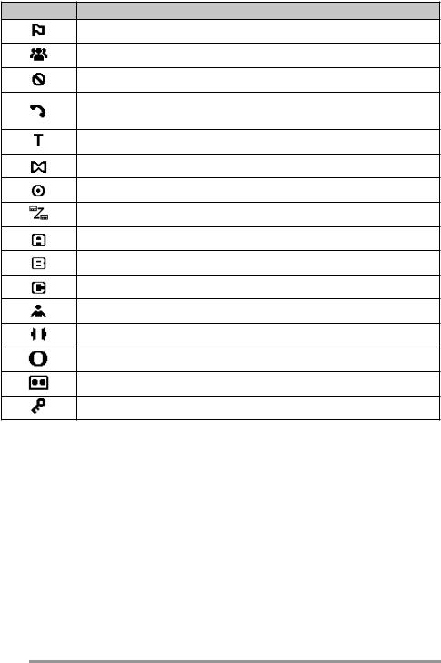
Indicator |
Description |
The Site Lock function is activated.
The Broadcast Call function is activated.
The Surveillance function is activated.
The selected group is programmed as telephone IDs. Blinks during Auto Telephone search.
The Tactical Zone is activated.
The Horn Alert function is activated.
The Public Address function is activated.
The Intercom function is activated.
AUX A is activated.
AUX B is activated.
AUX C is activated.
The Lone Worker function is activated.
The Compander function is activated.
The Operator Selectable Tone function is activated.
Blinks during Auto Recording.
The Key Lock function is activated.
12

BASIC OPERATION
SWITCHING POWER ON/ OFF
Press [ ] to switch the transceiver ON.
Press [ ] again to switch the transceiver OFF.
ADJUSTING THE VOLUME
Press the key programmed as [Volume Up] to increase the volume. Press the key programmed as [Volume Down] to decrease the volume.
SELECTING A ZONE AND CHANNEL
Select the desired zone and channel using the keys programmed as [Zone Up]/
[Zone Down] and [Channel Up]/ [Channel Down].
•The transceivers may have names programmed for zones and channels. The zone name and channel name can contain up to 16 and 14 characters respectively. While selecting a zone, the zone name will appear above the channel name.
•If programmed by your dealer, your transceiver will announce the zone and channel numbers as you change them.
TRANSMITTING
1Select the desired zone and channel.
2Press the PTT switch and speak into the microphone. Release the PTT switch to receive.
•The LED indicator lights red while transmitting and green while receiving a signal. This indicator can also be disabled by your dealer.
•For best sound quality at the receiving station, hold the microphone approximately 1.5 inches (3 cm to 4 cm) from your mouth.
RECEIVING
Select the desired zone and channel. If signaling has been programmed on the selected channel, you will hear a call only if the received signal matches your transceiver settings.
13
Loading...