


 Loading...
TH-D74A
TH-D74E
User MAnUAL
This User Manual covers detailed operating instructions of the TH-D74A/E including basic operating instructions described in the User Guide comes with the product.
B5A-1253-00/04

 1 CONTENTS
1 CONTENTS............................................................ |
1 |
2 BEFORE STARTING................................................ |
2-1 |
3 PREPARATION...................................................... |
3-1 |
SUPPLIED ACCESSORIES................................................................ |
3-1 |
INSTALLING THE ANTENNA............................................................. |
3-1 |
INSTALLING THE BATTERY PACK.................................................... |
3-1 |
INSTALLING ALKALINE BATTERIES................................................. |
3-1 |
INSTALLING THE BELT CLIP............................................................ |
3-2 |
INSTALLING THE HAND STRAP....................................................... |
3-2 |
CHARGING THE BATTERY PACK...................................................... |
3-2 |
BATTERY LIFE.................................................................................. |
3-3 |
CONNECTING TO A CIGARETTE LIGHTER SOCKET......................... |
3-3 |
CONNECTING TO A REGULATED POWER SUPPLY.......................... |
3-3 |
4 GETTING ACQUAINTED........................................... |
4-1 |
KEY AND CONTROL KNOB OPERATIONS........................................ |
4-1 |
DISPLAY.......................................................................................... |
4-3 |
5 BASIC OPERATIONS............................................... |
5-1 |
SWITCHING THE POWER ON/ OFF.................................................. |
5-1 |
ADJUSTING THE INTERNAL CLOCK................................................ |
5-1 |
ADJUSTING THE VOLUME............................................................... |
5-1 |
VOLUME BALANCE (BAND A/B)....................................................... |
5-1 |
SELECTING DUAL BAND MODE/ SINGLE BAND MODE................... |
5-1 |
SELECTING AN OPERATION BAND.................................................. |
5-1 |
SELECTING A FREQUENCY BAND.................................................... |
5-2 |
SELECTING THE DEMODULATION MODE........................................ |
5-2 |
SELECTING A FREQUENCY.............................................................. |
5-2 |
ADJUSTING THE SQUELCH............................................................. |
5-3 |
TRANSMITTING............................................................................... |
5-3 |
MONITOR......................................................................................... |
5-3 |
FUNCTION SELECT MODE............................................................... |
5-3 |
6 MENU MODE....................................................... |
6-1 |
MENU ACCESS................................................................................. |
6-1 |
CHARACTER ENTRY........................................................................ |
6-1 |
MENU CONFIGURATION.................................................................. |
6-2 |
7 OPERATING THROUGH FM REPEATERS........................ |
7-1 |
REPEATER ACCESS......................................................................... |
7-1 |
TRANSMITTING A 1750 Hz TONE.................................................... |
7-3 |
REVERSE FUNCTION....................................................................... |
7-3 |
8 MEMORY CHANNEL............................................... |
8-1 |
SIMPLEX & REPEATER OR ODD-SPLIT MEMORY CHANNEL?........ |
8-1 |
MEMORY CHANNEL LIST ............................................................... |
8-1 |
RECALLING A MEMORY CHANNEL................................................. |
8-2 |
EDITING MEMORY CHANNEL.......................................................... |
8-3 |
CALL CHANNEL MEMORY (SIMPLEX)............................................. |
8-4 |
CALL CHANNEL MEMORY (ODD-SPLIT)......................................... |
8-4 |
CALL CHANNEL LIST....................................................................... |
8-4 |
MEMORY GROUP............................................................................ |
8-4 |
MEMORY SHIFT .............................................................................. |
8-5 |
9 SCAN................................................................ |
9-1 |
SELECTING A SCAN RESUME METHOD.......................................... |
9-1 |
BAND SCAN..................................................................................... |
9-1 |
PROGRAM SCAN............................................................................. |
9-2 |
MHz SCAN....................................................................................... |
9-2 |
MEMORY SCAN............................................................................... |
9-2 |
GROUP LINK SCAN.......................................................................... |
9-3 |
PRIORITY SCAN............................................................................... |
9-4 |
CALL SCAN...................................................................................... |
9-4 |
SCAN AUTO BACKLIGHT.................................................................. |
9-4 |
10 CTCSS/DCS/CROSS TONE.................................... |
10-1 |
CTCSS............................................................................................ |
10-1 |
DCS................................................................................................ |
10-2 |
CROSS TONE................................................................................. |
10-3 |
11 DUAL TONE MULTI-FREQUENCY(DTMF)................... |
11-1 |
MANUAL DIALING......................................................................... |
11-1 |
AUTOMATIC DIALER...................................................................... |
11-1 |
EchoLink MEMORY........................................................................ |
11-2 |
12 OTHER OPERATIONS.......................................... |
12-1 |
FREQUENCY STEP SIZE................................................................. |
12-1 |
FINE TUNING................................................................................. |
12-1 |
ATTENUATOR (ATT)....................................................................... |
12-1 |
PROGRAMMABLE VFO.................................................................. |
12-2 |
BEAT SHIFT.................................................................................... |
12-2 |
IF/ DETECT OUTPUT MODE........................................................... |
12-2 |
FM NARROW................................................................................. |
12-3 |
BAR ANTENNA............................................................................... |
12-3 |
TX INHIBIT..................................................................................... |
12-3 |
TIME-OUT TIMER........................................................................... |
12-4 |
MICROPHONE SENSITIVITY.......................................................... |
12-4 |
SETTING RECEIVING FILTERS....................................................... |
12-4 |
VOX (VOICE-OPERATED TRANSMISSION).................................... |
12-5 |
PITCH FREQUENCY........................................................................ |
12-6 |
CW REVERSE ............................................................................... |
12-6 |
LED CONTROL............................................................................... |
12-6 |
DISPLAY ILLUMINATION............................................................... |
12-7 |
POWER ON MESSAGE................................................................... |
12-7 |
SINGLE BAND DISPLAY................................................................. |
12-8 |
METER TYPE.................................................................................. |
12-8 |
DISPLAY BACKGROUND COLOR................................................... |
12-8 |
AUDIO EQUALIZER (TX/RX)........................................................... |
12-9 |
KEY BEEP....................................................................................... |
12-9 |
BEEP VOLUME ............................................................................ |
12-10 |
BATTERY SAVER.......................................................................... |
12-10 |
AUTO POWER OFF (APO)............................................................. |
12-10 |
BATTERY LEVEL........................................................................... |
12-10 |
PROGRAMMABLE FUNCTION KEYS............................................ |
12-11 |
KEY LOCK.................................................................................... |
12-12 |
VOLUME LOCK............................................................................. |
12-12 |
DISPLAY UNIT............................................................................. |
12-12 |
OUTPUT DESTINATION INTERFACE (USB/Bluetooth).................. |
12-13 |
SELECTING A LANGUAGE............................................................ |
12-14 |
VERIFYING THE FIRMWARE VERSION........................................ |
12-14 |
TRANSCEIVER RESET.................................................................. |
12-14 |
13 GPS.............................................................. |
13-1 |
BUILT-IN GPS FUNCTION ON/ OFF................................................. |
13-1 |
SETTING MY POSITION DATA........................................................ |
13-1 |
MARK FUNCTION........................................................................... |
13-4 |
POSITION MEMORY LIST.............................................................. |
13-4 |
TARGET POINT............................................................................... |
13-6 |
TRACK LOG.................................................................................... |
13-6 |
14 APRS®........................................................... |
14-1 |
BASIC SETTINGS........................................................................... |
14-1 |
POSITION COMMENT.................................................................... |
14-3 |
STATUS TEXT................................................................................. |
14-3 |
STATION LIST................................................................................ |
14-5 |
APRS MESSAGE FUNCTIONS........................................................ |
14-9 |
PROGRAMMING A PACKET PATH................................................ |
14-11 |
SETTING INTERNAL TNC............................................................. |
14-12 |
APRS LOCK.................................................................................. |
14-13 |
SETTING TX BEACON................................................................... |
14-13 |
SETTING BEACON INFORMATION................................................ |
14-14 |
OBJECT FUNCTIONS.................................................................... |
14-15 |
QSY FUNCTION............................................................................ |
14-16 |
SETTING SmartBeaconingTM ........................................................ |
14-17 |
SETTING WAY POINT................................................................... |
14-18 |
SETTING PACKET FILTER............................................................. |
14-19 |
STORING USER PHRASES........................................................... |
14-19 |
STORING AUTO MESSAGE REPLY............................................... |
14-19 |
SETTING NOTIFICATION SOUND................................................. |
14-20 |
SETTING DISPLAY....................................................................... |
14-21 |
PC OUTPUT.................................................................................. |
14-21 |
NETWORK.................................................................................... |
14-21 |
VOICE ALERT............................................................................... |
14-22 |
PROGRAMMING MESSAGE GROUP CODE.................................. |
14-22 |
PROGRAMMING BULLETIN GROUP CODE.................................. |
14-22 |
15 BUILT-IN KISS TNC............................................. |
15-1 |
1–1

KISS MODE OPERATION................................................................ |
15-1 |
16 D-STAR.......................................................... |
16-1 |
DV MODE/ DR (D-STAR REPEATER) MODE................................... |
16-1 |
MY CALLSIGN................................................................................ |
16-1 |
DIGITAL FUNCTION MENU............................................................. |
16-2 |
SIMPLEX CALL.............................................................................. |
16-2 |
LOCAL AREA CALL........................................................................ |
16-3 |
GATEWAY CALL............................................................................. |
16-4 |
REPLY TO THE GATEWAY CALL..................................................... |
16-4 |
CALLSIGN DESIGNATION.............................................................. |
16-4 |
CALLSIGN LIST.............................................................................. |
16-4 |
DIRECT REPLY............................................................................... |
16-5 |
AUTO REPLY FUNCTION................................................................ |
16-5 |
RX HISTORY.................................................................................. |
16-5 |
TX MESSAGES............................................................................... |
16-6 |
TX HISTORY................................................................................... |
16-6 |
CALL WITHIN ZONE....................................................................... |
16-6 |
SETTING THE ACCESS REPEATER (FROM)................................... |
16-7 |
SETTING THE ROUTE REPEATER (ROUTE).................................... |
16-7 |
SETTING THE DESTINATION (TO).................................................. |
16-7 |
CHECKING THE CALLSIGN SETTING............................................. |
16-8 |
DISPLAYING THE REPEATER DETAILS.......................................... |
16-9 |
FAST DATA COMMUNICATION....................................................... |
16-9 |
EMR COMMUNICATION................................................................. |
16-9 |
RX AFC......................................................................................... |
16-10 |
FM AUTO DETECTION ON DV...................................................... |
16-10 |
DATA FRAME OUTPUT................................................................. |
16-10 |
BK (BREAK) CALL........................................................................ |
16-10 |
CALLSIGN SQUELCH/ CODE SQUELCH....................................... |
16-11 |
GPS DATA TX MODE.................................................................... |
16-11 |
RX BREAK-IN DISPLAY................................................................ |
16-12 |
CALLSIGN ANNOUNCE................................................................ |
16-12 |
STANDBY BEEP............................................................................ |
16-13 |
REPEATER SCAN......................................................................... |
16-13 |
REPEATER SCAN LOCKOUT......................................................... |
16-13 |
REPEATER LIST........................................................................... |
16-14 |
17 USB.............................................................. |
17-1 |
CONNECTING WITH A PC.............................................................. |
17-1 |
OPERATION SETTING.................................................................... |
17-1 |
SETTING USB AUDIO OUTPUT LEVEL .......................................... |
17-1 |
18 Bluetooth® ...................................................... |
18-1 |
TURNING ON/ OFF THE Bluetooth FUNCTION................................ |
18-1 |
CONNECTING BY THE PAIRED DEVICE LIST................................. |
18-2 |
CONNECTING TO A PC VIA Bluetooth............................................ |
18-3 |
19 microSD MEMORY CARD..................................... |
19-1 |
INSERTING/ REMOVING A microSD MEMORY CARD.................... |
19-1 |
FORMATTING A microSD MEMORY CARD.................................... |
19-2 |
HOW TO USE A microSD MEMORY CARD .................................... |
19-2 |
LOADING MEMORY DATA.............................................................. |
19-2 |
CLEARING THE SAVED FILE.......................................................... |
19-3 |
COMMUNICATION HISTORY(QSO LOG)........................................ |
19-3 |
DISPLAYING THE microSD MEMORY CARD INFORMATION......... |
19-4 |
20 RECORDING..................................................... |
20-1 |
RECORDING AUDIO FILES............................................................. |
20-1 |
OPERATION OF THE AUDIO FILE................................................... |
20-1 |
21 FM RADIO....................................................... |
21-1 |
TURNING ON FM RADIO MODE..................................................... |
21-1 |
EDITING THE FM RADIO MEMORY CHANNEL LIST ...................... |
21-1 |
22 VOICE MESSAGE MEMORY................................... |
22-1 |
RECORDING VOICE MESSAGES.................................................... |
22-1 |
SENDING VOICE MESSAGES......................................................... |
22-2 |
VOICE MESSAGE MEMORY NAMES.............................................. |
22-2 |
CLEARING VOICE MESSAGES....................................................... |
22-3 |
TX MONITORING OF VOICE MESSAGE.......................................... |
22-3 |
23 VOICE GUIDANCE.............................................. |
23-1 |
SETTING VOICE GUIDANCE MODE................................................ |
23-1 |
24 WEATHER ALERT (TH-D74A ONLY).......................... |
24-1 |
WEATHER ALERT ON/ OFF............................................................. |
24-1 |
WEATHER CHANNEL SCAN............................................................ |
24-1 |
25 WIRELESS CONTROL (TH-D74A ONLY)..................... |
25-1 |
PREPARATION............................................................................... |
25-1 |
CONTROL OPERATION................................................................... |
25-1 |
26 OPTIONS........................................................ |
26-1 |
27 MAINTENANCE................................................. |
27-1 |
GENERAL INFORMATION............................................................... |
27-1 |
SERVICE........................................................................................ |
27-1 |
SERVICE NOTE............................................................................... |
27-1 |
CLEANING...................................................................................... |
27-1 |
TROUBLESHOOTING...................................................................... |
27-2 |
28 SPECIFICATIONS............................................... |
28-1 |
Note:
Display examples in this manual may not match the actual operations.
INDEMNITIES
•JVCKENWOOD Corporation takes all appropriate measures to ensure all descriptions in this manual are accurate; however, this manual may still contain typographical errors (“typos”) and expressions that are misleading. JVCKENWOOD Corporation is entirely
free from any responsibilities arising from any losses or damages caused by such typos or expressions.
•JVCKENWOOD Corporation has the right to change or improve the product specifications, etc., described in this manual without prior notice. JVCKENWOOD Corporation is entirely free from any responsibilities for any losses or damages caused by such changes and improvements.
•JVCKENWOOD Corporation is entirely free from any responsibilities for any failures, damages or losses arising from, or in connection with, use of the transceiver with or connected to any external equipment.
•JVCKENWOOD Corporation does not warrant that the quality and functions described in this manual comply with your purpose of use and, unless specifically described in this manual, JVCKENWOOD Corporation shall be free from any responsibilities for any defects and indemnities for any damages or losses. Selection and installation
of any external equipment shall be done at your own risk.You are fully responsible for the use and effects of external equipment.
•JVCKENWOOD Corporation shall be free from any responsibilities for any incidental losses or damages, such as missing communications or call opportunities caused by a failure or performance error of the transceiver.
Firmware Copyrights
The title to and ownership of copyrights for firmware embedded in
KENWOOD product memories are reserved for JVCKENWOOD Corporation.
1–2

 2 BEFORE STARTING
Thank You
We are grateful you decided to purchase this KENWOOD
Digital transceiver.
The models listed below are covered by this manual. TH-D74A: 144/220/430MHz Tribander (The Americas) TH-D74E: 144/430MHz Dual Bander (Europe)
Firmware Version 1.09 or later.(The firmware version can be verified in Menu No.991.)
Features
This transceiver has the following main features:
•Includes a program for dealing with data formats supported by Automatic Packet Reporting System
(APRS®)
•Compliant with voice/digital mode D-STAR digital amateur radio networks
•Built-in GPS receiver unit
•Transflective color TFT Display
•Weatherproof toughness meeting IP54/55 standards
•Wide-band and multi-mode reception
•Equipped with IF filter for comfortable reception (SSB/ CW)
•High-performance DSP-based voice processing
•Compliant with Bluetooth, microSD & Micro-USB
Writing Conventions Followed in this Manual
The writing conventions described below have been followed to simplify instructions and avoid unnecessary repetition.
Instruction |
Action |
|
|
|
|
Press [KEY]. |
Momentarily press KEY. |
|
|
|
|
Press [KEY] (1s). |
Press and hold KEY for 1 second or |
|
|
longer. |
|
Press [KEY1], |
Press KEY1 momentarily, release |
|
[KEY2]. |
KEY1, then press KEY2. |
|
|
Press the F key to enter Function |
|
Press [F], [KEY]. |
mode, then press KEY to access its |
|
|
secondary function. |
|
|
|
|
Press [KEY] + |
With the transceiver power OFF, |
|
press and hold KEY while turning the |
||
Power ON. |
||
transceiver power ON. |
||
|
||
|
|
2-1
 3 PREPARATION
SUPPLIED ACCESSORIES
After carefully unpacking the transceiver, identify the items listed in the table below. We recommend you keep the box and packaging for shipping.
|
|
Quantity |
||
Item |
Comments |
|
||
TH-D74 |
||||
|
|
|
|
|
|
|
A |
E |
|
|
|
|
|
|
Antenna |
|
1 |
1 |
|
|
|
|
|
|
Li-ion battery pack |
KNB-75L: |
1 |
1 |
|
1800 mAh |
||||
|
|
|
||
|
|
|
|
|
Charger |
Part Number: |
1 |
– |
|
W0H-0033-XX |
||||
(AC Voltages: |
|
|
||
|
|
|
||
Part Number: |
|
|
||
100 - 240 V, 50/60 Hz) |
– |
1 |
||
|
W0H-0034-XX |
|
|
|
AC power cable |
for the charger |
– |
2 |
|
W0H-0034-XX |
||||
|
|
|
||
|
|
|
|
|
Belt clip |
|
1 |
1 |
|
|
|
|
|
|
Warranty card |
|
1 |
1 |
|
|
|
|
|
|
|
English/ French/ |
1 |
1 |
|
|
Spanish |
|||
User Guide |
|
|
||
|
|
|
||
Italian/ German/ |
– |
1 |
||
|
||||
|
Dutch |
|||
|
|
|
||
|
|
|
|
|
INSTALLING THE ANTENNA
Hold the supplied antenna by its base, then screw it into the connector on the top panel of the transceiver until secure.
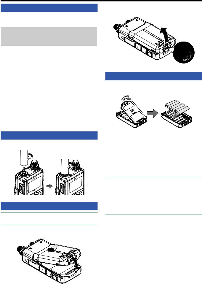
INSTALLING THE BATTERY PACK
Note:
Because the battery pack is provided uncharged, you must charge the battery pack before using it with the transceiver.
Match the guides of the battery pack with the corresponding grooves on the upper rear of the transceiver, then firmly press the battery case to lock it in place.
To remove the battery pack, lift the release lever to unlock the battery pack. Lift the battery pack away from the transceiver.
INSTALLING ALKALINE BATTERIES
1To open the optional KBP-9 battery case lid, press the release lever on the top of the battery case, then pull the cover up.
C A
B
2Insert (or remove) six AAA (LR03) Alkaline batteries.
•When removing the Alkaline batteries from the battery case, pull up on the batteries from the positive (+) terminal.
•Be sure to match the battery polarities with those marked in the bottom of the battery case.
3Align the two tabs at the bottom of battery case, then close the cover until the locking tabs on top click.
4To install the battery case onto (or remove it from) the transceiver, follow “INSTALLING THE BATTERY PACK”.
Note:
Do not use Manganese batteries or Rechargeable batteries in place of Alkaline batteries.
Remove all batteries from the case when it is not expected to be in use for several months.
To lift the battery pack safety catch, use a piece of hardened plastic or metal, such as a screwdriver, that is no more than
6 mm wide and 1 mm thick. It is imperative that you place the implement under only the lip of the safety catch so that you do not damage the release latch.
3-1
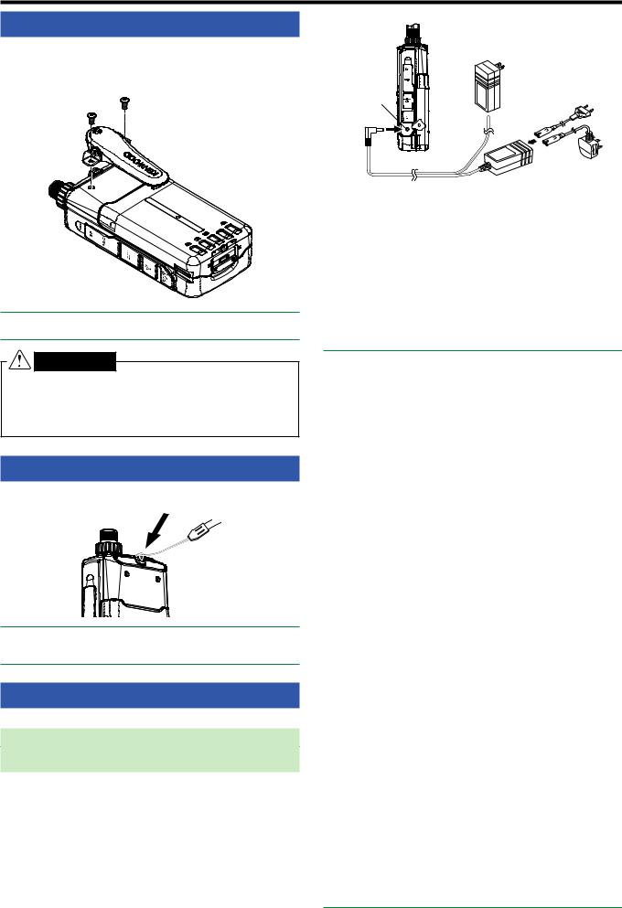
INSTALLING THE BELT CLIP
If desired, you can install the supplied belt clip to the transceiver.
Attach the belt clip firmly using the two supplied M3 x 6 mm binding screws.
Note
Be careful not to pinch your fingers into the belt clip.
CAUTION |
• Do not use glue which is designed to prevent screw |
loosening when installing the belt clip, as it may cause |
damage to the transceiver. Acrylic ester, which is |
contained in these glues, may crack the transceiver’s |
back panel. |
INSTALLING THE HAND STRAP
If desired, you can install the commercially available strap with sufficient strength using the holes of the transceiver.
Note
If the strap is thick and does not pass through the holes, install the strap using the holes of the supplied belt clip.
CHARGING THE BATTERY PACK
For charging the battery pack with the supplied battery charger
The battery pack can be charged after it has been installed onto the transceiver. (The battery pack is provided uncharged for safety purposes.)
1Confirm that the transceiver power is OFF.
•While charging the battery pack, leave the transceiver power OFF.
2Insert the charger plug into the DC IN jack of the transceiver.
DC IN jack
 TH-D74A
TH-D74E
3Plug the charger into an AC wall outlet.
•Charging starts and “Charging” appears on the display.
•“Charging” disappears when charging is completed.
•The backlight is ON when pressing any key while charging.
•“Charging” does not appear when charging with the optional rapid battery charger.
4It takes approximately 3.5 hours to charge an empty KNB-75L Li-ion battery pack. After 3.5 hours, remove the charger plug from the transceiver DC IN jack.
5Unplug the charger from the AC wall outlet.
Note:
Never leave the battery pack in direct sunlight.
The transceiver becomes warm while charging the battery pack.
While the battery pack is charged, the ambient temperature must be within 0°C ~ 40°C (32°F ~ 104°F). Otherwise, charging does not start. If the transceiver senses that the temperature is more than 60°C (140° F) during charging, the transceiver stops charging.
Before recharging the battery pack, use the battery pack until the transceiver stops receiving.
Do not plug the charger into the DC IN jack for more than 24 hours.
Do not expose the charger to dripping or splashing conditions.
No objects filled with liquids, such as vases, shall be placed on the AC adapter or charger.
Do not place the charger into the liquids.
Unplug the charger as soon as possible after the charging period is over.
The charger plug for an AC wall outlet should be used to disconnect an AC adapter from an AC outlet, and the charger plug must remain readily operable.
After the battery pack is charged, do not unplug and plug the charger into the AC outlet again. Unplugging the charger will reset the charging timer and the battery pack will be charged again. This could result in over-charging.
When the battery is installed on the transceiver and you are using an optional rapid battery charger, do not charge the battery from the DC IN jack. Charging the battery from the DC IN jack may result in overcharging the battery which can result in the shortening of the battery life cycle.
If the battery pack is not used for a long time, the battery pack capacity temporarily decreases. In this case, charge the battery and use the battery pack until the transceiver stops receiving. Repeat this procedure several times. The battery pack should recover its capacity.
If the charger is plugged into the DC IN jack before the battery pack is attached, turn the transceiver power ON and then OFF again to initiate charging.
Exceeding the specified charge period shortens the useful life of the KNB-75L battery pack.
The provided charger is designed to charge only the KNB-75L battery pack. Charging other models of battery packs may damage the charger and battery pack.
Do not transmit while charging.
When not in use, store the battery pack in a cool and dry place.
Before charging the battery pack, ensure that the release lever is firmly closed.
Attention should be drawn to the environmental aspects of battery disposal.
It takes approximately 3 hours to charge the KNB-75L with the optional rapid battery charger.
3-2
For charging the battery pack with the optional rapid battery charger
Note:
Insert the battery pack only in the rapid battery charger to charge a battery pack that has been in storage for a long time.
If the battery pack is completely depleted while using the transceiver, remove the battery pack from the transceiver and insert the battery pack in the rapid battery charger.
Charger Error
•While charging, if a problem is detected in the battery, “Charge Error !!” appears on the display.
•The following conditions create charging errors:
•A short in the battery is detected.
•Overvoltage in the battery is detected.
•When a charge error occurs, no key other than [  ] will function.
BATTERY LIFE
Before you operate the transceiver outside using a battery pack, it is important to know how long the battery pack will last. The operating times listed in the table below are measured under the following cyclic conditions:
TX: 6 seconds, RX: 6 seconds, Stand-by: 48 seconds
We recommend you carry extra battery packs with you, in case the battery pack becomes depleted.
Battery Type |
Output Power |
Operating Time/ |
|
Hours (Approx.) |
|||
|
|
||
|
|
|
|
|
H |
6 |
|
KNB-75L |
M |
8 |
|
Li-ion battery pack |
L |
12 |
|
|
EL |
15 |
|
|
H |
4 |
|
KNB-74L |
M |
5 |
|
Li-ion battery pack |
L |
7 |
|
|
EL |
9 |
|
|
H |
- |
|
KBP-9 |
M |
- |
|
Battery case |
L |
3.5 |
|
|
EL |
- |
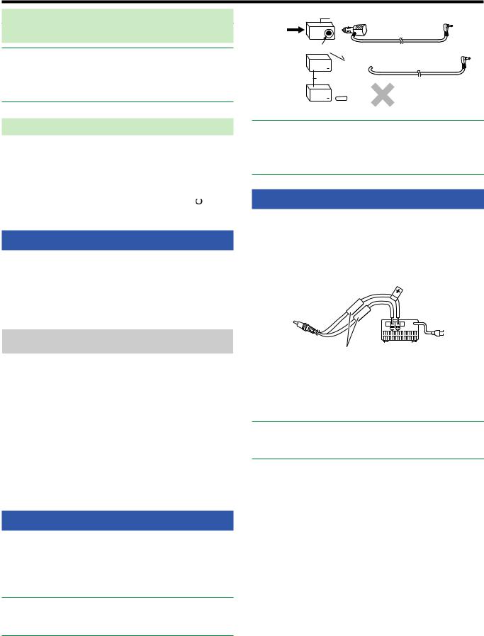
CONNECTING TO A CIGARETTE LIGHTER SOCKET
To connect the transceiver to the cigarette lighter socket in your vehicle, use an optional PG-3J Cigarette Lighter cable.
When the PG-3J is connected to the cigarette lighter plug, the transceiver automatically starts charging the battery pack. While you operate the transceiver, it charges the battery pack in the background.
Note:
To connect with an external 24 V power source via a DC-DC converter, only use the optional PG-3J Cigarette Lighter cable.
Using the PG-2W DC cable in this situation may cause a fire.
|
|
DC-DC Converter |
24V |
12V |
PG-3J |
|
|
Socket
24V  12V
12V

 PG-3J
PG-3J
DC-DC Converter
24V  12V
12V 


 PG-2W
PG-2W
Note:
Do not use the PG-2W to connect directly to a vehicle battery (12 V). Extensive voltage could result in damaging the transceiver.
If the input voltage exceeds approximately 17.5 V, the transceiver automatically turns OFF.
CONNECTING TO A REGULATED POWER SUPPLY
To connect the transceiver to an appropriate regulated DC power supply, use an optional PG-2W DC cable.
1Confirm that the power of both the transceiver and the DC power supply is OFF.
2Connect the optional PG-2W DC cable to the DC power supply; the red lead to the positive (+) terminal, and the black lead to the negative (–) terminal.
Fuses (3 A)
3Connect the barrel plug on the DC cable to the DC IN jack of the transceiver.
•While a DC power supply is connected with the DC IN jack, the transceiver automatically initiates charging the battery pack.
Note:
The supply voltage must be between 12.0 V and 16.0 V to prevent damaging the transceiver. If the input voltage exceeds approximately 17.5 V, the transceiver automatically turns OFF.
3-3
 4 GETTING ACQUAINTED
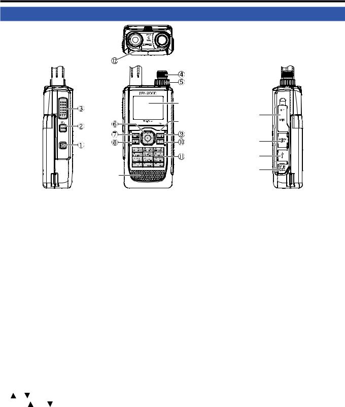
KEY AND CONTROL KNOB OPERATIONS
|
LCD Display |
|
SP/MIC Jacks |
|
Microphone |
|
microSD memory |
|
card slot |
|
Micro-USB Connector |
|
(USB2.0, Type B) |
Speaker |
DC IN (External power supply) |
Jack |
 [
[ ]
]
Press [ ] (1s) to turn the transceiver power ON and OFF.
Press [ ] to turn the backlight ON and OFF when the transceiver power is ON.
The backlight turns OFF when the backlight timer elapses.
When the voice guidance function is not set to OFF, the voice announces the operating states of the transceiver.
When pressing [ ] while announcing, the voice stops.
 [MONI]
Press and hold [MONI] to unmute the speaker in order to monitor signals.
Release [MONI] to return to normal operation.
Press [F], [MONI] to enter the Squelch level adjustment mode.
 [PTT]
[PTT]
Press and hold [PTT], then speak into the microphone to transmit.
 ENC Control
Rotate the ENC control to select an operating frequency, Memory channel, Menu item, setting value and change the scan direction, etc.
 VOL Control
Rotate the VOL control to adjust the speaker volume.
 Multi-Scroll Key
[ ], [ |
] |
Press [ |
] or [ ] to select an operating frequency, |
Memory channel, Menu item, setting value or to change the scan direction, etc.
Press and hold [ ] or [
 ] to change an operating frequency, Memory channel, Menu item, setting value, etc. continuously.
[ ]
]
Press and hold [ ] to select a frequency band in VFO mode.
Press [ ] to move to the next step in various setting modes.
[ ]
]
Press and hold [ ] to select a frequency band in VFO mode.
Press [ ] to move back to the previous step in various setting modes.
[ENT]
Press [ENT] to enter frequency direct entry mode in VFO mode.
Press [ENT] to complete the setting value and move to the next step in Menu mode or various setting modes.
 [MODE]
Press [MODE] to select the mode.
Press [F], [MODE] in DV mode or DR mode to enter
Digital Function menu mode.
This key operates the function displayed in the lower left side.
 [MENU]
Press [MENU] to enter Menu mode.
Press [F], [MENU] to cycle the transmit output power.
 [A/B]
[A/B]
Press [A/B] to select operation band A or B.
Press [F], [A/B] to switch the Single band mode and Dual band mode.
This key operates the function displayed in the lower right side.
 [F]
[F]
Press [F] to enter Function select mode.
Press [F] (1s) to turn the transceiver Key lock function ON and OFF.
 12 Keypad [VFO] (1)
Press [VFO] to enter VFO mode. In Memory channel or CALL channel, press [F], [VFO] to copy the current Memory channel or Call channel to the VFO (memory shift).
4-1

[MR] (2)
Press [MR] to enter Memory Channel mode.
Press [F], [MR] to move to the Memory channel store screen.
[CALL] (3)
Press [CALL] to select the Call channel.
Press [F], [CALL] to store the current operating frequency to the Call channel.
[MSG] (4)
Press [MSG] to display the APRS Message list.
Press [F], [MSG] to enter the New Message input mode.
[LIST] (5)
Press [LIST] to display the APRS Station list.
•Each time you press [F], [LIST], the mode cycles through the following: APRS mode ON KISS mode ON OFF.
[BCN] (6)
Press [BCN] to transmit the beacon when APRS mode is
ON.
Press [F], [BCN] to transmit the Object.
[REV] (7)
Press [REV] to turn the Reverse function ON or OFF.
Press [F], [REV] to select the Shift direction.
[TONE] (8)
Press [TONE] to turn the Tone function ON.
•Each time you press [TONE], the function cycles through the following: Tone ON CTCSS ON DCS ON Cross Tone ON OFF.
Press [F], [TONE] to enter the Tone frequency, CTCSS frequency, DCS code, or Cross Tone setup mode.
Press [F], [TONE] (1s) to start the Tone frequency,
CTCSS frequency, or DCS code scan.
[PF1] (9)
Press [PF1] to activate its programmed function.
Press [F], [PF1] to turn the Attenuator function ON or OFF.
[MARK] (0)
Press [MARK] to display the Position memory list.
Press [MARK] (1s) to enter the Mark Way point registration mode.
Press [F], [MARK] display your “My position”.
[MHz] ( )
)
Press [MHz] to enter the MHz mode. Press [MHz] (1s) to start the MHz scan.
Press [F], [MHz] to enter Fine tuning function mode.
[PF2] (#)
Press [PF2] to activate its programmed function.
Press [F], [PF2] to enter Frequency step setup mode or Fine step frequency setup mode.
 ON AIR/ Busy Indicator
The indicator lights red in transmitting, and lights green in receiving.
4-2
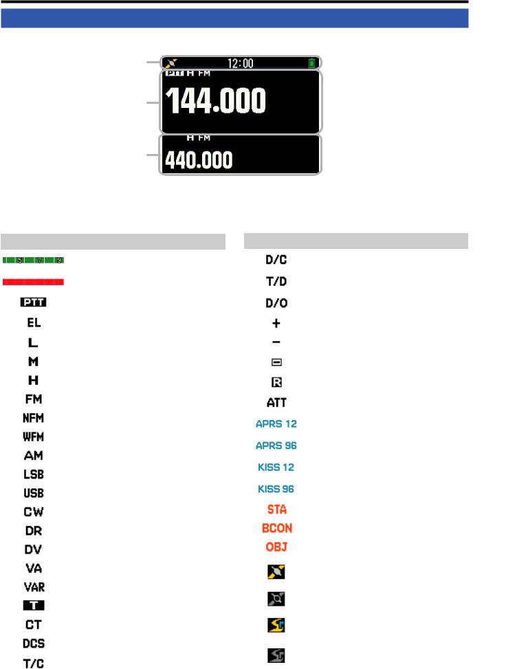
DISPLAY
Frequency Display
Common icon Display Area
A Band Display Area
B Band Display Area
Various function indicator
Indicator |
Description |
|
|
|
Performs as the S meter when receiving a |
|
signal. |
|
|
|
Displays the selected power level while |
|
transmitting. |
|
|
|
Indicates the transmission band. |
|
|
|
Appears while using Economic low output |
|
power. |
|
|
|
Appears while using Low output power. |
|
|
|
Appears while using Medium output power. |
|
|
|
Appears while using High output power. |
|
|
|
Appears while in FM mode. |
|
|
|
Appears while in Narrow FM mode. |
|
|
|
Appears while in Wide FM mode. |
|
|
|
Appears while in AM mode. |
|
|
|
Appears while in LSB mode. |
|
|
|
Appears while in USB mode. |
|
|
|
Appears while in CW mode. |
|
|
|
Appears while in Digital Repeater mode. |
|
|
|
Appears while in Digital Voice mode. |
|
|
|
Appears when Voice Alert is set to “ON”. |
|
|
|
Appears when Voice Alert is set to “RX Only”. |
|
|
|
Appears when the Tone function is ON. |
|
|
|
Appears when the CTCSS function is ON. |
|
|
|
Appears when the DCS function is ON. |
|
|
|
Appears when the Cross tone function is |
|
“TONE/CTCSS”. |
|
|
Indicator |
Description |
|
|
|
Appears when the Cross tone function is “DCS/ |
|
CTCSS”. |
|
|
|
Appears when the Cross tone function is |
|
“TONE/DCS”. |
|
|
|
Appears when the Cross tone function is “DCS/ |
|
OFF”. |
|
|
|
Appears when the Shift function is set to plus. |
|
|
|
Appears when the Shift function is set to minus. |
|
|
|
Appears when the Shift function is set to -7.6 |
|
MHz. (TH-D74E only) |
|
|
|
Appears when the Reverse function is ON. |
|
|
|
Appears when the Attenuator function is ON. |
|
|
|
Appears when the packet communication |
|
speed in APRS mode is set to 1200 bps. |
|
|
|
Appears when the packet communication |
|
speed in APRS mode is set to 9600 bps. |
|
|
|
Appears when the packet communication |
|
speed in KISS mode is set to 1200 bps. |
|
|
|
Appears when the packet communication |
|
speed in KISS mode is set to 9600 bps. |
|
|
|
Appears while in Stand-by (Packet mode). |
|
|
|
Appears when the Beacon function is ON. |
|
|
|
Appears when the Object function is ON. |
|
|
|
Appears when the built-in GPS function is ON. |
|
Blinks when the built-in GPS function is |
|
positioning. |
|
|
|
Appears when the built-in GPS function is in |
|
Save mode. |
|
|
|
Appears when the GPS Track Log function is |
|
ON. Blinks when the built-in GPS function is |
|
positioning. |
|
|
|
Appears when the GPS Track Log function is |
|
ON and the built-in GPS function is in Save |
|
mode. |
|
|
4-3

Menu Mode Display |
D-STAR (DV/DR mode) Display |
KEY GUIDE Display Area
Indicator |
Description |
Appears when a message is received.
Appears when recording communication.
Appears when recording a voice message is paused.
Appears when the Priority Scan function is ON.
Appears when FM radio mode is ON.
The Bluetooth® function is ON.
Connected to a Bluetooth® device.
Appears when a microSD memory card is recognized. Blinks when a microSD memory card is mounting or unmounting.
Appears when Weather Alert is ON.
Blinks when Weather Alert is detected.
(TH-D74A only.)
Appears when the key lock is ON.
Indicates the battery level.
Appears during charging of the battery.
Indicates the memory group number.
Indicates the Weather Channel. (TH-D74A only.)
Appears when the Memory Channel Lockout function is ON.
Appears when the Repeater Lockout function is ON.
Indicator |
Description |
Appears when Code squelch is ON.
TX: Appears in interrupt communication.
RX: Blinks while receiving interrupt communication.
Appears when the auto reply function is ON.
Appears in GPS transmission.
Appears while in data communication mode.
Blinks while receiving fast data.
Appears when a packet loss happens.
Indicates a repeater for local area call.
Indicates a repeater for call within zone.
Indicates a repeater for gateway call.
Appears when Callsign squelch is ON.
4-4
 5 BASIC OPERATIONS
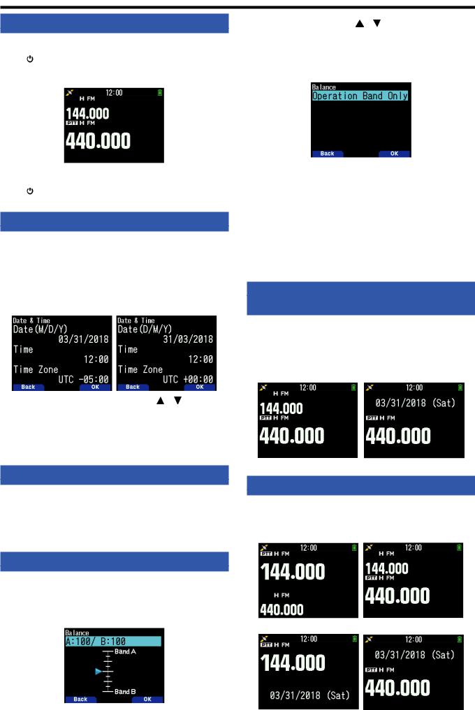
SWITCHING THE POWER ON/ OFF
Switching the Power ON
] (1s).
The power on message momentarily appears, and frequency screen appears.
Switching the Power OFF
] (1s).
ADJUSTING THE INTERNAL CLOCK
When the built-in GPS function is turned ON, the year, month, day, and time are automatically set from the GPS satellite information. The default setting of the built-in GPS function
is [On]. If the GPS information cannot be received, you can manually enter the date and time.
1Access Menu No. 950.
Date & Time screen appears by pressing [MENU], [PF1],
[LIST], [MARK].
2 Set the date, time, and time zone |
] or [ENC] |
control. |
|
3Press [A/B].
The date, time, and time zone are set.
4Press [MENU] to return to the frequency screen.
2 Change the balance |
] or [ENC] control. |
•Band A and B are set to the same volume level (MAX) as a default setting. Pressing [MODE] returns to the previous screen without changing the setting.
When you select [Operation Band Only], the sound of the operation band is outputted with priority.
Setting examples
When used in combination with APRS:
When using band A for voice calls, use the transceiver with the sound of band B set to a low volume level or muted.
When simultaneously scanning two waves:
If [Operation Band Only] is set, a voice is output only for the operation band when the operation and non-operation band become busy at the same time.
3Press [ENT] to set the volume balance.
4Press [MENU] to return to the frequency screen.
SELECTING DUAL BAND MODE/ SINGLE BAND MODE
You can switch the transceiver between dual band operation and single band operation.
1 Press [F], [A/B].
•Each time you press [F], [A/B], the transceiver switches between Single band and Dual band mode.
Dual Band mode |
Single Band mode |
ADJUSTING THE VOLUME
Rotate the VOL control to increase the volume and counterclockwise to decrease the volume.
When no sound is heard (the squelch is closed), you can adjust the noise level by rotating the VOL control while pressing the [MONI].
VOLUME BALANCE (BAND A/B)
This function adjusts the volume balance when using the transceiver with dual bands.
1Access Menu No. 910.
Volume balance screen appears by pressing [MENU],
[PF1], [VFO], [MARK].
SELECTING AN OPERATION BAND
You can select a band A or B as an operation band for changing the frequency or setting various operations, etc.
1 Press [A/B] to select operating band A or B.
Dual Band A
Single Band A
5-1

SELECTING A FREQUENCY BAND
You can |
frequency bands for bands A and B. |
|
1 |
] (1s). |
|
• |
Each time you |
] (1s), you cycle to the next |
|
frequency band. |
|
Band A : 144 220 430 144 (MHz).
Band B : 430 UHF(470-524) LF/MF(AMBC)
HF 50 FMBC 118 144 VHF(174-216) 200/300 430 (MHz).
Note:
220 MHz band in Band A is used by the TH-D74A only.
Frequency ranges:
•118 MHz: Band B 108 ~ 136 MHz
•144 MHz: 136 ~ 174 MHz
•VHF: 174 ~ 216 MHz (TH-D74A) 174 ~ 230 MHz (TH-D74E)
•220 MHz: 216 ~ 260 MHz (TH-D74A only)
•200/300 MHz: Band B 216 ~ 410 MHz (TH-D74A)
230 ~ 410 MHz (TH-D74E)
•430 MHz: 410 ~ 470 MHz
•UHF: 470 ~ 524 MHz
•LF/MF(AMBC): 0.1 ~ 1.71 MHz
•HF: 1.71 ~ 29.7 MHz
•50: 29.7 ~ 76 MHz
•FMBC: 76 ~ 108 MHz
SELECTING THE DEMODULATION MODE
You can select the demodulation mode.
1Press [A/B] to select an operation band.
2Press [MODE] to select a demodulation mode.
• Each press changes the demodulation mode as follows.
Band A: FM/NFM DR (DV) (Returns to FM/NFM)
Band B: FM/NFM DR (DV) AM LSB USB CW(Returns to FM/NFM)
Note:
Switching between the DV and DR modes is not possible with the [MODE] button. (Refer to “Digital Function Menu”.)
The DV and DR mode cannot be selected for both band A and
B at the same time.
Switching between the FM and NFM modes is not possible with the [MODE] button.
SELECTING A FREQUENCY
There are 3 operating modes available to choose from: VFO mode, Memory Channel mode, and Call Channel mode.
VFO Mode
VFO mode allows you to manually change the operating frequency.
1Press [VFO] to enter VFO mode.
2Rotate the ENC control to select your desired operating frequency.
• You can also select a frequency by using |
] |
keys. |
|
•The default step frequency for the [ENC] control varies according to the model and operating frequency band:
Model |
144 MHz |
220 MHz |
430 MHz |
|
|
|
|
TH-D74A |
5 kHz |
20 kHz |
25 kHz |
|
|
|
|
TH-D74E |
12.5 kHz |
- |
25 kHz |
|
|
|
|
Note:
220 MHz band is used by the TH-D74A only.
MHz Step
To adjust the frequency by a larger amount, press [MHz] to enter MHz mode, then rotate the ENC control or use the
[ ]/[ ] keys to adjust the frequency in steps of 1 MHz. Press [MHz] again to exit MHz mode and adjust the frequency using the normal step frequency.
Frequency Direct Entry
If the desired operating frequency is far from the current frequency, using the keypad is the quickest way to change the frequency.
1Press [ENT].
The Direct Frequency Entry display appears.
2Press the numeric keys ([0] ~ [9]) to enter your desired frequency.
3To set the entered frequency, press 6 digit.
•Pressing [ENT] before entering all of the digits will set the remaining digits to 0.
Memory Channel Mode
Memory Channel mode allows you to quickly select a frequently used frequency and related data which you have stored in the memory channel.
1Press [MR] to enter Memory Channel mode.
The Memory channel number appears on the display.
2Rotate the [ENC] control to select your desired Memory channel.
Call Channel Mode
Call Channel mode allows you to quickly select a preset channel to allow immediate calls on that frequency. The Call channel can be conveniently used as an emergency channel within your group.
1Press [CALL] to enter Call Channel mode. “C” appears on the display.
2Press [CALL] again, and the transceiver will return to the previous frequency.
• The default settings are as follows.
TH-D74A
|
Band (Mode) |
Call Channel |
Memory Name |
||
|
|
|
|
||
VHF (except DV/DR mode) |
146.520 |
MHz (FM) |
Call VHF (FM) |
||
|
|
|
|
||
VHF(DV/DR mode) |
144.000 |
MHz (DV) |
Call VHF (DV) |
||
|
|
|
|
|
|
220 |
MHz(except DV/DR mode) |
223.500 |
MHz (FM) |
Call 220M |
(FM) |
|
|
|
|
|
|
220 |
MHz(DV/DR mode) |
223.000 |
MHz (DV) |
Call 220M |
(DV) |
|
|
|
|
||
UHF(except DV/DR mode) |
446.000 |
MHz (FM) |
Call UHF (FM) |
||
|
|
|
|
||
UHF(DV/DR mode) |
440.000 |
MHz (DV) |
Call UHF (DV) |
||
|
|
|
|
|
|
5-2
TH-D74E
Band |
Call Channel |
Memory Name |
|
|
|
VHF (except DV/DR mode) |
145.500 MHz (FM) |
Call VHF (FM) |
|
|
|
VHF(DV/DR mode) |
144.8125MHz (DV) |
Call VHF (DV) |
|
|
|
UHF(except DV/DR mode) |
433.500 MHz (FM) |
Call UHF (FM) |
|
|
|
UHF(DV/DR mode) |
433.6125MHz (DV) |
Call UHF (DV) |
|
|
|
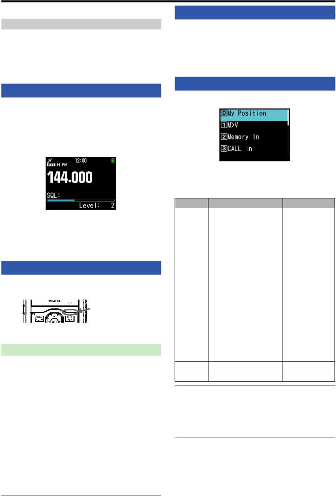
MONITOR
When you are receiving while the squelch function is ON, weak signals may become intermittent.
1Press and hold [MONI].
•The speaker is unmuted and you can monitor the signals.
2Release [MONI] to return to normal operation.
ADJUSTING THE SQUELCH
Squelch is used to mute the speaker when no signals are present. With the squelch level set correctly, you will hear sound only while actually receiving a signal. The higher the squelch level selected, the stronger the signals must be in order to hear them.You can set the squelch level separately for Bands A and B.
1Press [F], [MONI].
The squelch level appears on the display.
2Press [ ]/[
]/[ ] or rotate the ENC control of your selected band, when no signals are present, and select the squelch level at which the background noise is just eliminated.
3Press [ENT].
The squelch level is set.
TRANSMITTING
1Select your desired band and frequency/channel.
2Press and hold [PTT], and speak into the microphone to transmit.
Microphone
3 When you finish speaking, release the [PTT].
Selecting an Output Power
Selecting a lower transmit power is the best way to reduce battery consumption, if communication is still reliable.
Press [F], [MENU] to select high (H), medium (M), low (L), or economic low (EL) power.
Battery Pack |
H |
Approx. 5 W |
|
KNB-75L |
|||
|
|
||
KNB-74L |
|
|
|
M |
Approx. 2 W |
||
Battery Case |
|||
|
|
||
KBP-9 |
|
|
|
|
|
||
(AAA Alkaline |
L |
Approx. 0.5 W |
|
batteries) |
|||
|
|
||
External Power |
|
|
|
EL |
Approx. 0.05 W |
||
Supply |
|||
|
|
||
|
|
|
|
|
|
|
Note:
You can program different power settings for bands A and B.You can not change the output power in transmitting.
You can not set the output power in each frequency band.
FUNCTION SELECT MODE
Press [F] to enter Function Select mode. Press [F] again to return to the previous screen.
Pressing each key in the function select mode performs the operation of the second function assigned to each key.
The function of each key may differ depending on the mode when [F] is pressed (refer to the following table).
Key |
Second function |
Remarks |
|
|
|
|
|
[MARK] (0) |
My position |
Built-in GPS is On. |
|
|
|
|
|
[VFO] (1) |
Memory shift |
Only in Memory |
|
mode or Call mode |
|||
|
|
||
|
|
|
|
[MR] (2) |
Memory channel registration |
|
|
|
|
|
|
[CALL] (3) |
Call channel registration |
|
|
|
|
|
|
[MSG] (4) |
APRS message creation |
|
|
|
|
|
|
[LIST] (5) |
APRS/ KISS mode switching |
|
|
|
|
|
|
[BCN] (6) |
Object beacon |
Only in APRS mode |
|
|
|
|
|
[REV] (7) |
Shift |
|
|
|
|
|
|
[TONE] (8) |
Tone frequency |
|
|
|
|
|
|
[PF1] (9) |
Attenuator |
|
|
|
|
|
|
[MHz] (*) |
Fine mode |
|
|
|
|
|
|
[PF2] (#) |
Frequency Step |
|
|
|
|
|
|
[MODE] |
Digital function menu |
Only in DV/DR |
|
mode |
|||
|
|
||
|
|
|
|
[MENU] |
Transmission power |
|
|
|
|
|
|
[A/B] |
Dual or Single band switching |
|
[F]Function select mode end
[MONI] Squelch setting
Note:
The tone frequency changes to the following setting items depending on the conditions of this transceiver.
Tone OFF: Invalid
Tone ON: Tone frequency CTCSS ON: CTCSS frequency DCS ON: DCS frequency
Cross Tone ON: Cross tone combination
5-3
 6 MENU MODE
Many functions on this transceiver are selected or configured through the Menu instead of physical controls.
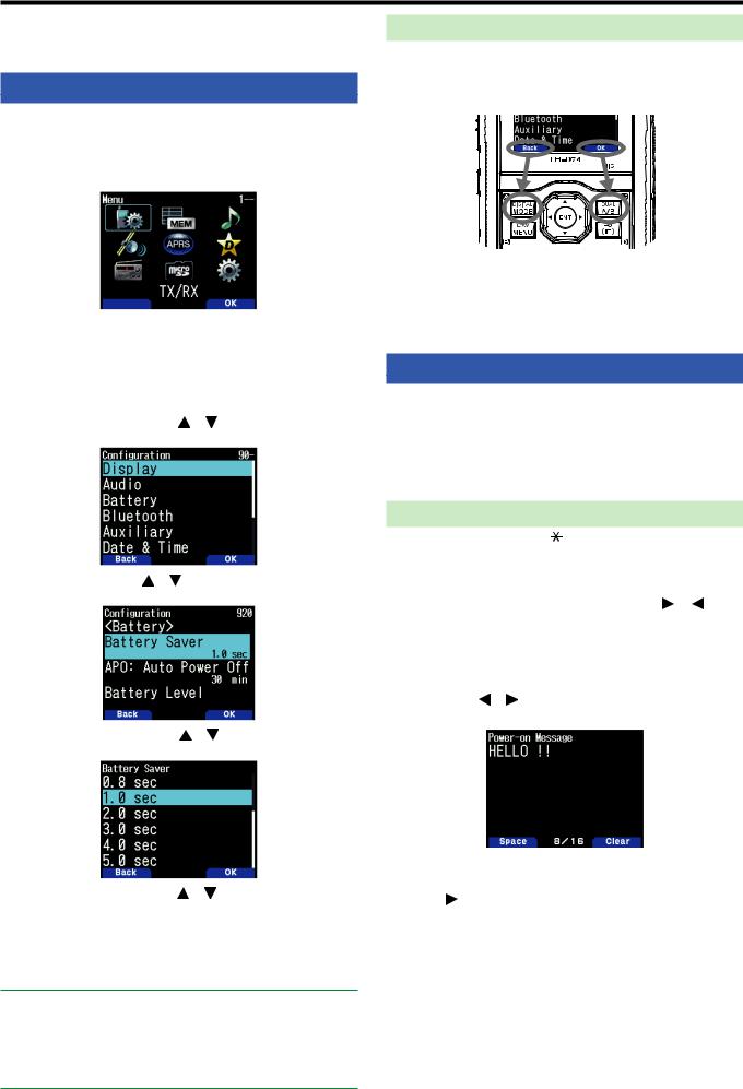
MENU ACCESS
Example: Setting the time for [Battery Saver] of Menu No. 920.
1Press [MENU].
The transceiver enters the Menu mode. The icon currently selected by the cursor is highlighted, and the item name is displayed at the bottom of the screen. (Example: TX/RX)
Directly Entering a Menu Number (Direct Access)
You can also directly enter a menu number using the number keys from this screen.
Press [PF1], [MR], [MARK] for Menu No.920. In this case, you can move to step 4.
2 Select [Configuration] with [ ]/[ ] or [ENC] control and press [A/B].
3 Select [Battery] with [ ]/[ ] or [ENC] control and press
[A/B].
4 Select [Battery Saver] with [ ]/[ ] or [ENC] control and press [A/B].
Software Key operation
Software keys ([Back], [OK], etc.) are displayed in the key guide area of various setting screens and other screens. To select or operate the displayed functions, press the corresponding 

Example:
[Back] Press [MODE]: Returns to the previous screen without confirming the displayed setting.
[OK] Press [A/B]: Changes to the next screen.
CHARACTER ENTRY
In the screens that require you to enter text such as the screen for entering a memory name or power-on message, there are two methods to enter text. One is to enter text using the number keys in the same ways as a mobile phone and the other is to enter text by selecting characters one by one with the Multi-Scroll Key or [ENC] control.
Keypad Character Entry
1 Enter text with [0] to [9], [ ], [#], and [ENT].
•The each press of a key changes the character that can be entered.
• To enter another character assigned to |
key, |
move the cursor to the next position |
] |
moves the cursor to the previous position) and enter the next character.
•Pressing [A/B] deletes a character. The character at the cursor position is deleted. The backspace operation is
performed |
is a blank space. |
• Pressing |
] moves the cursor. |
Example: Entering the power-on message (Menu No.903)
5 Select a setting value with [ ]/[ ] or [ENC] control and press [A/B] to set the value.
6Press [MENU].
The menu mode ends and the frequency screen appears. For subsequent menu operations, steps 1 to 4 will be referred to as “Access Menu No. XXX”.
Note:
Pressing [PTT] during each operation ends menu mode without confirming the setting.
Pressing [MODE] during each operation returns to the previous screen. Also, pressing [MODE] during step 4 discards the new setting value and returns to the previous operation.
Pressing [MENU] in scanning cancels scan.
•Pressing [MODE] input the space.
•Pressing [A/B] clears the text.
2 ].
The cursor moves to the right.
3Press [ENT].
The text is confirmed and text input ends.
6-1

Entering Text with the |
Key or [ENC] |
|
1 |
character |
] or [ENC] control. |
2 |
]. |
|
The character or symbol is entered and the cursor moves to the right.
Pressing [A/B] deletes the character selected by the cursor. If it is pressed when there is no character selected by the cursor, the cursor moves to the left.
Auto Cursor Shift
This function provides assistance for entering text using the number keys. It is convenient to use this function when
consecutively entering characters with the same key because it automatically moves the cursor to the right after a set time has passed.
You can set this time until the cursor is moved to the desired time.
1Access Menu No. 945.
Select [Off], [1.0], [1.5], or [2.0] seconds.
2Press [ENT].
MENU CONFIGURATION
No. |
Display |
Description |
Setting Values |
TX/RX - RX |
|
|
|
100 |
Programmable VFO |
Programmable VFO setting (Band A only) |
Varies with the selected frequency band |
101 |
Beat Shift |
Beat shift |
Type 1 - Type 8 |
102 |
Detect Out Select |
Detect output select |
Off (AF)/ IF/ Detect |
103 |
FM Narrow |
FM narrow |
Off/ On |
104 |
MW/ SW Antenna |
MW/ SW Antenna |
ANT connector / Bar Antenna |
105 |
WX Alert |
Weather alert |
Off/ On (TH-D74A only) |
TX/RX - TX |
|
|
|
110 |
TX Inhibit |
TX inhibit |
Off/ On |
|
|
|
|
111 |
Time-out Timer |
Time-out timer |
0.5/ 1.0/ 1.5/ 2.0/ 2.5/ 3.0/ 3.5/ 4.0/ 4.5/ 5.0/ 10.0 [min] |
112 |
Mic. Sensitivity |
Microphone sensitivity |
High/ Medium/ Low |
TX/RX - RX Filter |
|
|
|
120 |
SSB High Cut |
SSB high cut frequency |
2.2/ 2.4/ 2.6/ 2.8/ 3.0 [kHz] |
121 |
CW Width |
CW bandwidth |
0.3/ 0.5/ 1.0/ 1.5/ 2.0 [kHz] |
122 |
AM High Cut |
AM high cut frequency |
3.0/ 4.5/ 6.0/ 7.5 [kHz] |
|
|
|
|
TX/RX - Scan |
|
|
|
130 |
Resume |
Resume method |
Time/ Carrier/ Seek |
131 |
Resume (Digital) |
Resume method (Digital) |
Time/ Carrier/ Seek |
132 |
Time Restart |
Time operate restart time |
1 - 5 - 10 [sec] |
|
|
|
|
133 |
Carrier Restart |
Carrier operate restart time |
1 - 2 - 10 [sec] |
134 |
Priority Scan |
Priority scan |
Off/ On |
135 |
Scan Auto Backlight |
Scan auto backlight |
Off/ On |
136 |
Auto Weather Scan |
Auto Weather Channel Scan |
Off/ On (TH-D74A only) |
TX/RX - Repeater |
|
|
|
140 |
Offset Frequency |
Offset frequency |
Varies with the selected frequency band |
141 |
Auto Offset |
Auto repeater offset |
Off/ On |
|
|
|
|
142 |
CALL Key |
CALL key function |
CALL (TH-D74A)/ 1750Hz (TH-D74E) |
143 |
1750Hz TX Hold |
1750 Hz TX hold |
Off/ On |
TX/RX - VOX |
|
|
|
150 |
VOX |
VOX on/ off |
Off/ On |
151 |
Gain |
VOX gain level |
0 - 4 - 9 |
152 |
Delay |
VOX delay time |
250/ 500/ 750/ 1000/ 1500/ 2000/ 3000 [ms] |
|
|
|
|
153 |
TX on Busy |
VOX on busy |
Off/ On |
TX/RX - DTMF |
|
|
|
160 |
Encode Speed |
Encode speed |
50/ 100/ 150 [ms] |
|
|
|
|
161 |
Pause Time |
Pause time |
100/ 250/ 500/ 750/ 1000/ 1500/ 2000 [ms] |
|
|
|
|
162 |
TX Hold |
TX hold |
Off/ On |
|
DTMF Memory |
|
Up to 10 channels for DTMF memory channel |
163 |
DTMF memory |
Up to 16 characters for DTMF memory name |
|
|
|
|
Up to 16 digits for DTMF memory code |
|
EchoLink Memory |
|
Up to 10 channels for EchoLink memory channel |
164 |
EchoLink memory |
Up to 8 characters for EchoLink memory name |
|
|
|
|
Up to 8 digits for one channel code |
TX/RX - CW |
|
|
|
170 |
Pitch Frequency |
Pitch frequency |
400 - 800 - 1000 [Hz] |
171 |
Reverse |
Reverse |
Normal/ Reverse |
6-2

No. |
Display |
Description |
Setting Values |
|
TX/RX - Others |
|
|
||
|
|
|
|
|
180 |
QSO Log |
QSO log |
Off/ On |
|
181 |
LED Control |
LED control |
RX: Check |
|
FM Radio: Uncheck |
||||
|
|
|
||
Memory - Memory Channel |
|
|
||
200 |
View List |
Memory channel list |
- |
|
201 |
Group Name |
Memory group name input |
Up to 16 characters |
|
202 |
Recall Method |
Memory channel recall method |
All Bands/ Current Band |
|
203 |
Group Link |
Memory group link registration |
register up to 30 memory group links |
|
204 |
CALL Ch List |
CALL channel list |
- |
|
Memory - Repeater List |
|
|
||
210 |
View List |
Repeater list |
- |
|
Memory - Callsign List |
|
|
||
220 |
View List |
Callsign list |
- |
|
Audio File - Recording File |
|
|
||
|
|
|
|
|
300 |
View List |
Recording file list |
- |
|
301 |
Recording |
Recording |
Off/ On |
|
302 |
Recording Band |
Recording band |
A Band/ B Band |
|
Audio File - Voice Message |
|
|
||
310 |
View List |
Voice message list |
- |
|
311 |
TX Monitor |
TX monitor |
Off / On |
|
312 |
Digital Auto Reply |
Digital auto reply |
Off/ Voice Message 1 - Voice Message 4 |
|
|
|
|
|
|
GPS - Basic Settings |
|
|
||
400 |
Built-in GPS |
Built-in GPS |
Off/ On |
|
401 |
My Position |
My position |
GPS/ My Position 1 - 5 |
|
402 |
Position Ambiguity |
Position ambiguity mode |
Off/ 1-Digit - 4-Digit |
|
403 |
Operating Mode |
Built-in GPS operating mode |
Normal/ GPS Receiver |
|
404 |
Battery Saver |
Battery saver time |
Off/ 1min/ 2min/ 4min/ 8min/ Auto |
|
405 |
PC Output |
GPS data output to PC |
Off/ On |
|
406 |
Sentence |
Sentence |
$GPGGA/ $GPGLL/ $GPGSA / $GPGSV/ $GPRMC/ |
|
$GPVTG |
||||
|
|
|
||
GPS - Track Log |
|
|
||
410 |
Track Log |
Track log recording |
Off/ On |
|
411 |
Clear Track Log |
Clear track log |
- |
|
412 |
Record Method |
Record method |
Time/ Distance/ Beacon |
|
413 |
Interval |
Interval time |
2 - 10 - 1800 [sec] |
|
414 |
Distance |
Distance |
0.01 - 9.99 [mile/ km/ nm] |
|
APRS - Basic Settings |
|
|
||
500 |
My Callsign |
Callsign entry |
Up to 9 characters |
|
501 |
Icon |
Icon |
Person/ Bicycle/ Motorcycle, etc. (total 68 icons) |
|
|
Position Comment |
|
Off Duty/ Enroute/ In Service/ Returning/ Committed/ |
|
502 |
Position comment |
Special/ PRIORITY/ CUSTOM0 ~ CUSTOM6/ |
||
|
|
|
EMERGENCY! |
|
|
|
|
Status text: 1 - 5 |
|
503 |
Status Text |
Status text |
TX Rate: Off/ 1/1 - 1/4 - 1/8 |
|
|
|
|
Up to 42 characters |
|
|
|
|
Type: New-N/ Relay/ Region/ Others1-Others3, |
|
504 |
Packet Path |
Packet path type |
WIDE1-1: Off/On, RELAY: Off/On, ABBR: Up to 5 |
|
characters, |
||||
|
|
|
||
|
|
|
Total Hops: 0 - 1 - 7, Path: Up to 79 characters |
|
505 |
Data Speed |
Data communications speed |
1200bps/ 9600bps |
|
506 |
Data Band |
Internal data band type |
A Band/ B Band |
|
|
|
|
|
|
507 |
DCD Sense |
DCD sense type |
Busy/ Detect Data/ Off (Ignore) |
|
508 |
TX Delay |
TX delay time |
100/ 150/ 200/ 300/ 400/ 500/ 750/ 1000 [ms] |
|
509 |
APRS Lock |
APRS lock |
Frequency/ PTT/ APRS Key: All unchecked |
|
APRS - Beacon TX Control |
|
|
||
510 |
Method |
Method |
Manual/ PTT/ Auto/ SmartBeaconing |
|
511 |
Initial Interval |
Initial Interval timer |
0.2/ 0.5/ 1/ 2/ 3/ 5/ 10/ 20/ 30/ 60 [min] |
|
512 |
Decay Algorithm |
Decay Algorithm |
Off/ On |
|
513 |
Prop. Pathing |
Prop. Pathing |
Off/ On |
|
514 |
Speed |
Speed |
Off/ On |
|
515 |
Altitude |
Altitude |
Off/ On |
|
6-3

No. |
Display |
Description |
Setting Values |
|
|
|
|
Name: up to 9 characters, Type: Live Object/ Killed |
|
|
Object |
|
Object/ Live Item/ Killed Item, Method: Off/ Temp./ |
|
516 |
Object name |
Auto(15 min)/ Auto(30 min)/ Auto(60 min), N(S): Latitude, |
||
|
|
|
E(W): Longitude, Icon (Total 68 kinds): Eyeball/ Portable |
|
|
|
|
(Tent)/ HAM store, etc., Comment: up to 42 characters |
|
APRS - QSY Information |
|
|
||
|
|
|
|
|
520 |
QSY Info. in Status |
QSY information in status |
Off/ On |
|
521 |
Tone/Narrow |
Tone/ Narrow |
Off/ On |
|
522 |
Shift/Offset |
Shift/ Offset |
Off/ On |
|
523 |
QSY Limit Distance |
QSY limit distance |
Off/ 10/ 20 … 2490/ 2500 [mile/ km/ nm] |
|
APRS - SmartBeaconing |
|
|
||
530 |
Low/High Speed |
Low speed/ High speed setting |
Low Speed: 2 - 5 - 30 [mile/h/ km/h/ knots] |
|
High Speed: 2 - 70 - 90 [mile/h/ km/h/ knots] |
||||
|
|
|
||
531 |
Slow Rate |
Low speed transmission interval time |
1- 30 - 100 [min] |
|
532 |
Fast Rate |
High speed transmission interval time |
10 - 120 - 180 [sec] |
|
533 |
Turn Angle |
Driving direction change, minimum value |
5 deg - 28 deg - 90 deg |
|
setting |
||||
|
|
|
||
534 |
Turn Slope |
Driving direction change, additional value |
1 (10deg/speed) - (26 10deg/speed) - 255 (10deg/speed) |
|
setting |
||||
|
|
|
||
535 |
Turn Time |
Minimum time delay between each |
5 - 60 - 180 [sec] |
|
beacon transmission |
||||
|
|
|
||
APRS - Waypoint |
|
|
||
540 |
Format |
Way point format |
NMEA/ MAGELLAN/ KENWOOD |
|
541 |
Length |
Way point name length |
6-Char/ 7-Char/ 8-Char/ 9-Char |
|
542 |
Output |
Way point output type |
All/ Local/ Filtered |
|
APRS - Packet Filter |
|
|
||
550 |
Position Limit |
Position limit |
Off/ 10/ 20 … 2490/ 2500 [mile/ km/ nm] |
|
|
|
|
|
|
551 |
Filter Type |
Filter type |
Weather/ Digipeater/ Mobile/ Object/ NAVITRA/ 1-WAY/ |
|
Others |
||||
|
|
|
||
APRS - Message |
|
|
||
560 |
User Phrase |
User phrases |
Up to 32 characters x 20 phrases |
|
561 |
Auto Reply |
Auto message reply |
Off/ On |
|
562 |
Reply To |
Reply to |
Up to 9 characters |
|
563 |
Reply Delay Time |
Reply delay time |
0/ 10/ 20/ 30/ 60 [sec] |
|
564 |
Reply Message Text |
Reply message text input |
Up to 50 characters |
|
APRS - Notification |
|
|
||
570 |
RX Beep |
RX beep |
Off/ Message Only/ Mine/ All New/ All |
|
571 |
TX Beep |
TX beep |
Off/ On |
|
572 |
Special Call |
Special call |
Up to 9 characters |
|
573 |
Display Area |
Display area |
Entire Always/ Entire Display/ One Line |
|
574 |
Interrupt Time |
Interrupt time |
3/ 5/ 10/ 20/ 30/ 60/ infinite [sec] |
|
575 |
APRS Voice |
APRS voice |
Off/ On |
|
APRS - Others |
|
|
||
580 |
PC Output |
PC output type |
Off/ Raw Packets/ Waypoints |
|
581 |
Network |
Network type |
APRS[APK004]/ Altnet |
|
582 |
Voice Alert |
Voice alert type |
Off/ On/ RX Only |
|
|
|
|
|
|
583 |
VA Frequency |
VA frequency type |
67.0 - 100.0 - 254.1 Hz |
|
|
|
|
|
|
584 |
Message Group Code |
Message group code |
Up to 9 characters x 6 codes (ALL,QST,CQ,KWD) |
|
585 |
Bulletin Group Code |
Bulletin group code |
Up to 5 characters x 6 codes |
|
Digital - RX History |
|
|
||
|
|
|
|
|
600 |
View History |
View History |
- |
|
Digital - TX/RX |
|
|
||
610 |
My Callsign |
Callsign entry |
Up to 8 characters + up to 4 characters |
|
|
|
|
|
|
611 |
TX Message |
TX message |
Off/ 1/ 2/ 3/ 4/ 5 |
|
612 |
Direct Reply |
Direct reply |
Off/ On |
|
613 |
Auto Reply Timing |
Auto reply timing |
Immediate/ 5/ 10/ 20/ 30/ 60 [sec] |
|
614 |
Data TX End Timing |
Data TX end timing |
Off/ 0.5/ 1/ 1.5/ 2 [sec] |
|
615 |
EMR Volume Level |
EMR Volume level |
1 - 25 - 50 |
|
616 |
RX AFC |
RX AFC |
Off/ On |
|
617 |
FM Auto Det. on DV |
FM auto detector on DV |
Off/ On |
|
618 |
Data Frame Output |
Data Frame Output |
All/ Related to DSQ/ DATA Mode |
|
619 |
Break Call |
Break Call |
Off/ On |
|
6-4

No. |
Display |
Description |
Setting Values |
|
Digital - Digital Squelch |
|
|
||
620 |
Select Type |
Select Type |
Off/Code Squelch/ Callsign Squelch |
|
621 |
Digital Code |
Digital Code |
00 - 99 |
|
Digital - GPS Data TX |
|
|
||
630 |
GPS Info. in Frame |
GPS Information in frame |
Off/ On |
|
631 |
Sentence |
Sentence |
$GPGGA/ $GPGLL/ $GPGSA/ $GPGSV/ $GPRMC/ |
|
$GPVTG |
||||
|
|
|
||
632 |
Auto TX |
Auto TX |
Off/ 0.2/ 0.5/ 1/ 2/ 3/ 5/ 10/ 20/ 30/ 60 [min] |
|
Digital - RX Notification |
|
|
||
|
|
|
|
|
640 |
Display Method |
Display method |
Off/ All/ Related to DQS/ My Station Only |
|
641 |
Single Display Size |
Single display size |
Half Display/ Entire Display |
|
|
|
|
|
|
642 |
Dual Display Size |
Dual display size |
Half Display/ Entire Display |
|
643 |
Display Hold Time |
Display hold time |
0 / 3/ 5/ 10/ 20/ 30 / 60/ Infinite [sec] |
|
644 |
Callsign Announce |
Callsign announce |
Off/ Kerchunk/ Except Kerchunk/ My Station Only/ All |
|
645 |
Standby Beep |
Standby beep |
Off/ On |
|
FM Broadcasting - Basic Settings |
|
|
||
|
|
|
|
|
700 |
FM Radio Mode |
FM radio mode |
Off/ On |
|
701 |
Auto Mute RET. Time |
Auto mute return time |
1 - 3 - 10 [sec] |
|
FM Broadcasting - Memory |
|
|
||
710 |
FM Radio List |
FM radio list |
- |
|
SD Card - Export |
|
|
||
800 |
Config Data |
Config data |
- |
|
801 |
Config Data + V.Msg |
Config data + V.msg |
- |
|
802 |
Repeater List Only |
Repeater list |
- |
|
|
|
|
|
|
803 |
Callsign List Only |
Callsign list |
- |
|
SD Card - Import |
|
|
||
810 |
Config Data |
Config data |
- |
|
811 |
Config Data + V.Msg |
Config data + V.msg |
- |
|
812 |
Repeater List Only |
Repeater list |
- |
|
|
|
|
|
|
813 |
Callsign List Only |
Callsign list |
- |
|
SD Card - Unmount |
|
|
||
820 |
Execute |
Unmount execute |
- |
|
SD Card - Format |
|
|
||
|
|
|
|
|
830 |
Execute |
Format execute |
- |
|
SD Card - Memory Size |
|
|
||
840 |
View |
Free capacity |
- |
|
Configuration - Display |
|
|
||
900 |
Backlight Control |
Backlight control |
Auto/ Auto (DC-IN)/ Manual/ On |
|
901 |
Backlight Timer |
Backlight timer |
3 - 10 - 60 [sec] |
|
902 |
LCD Brightness |
LCD brightness |
High/ Medium/ Low |
|
903 |
Power-on Message |
Power-on message input |
Up to 16 characters |
|
904 |
Single Band Display |
Single band display type |
Off/ GPS(Altitude) / GPS(GS)/ Date |
|
905 |
Meter Type |
Meter type |
Type 1/ Type 2/ Type 3 |
|
906 |
Background Color |
Background color select |
Black/ White |
|
|
|
|
|
|
Configuration - Audio |
|
|
||
|
Balance |
|
A:100/ B:0, A:100/ B:25, A:100/ B:50, A:100/ B:75, A:100/ |
|
910 |
Audio balance |
B:100, A:75/ B:100, A:50/ B:100, A:25/ B:100, A:0/B:100, |
||
|
|
|
Operation Band Only |
|
911 |
TX/RX EQ |
TX/RX EQ |
RX EQ/ TX EQ(FM, NFM)/ TX EQ(DV) |
|
912 |
TX EQ Level |
TX EQ Level |
-9 - ±0 - +3 [dB] |
|
913 |
RX EQ Level |
RX EQ Level |
-9 - ±0 - +9 [dB] |
|
914 |
Beep |
Beep |
Off/ On |
|
915 |
Beep Volume |
Beep Volume |
Level 1 - Level 5 - Level 7 |
|
916 |
Voice Guidance |
Voice Guidance |
Off, Manual, Auto1, Auto2 |
|
917 |
Voice Guidance Vol. |
Voice Guidance Vol. |
Level 1 - Level 5 - Level 7 |
|
918 |
USB Audio Out. Lvl. |
USB Audio Output level |
Level 1 - Level 5 - Level 7 |
|
Configuration - Battery |
|
|
||
920 |
Battery Saver |
Battery Saver |
Off/ 0.2/ 0.4/ 0.6/ 0.8/ 1.0/ 2.0/ 3.0/ 4.0/ 5.0 [sec] |
|
921 |
APO: Auto Power Off |
APO: Auto Power Off |
Off/ 15/ 30/ 60 [min] |
|
922 |
Battery Level |
Battery Level |
- |
|
|
|
|
|
|
6-5

No. |
Display |
Description |
Setting Values |
|
Configuration - Bluetooth |
|
|
||
930 |
Bluetooth |
Bluetooth |
Off / On |
|
|
|
|
|
|
931 |
Connect |
Connect |
- |
|
932 |
Device Search |
Device Search |
- |
|
933 |
Disconnect |
Disconnect |
- |
|
934 |
Pairing Mode |
Pairing Mode |
- |
|
935 |
Device Information |
Device Information |
Up to 19 characters |
|
936 |
Auto Connect |
Auto Connect |
Off / On |
|
Configuration - Auxiliary |
|
|
||
940 |
PF1 Key |
PF1 Key |
Recording - Voice Message 1-4 - Voice Guidance - Battery |
|
Level - VOX - Group Name - Balance (PF1) - GPS |
||||
|
|
|
(PF2) - Track LOG - SQL - SHIFT - STEP - LOW - Key |
|
|
|
|
Lock - Lockout - M>V - T. SEL - NEW - Voice Alert - LCD |
|
941 |
PF2 Key |
PF2 Key |
Brightness - DTMF CH0 - EchoLink CH0 - 1750Hz Tone |
|
|
|
|
- M. IN |
|
|
|
|
|
|
942 |
PF1 (Mic) |
PF1 (Mic) |
Recording - Voice Message 1-4 - Voice Guidance - Battery |
|
Level - VOX - Group Name - Balance - GPS - Track LOG - |
||||
|
|
|
SQL - SHIFT - STEP - LOW - Key Lock - Lockout - M>V - |
|
|
|
|
T. SEL - NEW - Voice Alert - LCD Brightness - DTMF CH0 |
|
943 |
PF2 (Mic) |
PF2 (Mic) |
- EchoLink CH0 - 1750Hz Tone - Screen Capture - MODE |
|
|
|
|
- MENU - A/B (PF1 Mic) - VFO (PF2 Mic) - MR (PF3 |
|
|
|
|
Mic) - CALLMSG - LIST - BCON - REV - TONE - MHz - |
|
|
|
|
||
944 |
PF3 (Mic) |
PF3 (Mic) |
MARK - DUAL - APRS - OBJ - ATT - FINE - POS - BAND |
|
- MONI - UP - DOWN |
||||
|
|
|
||
|
|
|
|
|
945 |
Cursor Shift |
Cursor shift |
Off/ 1.0/ 1.5/ 2.0 [sec] |
|
946 |
Secret Access Code |
Secret access code input |
000 - 999 (TH-D74A only) |
|
Configuration - Date & Time |
|
|
||
950 |
Setting |
Date and time setting |
- |
|
Configuration - Lock |
|
|
||
960 |
Keys Lock Type |
Keys lock type |
Key Lock/ Frequency Lock |
|
961 |
DTMF Keys Lock |
DTMF keys lock |
Off/ On |
|
962 |
Mic Keys Lock |
Microphone keys lock |
Off/ On |
|
963 |
Volume Lock |
Volume lock |
Off/ On |
|
Configuration - Units |
|
|
||
970 |
Speed, Distance |
Speed/ Distance |
mi/h, mile (TH-D74A)/ km/h, km (TH-D74E)/ knots, nm |
|
971 |
Altitude, Rain |
Altitude/ Rain |
feet, inch (TH-D74A)/ m, mm (TH-D74E) |
|
972 |
Temperature |
Temperature |
°F (TH-D74A)/ °C (TH-D74E) |
|
973 |
Latitude, Longitude |
Latitude/ Longitude |
dd°mm.mm’/ dd°mm’ss.s” |
|
974 |
Grid Square Format |
Grid square format |
Maidenhead Grid/ SAR Grid (CONV)/ SAR Grid (CELL) |
|
Configuration - Interface |
|
|
||
980 |
USB Function |
USB Function |
COM+AF/IF Output/ Mass Storage |
|
|
|
|
|
|
981 |
PC Output(GPS) |
PC Output(GPS) |
USB/ Bluetooth |
|
|
|
|
|
|
982 |
PC Output(APRS) |
PC Output(APRS) |
USB/ Bluetooth |
|
983 |
KISS |
PC Input/ Output(KISS) |
USB/ Bluetooth |
|
984 |
DV/DR |
PC Input/ Output(DV/DR) |
USB/ Bluetooth |
|
Configuration - System |
|
|
||
990 |
Language |
Language |
English/ Japanese |
|
991 |
Version |
Firmware version |
- |
|
999 |
Reset |
Reset |
VFO Reset/ Partial Reset/ Full Reset |
|
|
|
|
|
|
Note:
Menu descriptions and setting values are subject to change without prior notice.
Bold character in setting values indicates a default setting.
6-6
 7 OPERATING THROUGH FM REPEATERS
Repeaters are often installed and maintained by radio clubs, sometimes with the cooperation of local businesses involved in the communications industry.
Compared to simplex communication, you can usually transmit over much greater distances by using a repeater. Repeaters are typically located on mountain tops or other elevated locations. They generally operate at higher ERP (Effective Radiated Power) than a typical station. This combination of elevation and high ERP allows communications over considerable distances.
TX: 144.725 MHz
TX tone: 88.5 Hz
RX: 145.325 MHz
TX: 144.725 MHz
TX tone: 88.5 Hz
RX: 145.325 MHz
REPEATER ACCESS
Most repeaters use a receive and transmit frequency pair with a standard or non-standard offset (odd-split). In addition, some repeaters must receive a tone from the transceiver in order to gain access to the repeater. For details, consult your local repeater reference.
Selecting an Offset Frequency
The offset frequency is the value which the transmit frequency will be offset from the receive frequency. The default offset frequency on the 144 MHz band is 600 kHz for all type versions. The default on the 430/440 MHz band is 5 MHz.
1Select your desired band A or B.
2Access Menu No. 140.
•The selectable range is from 00.00 MHz to 29.95 MHz, in steps of 50 kHz.
Note:
After changing the offset frequency, the new offset frequency will also be used by Automatic Repeater Offset.
Automatic Repeater Offset
This function automatically selects an offset direction and activates the Tone function, according to the frequency that you have selected. To obtain an up-to-date band plan for repeater offset direction, contact your national Amateur Radio association.
1 Access Menu No. 141.
2Select [On].
3Press [A/B] to select the A band.
4Press [VFO] to select VFO mode.
5Select your desired frequency.
6Press [PTT] to start a call.
•You will be transmitting on an offset frequency value determined from your offset setting value and an offset direction depending on your selected frequency. Refer to the settings below for offset directions:
TH-D74A: |
|
|
Under 145.100 MHz: |
No offset |
|
|
|
(Simplex operation) |
145.100 |
~ 145.499 MHz: |
– 600 kHz offset |
145.500 |
~ 145.599 MHz: |
No offset |
|
|
(Simplex operation) |
146.000 |
~ 146.399 MHz: |
+ 600 kHz offset |
146.400 |
~ 146.599 MHz: |
No offset |
|
|
(Simplex operation) |
146.600 |
~ 146.999 MHz: |
– 600 kHz offset |
147.000 |
~ 147.399 MHz: |
+ 600 kHz offset |
147.400 |
~ 147.599 MHz: |
No offset |
|
|
(Simplex operation) |
147.600 |
~ 147.999 MHz: |
– 600 kHz offset |
148.000 |
MHz and higher: |
No offset |
|
|
(Simplex operation) |
Under 223.920 MHz: |
No offset |
|
|
|
(Simplex operation) |
223.920 |
~ 224.999 MHz: |
– 1.6 MHz |
225.000 |
MHz and higher: |
No offset |
|
|
(Simplex operation) |
Under 442.000 MHz: |
No offset |
|
|
|
(Simplex operation) |
442.000 |
~ 444.999 MHz: |
+ 5 MHz offset |
445.000 |
~ 446.999 MHz: |
No offset |
|
|
(Simplex operation) |
447.000 |
~ 449.999 MHz: |
– 5 MHz offset |
450.000 |
MHz and higher: |
No offset |
|
|
(Simplex operation) |
TH-D74E: |
|
|
Under 145.000 MHz: |
No offset |
|
|
|
(Simplex operation) |
145.600 |
~ 145.799 MHz: |
– 600 KHz offset |
145.800 |
MHz and higher: |
No offset |
|
|
(Simplex operation) |
7-1

Activating the Tone Function
To turn the Tone function on:
1Select your desired band A or B.
2Press [TONE] to turn the Tone function On.
•Each time you press [TONE], the selection changes as follows:
Tone ( ) CTCSS (
 ) DCS (
 ) Cross Tone (
 : default) Off (no display).
Additionally, when APRS is ON and Voice Alert is configured, Voice Alert ON is added to the above cycle.
•The <  > icon appears on the display when the tone function is On.
Selecting a Tone Frequency
To select the tone frequency required to access your desired repeater:
1Turn the Tone function On.
2Press [F], [TONE].
•The current Tone frequency appears on the display and blinks. The default frequency is 88.5 Hz.
3Select your desired frequency.
4Press [ENT] to set the selected frequency.
Note:
If you have set up a Memory channel with a tone setting, simply recall the Memory channel instead of setting up the tone frequency every time.
No. |
Frequency |
No. |
Frequency |
No. |
Frequency |
|
(Hz) |
(Hz) |
(Hz) |
||||
|
|
|
||||
01 |
67.0 |
18 |
118.8 |
35 |
183.5 |
|
02 |
69.3 |
19 |
123.0 |
36 |
186.2 |
|
03 |
71.9 |
20 |
127.3 |
37 |
189.9 |
|
04 |
74.4 |
21 |
131.8 |
38 |
192.8 |
|
05 |
77.0 |
22 |
136.5 |
39 |
196.6 |
|
06 |
79.7 |
23 |
141.3 |
40 |
199.5 |
|
07 |
82.5 |
24 |
146.2 |
41 |
203.5 |
|
08 |
85.4 |
25 |
151.4 |
42 |
206.5 |
|
09 |
88.5 |
26 |
156.7 |
43 |
210.7 |
|
10 |
91.5 |
27 |
159.8 |
44 |
218.1 |
|
11 |
94.8 |
28 |
162.2 |
45 |
225.7 |
|
12 |
97.4 |
29 |
165.5 |
46 |
229.1 |
|
13 |
100.0 |
30 |
167.9 |
47 |
233.6 |
|
14 |
103.5 |
31 |
171.3 |
48 |
241.8 |
|
15 |
107.2 |
32 |
173.8 |
49 |
250.3 |
|
16 |
110.9 |
33 |
177.3 |
50 |
254.1 |
|
17 |
114.8 |
34 |
179.9 |
|
|
Tone Frequency ID
This function scans through all tone frequencies to identify the incoming tone frequency on a received signal. You can use this function to find which tone frequency is required by your local repeater.
1Press [TONE] to turn the Tone function On.
•The <  > icon appears on the display.
2Press [F], [TONE] (1s) to run the Tone Frequency ID scan.
•Scan starts and “Scanning” blinks on the display.
•To quit the scan, press [ ].
].
•When a Tone frequency is identified, the identified frequency appears on the display and blinks.
3Press [A/B] to program the identified frequency in place of the currently set tone frequency.
7-2
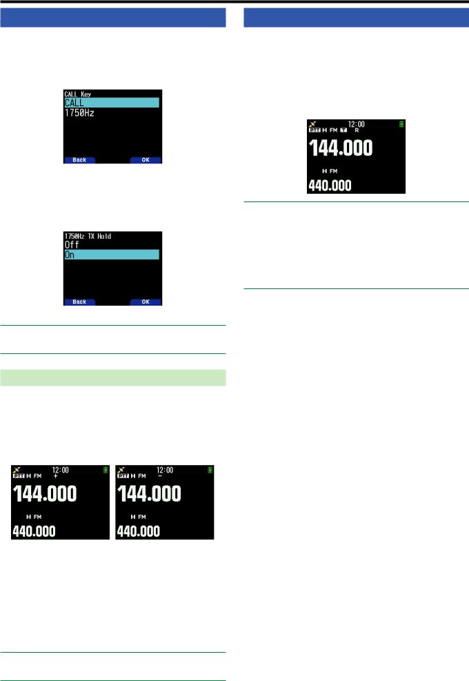
TRANSMITTING A 1750 Hz TONE
Most repeaters in Europe require that a transceiver transmit a 1750 Hz tone. On a TH-D74E, simply pressing [CALL] will transmit this tone. It is also possible to program [1750Hz] on the front panel as a [CALL] key for transmitting the 1750 Hz tone.
1 Access Menu No. 142.
2 Set to [1750Hz].
Some repeaters in Europe must receive continuous signals for a certain period of time, following a 1750 Hz tone. This transceiver is also capable of remaining in the transmit mode for 2 seconds after transmitting a 1750 Hz tone.
1 Access Menu No. 143.
2 Set to [On].
Note:
While remaining in the transmit mode, the transceiver does not continuously transmit a 1750 Hz tone.
Selecting an Offset Direction
The offset direction allows your transmit frequency to be higher (+) or lower (–) than the receive frequency.
1Select your desired band (A or B).
2Press [F], [REV] to select an offset direction.
•Each time you press [F], [REV], the offset direction changes as follows:
Simplex operation + – Simplex operation
•If you are using a TH-D74E, when operating on the 430
MHz band, the offset direction changes as follows:
Simplex operation + – = (–7.6 MHz) Simplex operation
If the offset transmit frequency falls outside the allowable range, transmitting is inhibited. Use one of the following methods to bring the transmit frequency within the band limits:
•Move the receive frequency further inside the band.
•Change the offset direction.
Note:
While using an odd-split memory channel or transmitting, you cannot change the offset direction.
REVERSE FUNCTION
After setting a separate receive and transmit frequency, you can exchange these frequencies using the Reverse function.
This allows you to manually check the strength of signals you receive directly from other stations, while using a repeater. If the station’s signal is strong, move to a simplex frequency to continue the contact and free up the repeater.
1Press [REV] to turn the Reverse function [On] or [Off].
•When the Reverse function is On, the <  > icon will appear on the display.
Note:
If the transmit frequency is outside the allowable transmit frequency range when using Reverse, pressing [PTT] will cause an error tone to sound and transmission will be inhibited.
If the receive frequency is outside the receive frequency range when using Reverse, an error tone will sound and Reverse will not operate.
The ARO (Automatic Repeater Offset) will not function when
Reverse is ON.
You cannot switch Reverse On or Off while transmitting.
7-3

 8 MEMORY CHANNEL
In Memory channels, you can store frequencies and related data that you often use. Then you need not reprogram
the data every time. You can quickly recall a programmed channel by simple operation. A total of 1101 Memory channels (1000 Memory channels, 100 Program scan memory, and Priority scan memory) are available.
SIMPLEX & REPEATER OR ODD-SPLIT MEMORY CHANNEL?
You can use each memory channel as a simplex & repeater channel or as an odd-split channel. Store only one frequency to use as a simplex & repeater channel or two separate frequencies to use as an odd-split channel. Select either application for each channel depending on the operations you have in mind.
Simplex & repeater channels allow:
•Simplex frequency operation
•Repeater operation with a standard offset (if an offset direction is stored)
Odd-split channels allow:
• Repeater operation with a non-standard offset
The data listed below can be stored in each Memory channel:
Parameter |
Simplex & |
Odd-split |
|
Repeater |
|||
|
|
||
|
|
|
|
Receive frequency |
Yes |
Yes |
|
|
|
||
Transmit frequency |
Yes |
||
|
|||
|
|
|
|
Receive frequency step size |
Yes |
Yes |
|
|
|
||
Transmit frequency step size |
Yes |
||
|
|||
|
|
|
|
Offset direction |
Yes |
No |
|
|
|
|
|
Tone On/Off |
Yes |
Yes |
|
|
|
|
|
Tone frequency |
Yes |
Yes |
|
|
|
|
|
CTCSS On/Off |
Yes |
Yes |
|
|
|
|
|
CTCSS frequency |
Yes |
Yes |
|
|
|
|
|
DCS On/Off |
Yes |
Yes |
|
|
|
|
|
DCS code |
Yes |
Yes |
|
|
|
|
|
Shift |
Yes |
No |
|
|
|
|
|
Reverse On/Off |
Yes |
No |
|
|
|
|
|
Memory channel lockout *2 |
Yes |
Yes |
|
Memory channel name |
Yes |
Yes |
|
|
|
|
|
Demodulation mode |
Yes |
Yes |
|
|
|
|
|
Cross tone |
Yes |
Yes |
|
|
|
|
|
Fine mode |
Yes |
Yes |
|
|
|
|
|
(Digital squelch) type * |
Yes |
No |
|
|
|
|
|
(Digital squelch) digital code * |
Yes |
No |
|
|
|
|
|
Destination Callsign * |
Yes |
No |
|
|
|
|
|
Access repeater Callsign * |
Yes |
No |
|
|
|
|
|
Destination repeater Callsign * |
Yes |
No |
|
|
|
|
|
|
|
|
Note:
Program scan memory and priority scan memory are excluded.
*: Data for the digital mode (DV/DR)
MEMORY CHANNEL LIST
The memory channel configurations can be displayed on the
Memory Channel List screen. In the Memory Channel List screen, you can select a channel to store or to recall.You can assign a name to a Memory Channel.
1Press [MR] to switch to the memory mode.
2Press [ENT].
Memory channel list appears.You can also access to the memory channel list by Menu No. 200.
Memory channel type
Display |
Type |
|
|
|
|
[0] to [999] |
Memory channels |
|
|
|
|
[L 0], [U 0] to [L49], [U49] |
Program scan memory |
|
|
|
|
[Pri] |
Priority scan memory |
|
|
|
|
[A 1] to [A10] |
Weather channels |
|
(TH-D74A only) |
||
|
||
|
|
|
[C] |
CALL channels |
|
|
|
3Select the channel.
You can select the channel by inputting the channel number from 0 to 999 by 12 keypad. When you select 1 or 2 digits channel, you can also select by inputting the channel number and pressing [ENT].
4Press [ENT].
The selected channel is set and return to the frequency display.
Switching Memory Name Display
The memory channel list display can be switched to frequency display or memory name.
1Press [A/B].
Each press switches between frequency display and memory name display.
8-1

Storing Simplex and Standard Repeater Frequencies
1Select the frequency, mode, etc.
2Press [F], [MR].
Memory channel registration screen appears on the display.
3Select the memory channel number.
4Press [ENT].
The simplex channel is registered.
Storing Odd-Split Repeater Frequencies
When you change the RX and TX frequencies, register the RX frequency first and then register the TX frequency. Only the TX frequency cannot be registered.
1Register the RX frequency.
A split channel can be registered only to an already registered memory channel.
2Display the TX frequency.
3Press [F], [MR].
Memory channel registration screen appears on the display.
4Select the memory channel number.
5Press [A/B].
The split channel is registered.
Note:
You cannot set the TX and RX frequencies on different frequency bands.
•Press [MODE] to return to the memory channel list menu.
5Press [A/B].
The specified memory channel is cleared.
To clear another memory channel, repeat the procedure from step 3.
RECALLING A MEMORY CHANNEL
You can recall a memory channel in the order of the channel number or select from a memory channel list.
Recalling in the order of memory channel number
1 Press [MR] to enter Memory Recall mode.
2 Press [ ]/[ ] or rotate the [ENC] control to select your desired Memory channel.
•Additionally, you can enter a channel number using the keypad.
Recalling from the memory channel list
1Press [MR] to enter Memory Recall mode.
Memory channels in the current frequency band or all memory channels will be recalled according to the setting in menu No. 202.
2Press [ENT].
The Memory channel list appears.
3 Press [ ]/[ ] or rotate the [ENC] control or enter a
3-digit channel number using the keypad.
The entered memory channel number will appear at the top of the list. When the memory channel number is two digits or less, press [ENT] after the number.
4Press [ENT].
The selected channel is configured and the screen returns to the frequency display.
Note:
When a split channel is recalled, “±” appears on the display.
A memory channel number cannot be recalled by keypad input if the memory channel is registered as program scan memory.
Clearing a Memory Channel
You can clear the specified channel of the registered memory channels.
1Press [MR] to enter the memory mode.
2Press [ENT].
The memory channel list appears.You can also access to the memory channel list by Menu No. 200.
3Select the specified channel and press [MENU]. The memory channel list menu appears.
4Select [Clear Memory] and press [A/B].
A confirmation message appears on the display.
8-2
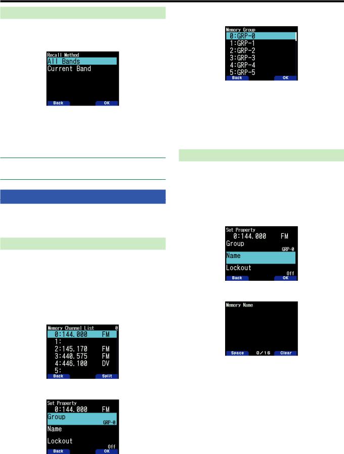
Memory Recall Method
This menu provides you with the option to recall memory channels with stored frequencies in your current frequency band, or all memory channels:
1 Access Menu No. 202.
2Select [All Bands] or [Current Band].
[All Bands]: This allows you to recall all programmed memory channels.
[Current Band]: This allows you to recall only those memory channels that have stored frequencies within the current frequency band.
Note:
This setting also applies to the memory scan and group link scan.
EDITING MEMORY CHANNEL
Setting the group in each memory channel, you can set registration of memory name and the lock-out for the memory scan.
3Select [Group] and press [A/B].
The memory group selection screen appears.
4Select any group from group 0 (GRP-0) to group 29 (GRP29) and press [A/B].
The selected group is set.
5Press [MODE] or [MENU].
Press [MODE] to return to the memory channel list. If you wish to set up another memory channel group, repeat from step 2. Press [MENU] to return to the frequency display.
Registering a Memory Name
You can assign a memory name of up to 16 characters to a memory channel. This is convenient because you can search with a callsign or place name for example, using a repeater.
1Display a memory channel list.
Press [ENT] in memory mode or call up the memory channel list from Menu No. 200.
2Select a channel and press [MODE]. The memory channel edit menu appears.
Setting Group
Each memory channel will be allocated to a group from group
0 to group 29. When a new memory channel is registered, It will be allocated to the group of the digit in the hundreds place. (CH.0 is group 0, Ch.100 is group 1, CH.200 is group 2, etc.) If a group is configured, memory channels for each group will be recalled and memory channel scan can be enabled for each group.
1Display a memory channel list.
Press [ENT] in memory mode or call up the memory channel list from Menu No. 200.
2Select a channel and press [MODE]. The memory channel edit menu appears.
3Select [Name] and press [A/B].
The memory name edit screen appears.
4Edit the name.
5Press [ENT].
The edited memory name is registered.
6Press [MODE] or [MENU].
Press [MODE] to return to the memory channel list. If you wish to register a memory name for another memory
channel, repeat from step 2. Press [MENU] to return to the frequency display.
8-3
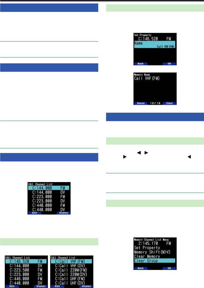
CALL CHANNEL MEMORY (SIMPLEX)
The CALL channel can be used to store any frequency and related data that you will recall often.You may want to
dedicate the CALL channel as an emergency channel within your group.
1Select the frequency, mode, etc.
2Press [F], [CALL].
Note:
Storing new data in the CALL channel will clear the old data.
(The CALL channel itself cannot be cleared, but data can be replaced with new data.)
CALL CHANNEL MEMORY (ODD-SPLIT)
The CALL channel can be used to store any frequency and related data that you will recall often.You may want to
dedicate the CALL channel as an emergency channel within your group.
1Register the RX frequency.
A split channel can be registered only to an already registered memory channel.
2Display the TX frequency.
4Press [F]
5Press [CALL] while pressing [PTT].
Note:
You cannot set the transmission and reception frequencies on different bands.
You cannot set a different frequency step size for the transmission and reception frequencies.
You cannot store the transmit offset status and Reverse status in an odd-split CALL channel.
CALL CHANNEL LIST
Select a CALL channel from the menu. The selected channel can also be edited.
1Access Menu No. 204.
The CALL channel list appears.
2Select a CALL channel.
3Press [ENT].
The CALL channel is accessed.
Switching Memory Name Display
Each press [A/B] switches between frequency and memory name display.
Editing a CALL Channel Name
You can name CALL channel using up to 8 characters.
1Access Menu No. 204.
2Select your desired CALL channel and press [MODE]. The Property menu appears.
3 Edit the CALL channel name.
MEMORY GROUP
You can divide the 1000 memory channels into a group of 30, and control them.
Switching Memory Group
1 |
Press [MR] to enter Memory Recall mode. |
|
|
2 |
Press |
] to select your desired Memory |
|
|
group |
]: increases Memory group number |
]: |
decrease Memory group number). The group name is displayed for about 2 seconds in memory name display area.
Note:
A Memory group in which memory channel has not been set is skipped.
You can switch the memory group to All Groups or each 30 group.
Clearing on a Memory Group Basis
Clear memory channels you no longer use on a memory group basis.
1Access Menu No. 200.
The memory channel list appears.
2Press [MENU].
The memory channel list menu appears.
8-4

3Select [Clear Group] and press [A/B]. The clear group selection screen appears.
The memory group name is registered and the frequency screen reappears.
4Select the group to clear.
5Press [ENT].
Each press adds or removes a check mark.
6Press [A/B].
The group clear confirmation screen appears.
•To end the operation without clearing the group, press
[MODE] to return to the previous screen.
7Press [A/B].
The specified group is cleared. If check marks are added to check boxes, multiple groups can be cleared simultaneously.
Memory Group Names
A name can be assigned to each of the 30 memory groups.
You can assign a group name of up to 16 half-width characters (or 8 full-width characters).
1Access Menu No. 201.
The name edit group selection screen appears.
2Select a group and press [A/B].
The group name input screen appears.
3Edit the group name.
4Press [ENT].
MEMORY SHIFT
Shift the contents of a memory channel or CALL channel to VFO.
Shifting Memory from the Frequency Screen
1Press [MR] or [CALL] to enter Memory Recall mode or
CALL channel mode.
2Recall your desired memory channel to shift to VFO. (This step is not necessary when selecting the CALL channel.)
3Press [F], [VFO].
The memory channel is copied to VFO.
•The entire contents of the Memory channel or CALL channel are copied to the VFO, and VFO mode is selected after the transfer is complete.
•When copying a transmit frequency from an odd-split Memory or CALL channel, you must first turn the
Reverse function on before pressing [F], [VFO].
Shifting Memory from the Memory Channel List
1Press [MR] to enter Memory Recall mode.
2Press [ENT].
The memory channel list screen appears.
3Select the memory channel to shift to VFO.
4Press [MENU].
The memory channel list menu appears.
5Select [Memory Shift (M>V)] and press [A/B].
The memory channel is copied to VFO and switches to VFO mode.
Shifting Memory from the CALL channel List
1Access Menu No. 204.
2Select a CALL channel.
3Press [MENU].
The CALL channel list menu appears.
4Select [Memory Shift (M>V)].
5Press [A/B].
The memory channel is copied to VFO.
8-5
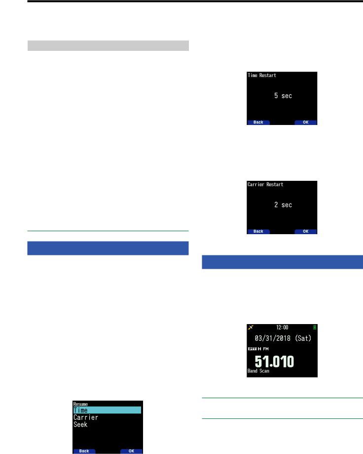
 9 SCAN
Scan is a useful feature for hands-off monitoring of your favorite frequencies. Becoming comfortable with all types of Scan will increase your operating efficiency.
This transceiver provides the following types of scans.
Scan Type |
Scan Range |
|
|
|
|
Band Scan |
Scans all frequencies on the current band. |
|
|
|
|
Memory Scan |
Scans all frequencies stored in the |
|
Memory channels. |
||
|
|
|
Group Link |
Scans memory channel in the plural |
|
memory groups registered in the group |
||
Scan |
||
link list.. |
||
|
||
|
|
|
Program Scan |
Scans all frequencies within the |
|
programmed range, on the current band. |
||
|
|
|
MHz Scan |
Scans all frequencies within a 1 MHz |
|
range from the originating frequency. |
||
|
||
|
|
|
|
Scans the Call channel as well as the |
|
Call Scan |
currently selected VFO frequency or |
|
|
Memory channel. |
|
|
|
|
Priority Scan |
Priority Scan checks the Priority Channel |
|
|
every 3 seconds. |
|
|
|
Note:
Adjust the squelch level before using scan. Selecting a squelch level too low could cause scan to stop immediately.
While using CTCSS or DCS, scan stops for any signal received; however, scan will immediately resume if the received signal does not contain the same CTCSS tone or DCS code that you selected.
Pressing and holding [PTT] causes scan to temporarily stop if it is functioning on a non TX band.
SELECTING A SCAN RESUME METHOD
The transceiver stops scanning at a frequency or Memory channel on which a signal is detected. It then continues scanning according to which resume mode you have selected. You can choose one of the following modes.
Time-Operated mode
Scan will stop temporarily once the squelch opens. Scan will resume 5 seconds later (default setting) regardless of the squelch status.
Carrier-Operated mode
Scan will stop temporarily once the squelch opens. Scan will resume if the squelch remains closed for more than 2 seconds (default setting).
Seek mode
Scan will complete once the squelch opens, and it will not resume.
1Access Menu No. 130.
• In digital (DV/DR mode), access Menu No. 131.
2Set the Scan Resume mode to [Time] (Time-Operated), [Carrier] (Carrier-Operated) or [Seek] (Seek).
Time-Operate Resume Time
Set the hold time for the Time-Operate scan method.
When a signal is received, scan will pause at that frequency for the duration of the hold time you set. When the set time elapses, scan will resume (even if the signal is still being received).
1Access Menu No. 132.
2Set the resume time to 1 ~ 10 sec.
Carrier-Operated Resume Time
Set the hold time for the Carrier-Operate scan method.
When a signal is received, scan will pause at that frequency. When the signal stops, scan will resume after the duration of the hold time you set.
1 Access Menu No. 133.
2 Set the resume time to 1 ~ 10 sec.
BAND SCAN
Band scan monitors all frequency range that is stored in
Menu No. 100 (Programmable VFO), using the current frequency step size.
1Select your desired operation band and frequency.
2Press [VFO] (1s).
Band scan appears and scan starts at the current frequency.
•The 1 MHz decimal point blinks while scanning is in progress.
Note:
When starting a scan within the frequency range of the registered program scan memory, it is the program scan.
3 To quit band scan, press [VFO].
9-1

PROGRAM SCAN
Program scan is to scan within the range between the lower limit frequency and upper limit frequency registered to program scan memory. There are 50 program scan memory from L0/U0 to L49/U49.
Setting Scan Limits
1Select the frequency, mode, etc. to register.
2Press [VFO].
3Press [F], [MR].
Memory channel registration screen appears on the display.
4To set a lower limit frequency, select channel [L0]. To set an upper limit frequency, select channel [U0].
5Press [ENT].
The frequency is registered in the memory channel. The picture below shows an example when a lower limit frequency is set in L0.
6Register the corresponding upper limit or lower limit frequency.
Repeat steps 3 to 6. Memory channels from L1/U1 to L49/ U49 can be registered similarly.
Using Program Scan
1Adjust the frequency within the range of the program scan memory.
•When the VFO frequency is within the registered frequency range in the program scan memory,
[Program No. 0] appears under the frequency display.
2Press [VFO] (1s).
The program scan starts and the dot of the 1 MHz digit flashes.
3To quit program scan, press [VFO].
Note:
When a frequency range registered in the program scan memory is duplicated, the range assigned to a smaller program scan memory number will be applied.
Band scan is activated if [VFO] is pressed for more than 1 second outside the program scan memory frequency range.
MHz SCAN
MHz scan monitors a 1 MHz segment of the band, using the current frequency step size. The current 1 MHz digit determines the limits of the scan. For example, if the current frequency is 145.400 MHz, then the scan range would be from 145.000 MHz to 145.995 MHz (the exact upper limit depends on the current frequency step size).
1Select your desired band.
2Press [VFO].
3 Press [ ]/[ ] or rotate the [ENC] control to select a frequency within your desired 1 MHz range.
4Press [MHz] (1s) to start scanning.
•Scan starts at the current frequency.
•The 1 MHz decimal point blinks while scanning is in progress.
•To reverse the scan direction, turn the [ENC]
control clockwise <or press [ ]> (upward scan) or counterclockwise <or press [
 ]> (downward scan).
5To quit MHz Scan, press [MHz].
MEMORY SCAN
Use memory scan to monitor all Memory channels programmed with frequency data.
1Press [MR] (1s).
Scan starts at the current memory channel.
2 To quit memory scan, press [MR].
Note:
At least 2 Memory channels must contain data and must not be locked out of scan.
Program scan memory and priority channel will be excluded from the memory scan.
If the memory recall method is set to [Current Band], the memory channel of the same frequency band as the current memory channel will be scanned. The other memory channel will be skipped.
9-2
Loading...