


INSTRUCTION MANUAL
VHF FM TRANSCEIVER
TK-780
UHF FM TRANSCEIVER
TK-880
800 MHz FM TRANSCEIVER
TK-980
© B62-1322-30 (M) 09 08 07 06 05 04 03

THANK YOU!
We are grateful you chose KENWOOD for your personal mobile applications. We believe this easy-to-use transceiver will provide dependable communications to keep personnel operating at peak efficiency.
KENWOOD transceivers incorporate the latest in advanced technology. As a result, we feel strongly that you will be pleased with the quality and features of this product.
PRECAUTIONS
Please observe the following precautions to prevent fire, personal injury, and transceiver damage.
•Do not attempt to configure the transceiver while driving; it is too dangerous.
•Do not modify the transceiver for any reason.
•Do not expose the transceiver to long periods of direct sunlight, nor place it near heating appliances.
•Do not place the transceiver in excessively dusty, humid, or wet areas, not on unstable surfaces.
•If an abnormal odor or smoke is detected coming from the transceiver, turn OFF the power immediately. Contact your KENWOOD dealer.
NOTICES TO THE USER
GOVERNMENT LAW PROHIBITS THE OPERATION OF UNLICENSED RADIO TRANSMITTERS WITHIN THE TERRITORIES UNDER GOVERNMENT CONTROL.
ILLEGAL OPERATION IS PUNISHABLE BY FINE OR IMPRISONMENT OR BOTH.
REFER SERVICE TO QUALIFIED TECHNICIANS ONLY.
SAFETY: It is important that the operator is aware of, and understands, hazards common to the operation of any transceiver.
WARNING!
EXPLOSIVE ATMOSPHERES (GASES, DUST, FUMES, etc.)
Turn OFF your transceiver while taking on fuel or while parked in gasoline service stations. Do not carry spare fuel containers in the trunk of your vehicle if your transceiver is mounted in the trunk area.
INJURY FROM RADIO FREQUENCY TRANSMISSIONS
Do not operate your transceiver when somebody is either touching the antenna or standing within two to three feet of it, to avoid the possibility of radio frequency burns or related physical injury.
DYNAMITE BLASTING CAPS
Operating the transceiver within 500 feet of dynamite blasting caps may cause them to explode.
Turn OFF your transceiver when in an area where blasting is in progress, or where “TURN OFF
TWO-WAY RADIO” signs have been posted. If you are transporting blasting caps in your vehicle, make sure they are carried in a closed metal box with a padded interior. Do not transmit while the caps are being placed into or removed from the container.

CONTENTS
UNPACKING AND CHECKING EQUIPMENT ................................... |
1 |
SUPPLIED ACCESSORIES .......................................................... |
1 |
PREPARATION .................................................................................. |
2 |
TOOLS REQUIRED ...................................................................... |
2 |
POWER CABLE CONNECTION .................................................. |
2 |
INSTALLING THE TRANSCEIVER .............................................. |
3 |
ORIENTATION .................................................................................... |
4 |
FRONT PANEL AND MICROPHONE ........................................... |
4 |
DISPLAY ........................................................................................ |
5 |
REAR PANEL ................................................................................ |
5 |
PROGRAMMABLE AUXILIARY FUNCTIONS .................................. |
6 |
BASIC OPERATIONS ........................................................................ |
8 |
OPERATION OVERVIEW ............................................................. |
8 |
Trunking Format ..................................................................... |
8 |
Conventional Format (TK-780 and TK-880 only) ................. |
8 |
SWITCHING POWER ON/OFF ..................................................... |
8 |
ADJUSTING THE VOLUME ......................................................... |
8 |
SELECTING A SYSTEM/ GROUP/ CHANNEL ............................ |
8 |
TIME-OUT TIMER (TOT)............................................................... |
8 |
HORN ALERT ............................................................................... |
8 |
TRUNKING FORMAT ......................................................................... |
9 |
TRUNKED OPERATION ............................................................... |
9 |
Placing a Dispatch Call .......................................................... |
9 |
Receiving a Dispatch Call ...................................................... |
9 |
Placing a Telephone Call ....................................................... |
9 |
Receiving a Telephone Call ................................................. |
10 |
CONVENTIONAL OPERATION .................................................. |
10 |
Transmitting .......................................................................... |
10 |
Receiving ............................................................................... |
10 |
SYSTEM SCAN ........................................................................... |
10 |
Scanning Trunked Systems.................................................. |
11 |
Scanning Conventional Systems ......................................... |
11 |
Scan Lockout ......................................................................... |
11 |
Scan Revert ............................................................................ |
11 |
GROUP SCAN.............................................................................. |
11 |
i

CONVENTIONAL FORMAT (TK-780 and TK-880 only) ................ |
12 |
CONVENTIONAL OPERATION .................................................. |
12 |
Transmitting .......................................................................... |
12 |
Receiving ............................................................................... |
12 |
SCAN ........................................................................................... |
13 |
Priority Scan.......................................................................... |
13 |
2-TONE SIGNALLING ................................................................ |
13 |
FleetSync: ALPHANUMERIC TWO-WAY PAGING FUNCTION ... |
14 |
KEY FUNCTIONS ....................................................................... |
14 |
SHORT MESSAGES FEATURE ................................................. |
14 |
GPS REPORT ............................................................................. |
14 |
SELCALL (SELECTIVE CALLING) ............................................ |
15 |
Transmitting .......................................................................... |
15 |
Receiving ............................................................................... |
15 |
Identification Codes ............................................................. |
15 |
STATUS MESSAGE .................................................................... |
15 |
Transmitting .......................................................................... |
16 |
Receiving ............................................................................... |
16 |
Reviewing Messages in the Stack Memory ....................... |
16 |
Automatic Status Response ................................................ |
16 |
DTMF (DUAL TONE MULTI FREQUENCY) CALLS ....................... |
17 |
MAKING A DTMF CALL ............................................................. |
17 |
DTMF SIGNALLING .................................................................... |
18 |
DBD (DEAD BEAT DISABLE) .................................................... |
18 |
AUDIBLE USER FEEDBACK TONES ............................................ |
19 |
ii

UNPACKING AND CHECKING EQUIPMENT
Note: The following unpacking instructions are for use by your KENWOOD dealer, an authorized KENWOOD service facility, or the factory.
Carefully unpack the transceiver. We recommend that you identify the items listed in the following table before discarding the packing material. If any items are missing or have been damaged during shipment, file a claim with the carrier immediately.
SUPPLIED ACCESSORIES
Item |
Quantity |
|
Microphone and microphone cable (TK-980 only) |
1 |
|
|
|
|
Microphone hanger with self-tapping screws |
1 set |
|
(TK-980 only) |
||
|
||
|
|
|
DC power cable kit |
1 set |
|
• Fuse (10 A) |
||
|
||
|
|
|
Mounting bracket |
1 |
|
|
|
|
Speaker jack cap |
1 |
|
|
|
|
Screw set: |
|
|
• Self-tapping screw (4 pieces) |
|
|
• Hex-headed screw with washer (4 pieces) |
1 set |
|
• Spring washer (4 pieces) |
|
|
• Flat washer (4 pieces) |
|
|
|
|
|
Instruction manual |
1 |
|
|
|
Microphone and |
Microphone hanger |
DC power cable kit |
microphone cable |
with self-tapping screws |
|
(TK-980 only) |
(TK-980 only) |
|
Mounting bracket |
Speaker jack cap |
Screw set |
1

PREPARATION
VARIOUS ELECTRONIC EQUIPMENT IN YOUR VEHICLE MAY MALFUNCTION IF THEY ARE NOT PROPERLY PROTECTED FROM THE RADIO FREQUENCY ENERGY WHICH IS PRESENT WHILE TRANSMITTING. ELECTRONIC FUEL INJECTION, ANTI-SKID BRAKING, AND CRUISE CONTROL SYSTEMS ARE TYPICAL EXAMPLES OF EQUIPMENT THAT MAY MALFUNCTION. IF YOUR VEHICLE CONTAINS SUCH EQUIPMENT, CONSULT THE DEALER FOR THE MAKE OF VEHICLE AND ENLIST HIS AID IN DETERMINING IF THEY WILL PERFORM NORMALLY WHILE TRANSMITTING.
Note: The following preparation instructions are for use by your KENWOOD dealer, an authorized
KENWOOD service facility, or the factory.
TOOLS REQUIRED
Note: Before installing the transceiver, always check how far the mounting screws will extend below the mounting surface. When drilling mounting holes, be careful not to damage vehicle wiring or parts.
The following tools are required for installing the transceiver:
•6 mm (1/4 inch) or larger electric drill
•Drill bits (sizes listed below) and circle cutters
Drill Bit Size |
Purpose |
4.2 mm (5/32 inch) |
5 x 16 mm self-tapping screws |
|
|
3.2 mm (1/8 inch) |
4 x 16 mm self-tapping screws |
|
|
POWER CABLE CONNECTION
THE TRANSCEIVER OPERATES IN 12 V NEGATIVE GROUND SYSTEMS ONLY! CHECK THE BATTERY POLARITY AND VOLTAGE OF THE VEHICLE BEFORE INSTALLING THE
TRANSCEIVER.
1Check for an existing hole, conveniently located in the firewall, where the power cable can be passed through.
•If no hole exists, use a circle cutter to drill the firewall, then install a rubber grommet.
2Run the two power cable leads through the firewall and into the engine compartment, from the passenger compartment.
3Connect the red lead to the positive (+) battery terminal and the black lead to the negative (–) battery terminal.
•Locate the fuse as close to the battery as possible.
4Recoil and secure the surplus cable with the provided retaining band.
•Be sure to leave enough slack in the cables so the transceiver can be removed for servicing while keeping the power applied.
2
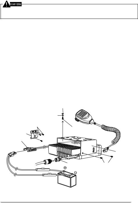
INSTALLING THE TRANSCEIVER
FOR PASSENGER SAFETY, INSTALL THE TRANSCEIVER SECURELY, USING THE SUPPLIED MOUNTING BRACKET, SO THE TRANSCEIVER WILL NOT BREAK LOOSE IN THE EVENT OF A COLLISION.
1Mark the position of the holes in the dash by using the mounting bracket as a template. Drill the holes, then attach the mounting bracket using the supplied 5 x 16 mm screws.
•Be sure to mount the transceiver in a location where the controls are within easy reach of the user, and where there is sufficient space at the rear of the transceiver for cable connections.
2Connect the antenna and the supplied power cable to the transceiver.
3Slide the transceiver into the mounting bracket and secure it using the supplied hex-headed screws.
4Mount the microphone hanger, using the supplied 4 x 16 mm screws, in a location where it will be within easy reach of the user.
•The microphone and microphone cable should be mounted in a place where they will not interfere with the safe operation of the vehicle.
TK-980 only: Connect one plug of the microphone cable to the jack on the base of the microphone, and the other plug to the microphone jack on the front panel of the transceiver. Place the microphone on the hanger.
Flat washer
Spring washer
4 x 16 mm self-tapping screw (TK-980 only)
Microphone hanger (TK-980 only)
Power input connector
Microphone and microphone cable (TK-980 only)
5 x 16 mm self-tapping screw
Mounting bracket
Antenna |
Hex-headed screw |
connector |
DC power cable |
12 V vehicle |
|
battery |
||
|
* The above diagram shows the TK-780/ TK-880 transceiver. The antenna connector of the TK-980 transceiver is different.
3

ORIENTATION
FRONT PANEL AND MICROPHONE
q w |
e |
r |
|
|
|
|
|
|
|
|
|
|
|
|
|
|
|
|
|
|
|
|
|
|
|
|
|
|
|
|
|
|
t |
|
|
y |
u * The microphone comes only |
|||||
|
|
|
|
|
|
|
|
|
with the TK-980 transceiver. |
qIO (Power) switch
Press to switch the transceiver ON (or OFF).
w  /
/ keys
keys
Press these keys to activate their programmable auxiliary functions {page 6}.
eDisplay
See page 5 for more information.
r  /
/ keys
keys
Press these keys to activate their programmable auxiliary functions {page 6}.
tMicrophone jack
Insert the microphone plug into this connector.
yMON, A, B, pC, Do, and SCN keys
Press these keys to activate their programmable auxiliary functions {page 6}.
uPTT switch
To transmit, press and hold this switch, then speak into the microphone. Release to receive.
4
DISPLAY
|
|
|
|
|
|
|
|
|
|
|
|
|
|
|
|
|
|
|
|
|
|
|
|
|
|
|
|
|
|
|
|
|
|
|
|
|
|
|
|
|
|
|
|
|
|
|
|
|
|
|
|
|
|
|
|
|
|
|
|
|
|
|
|
|
|
|
|
|
|
|
|
|
|
|
|
|
|
|
|
|
|
|
|
|
|
|
|
|
|
|
|
|
|
|
|
|
|
|
|
|
|
|
|
|
|
|
|
|
|
|
|
|
|
|
|
|
|
|
|
|
|
|
|
|
|
|
|
|
|
|
|
|
|
|
|
|
|
|
|
|
|
|
|
|
|
|
|
|
|
|
|
|
|
|
|
|
|
|
|
|
|
|
|
|
|
|
|
|
|
|
|
|
|
|
|
|
|
|
|
|
|
|
|
|
|
|
|
|
|
|
|
|
|
|
|
|
|
|
|
|
|
|
|
|
|
|
|
|
|
|
|
|
|
|
|
|
|
|
|
|
|
|
|
|
|
|
|
|
|
|
|
|
|
|
|
|
|
|
|
|
|
|
|
|
|
|
|
|
|
|
|
|
|
|
|
|
|
|
|
|
Indicator |
|
|
|
|
|
|
|
|
|
|
|
|
Description |
|||||||||||||||||||||||||||||||||||||||||||||
|
|
|
|
|
|
|
|
|
|
|
|
|
|
|
|
|
|
|
|
Displays the system, group, and channel numbers. Also displays |
|||||||||||||||||||||||||||||||||||||||||||
|
|
|
|
|
|
|
|
|
|
|
|
|
|
|
|
|
|
|
|
||||||||||||||||||||||||||||||||||||||||||||
|
|
|
|
|
|
|
|
|
|
|
|
|
|
|
|
|
|
|
|
various functions which have been programmed by your dealer. |
|||||||||||||||||||||||||||||||||||||||||||
|
|
|
|
|
|
|
|
|
|
|
|
|
|
|
|
|
|
|
|
||||||||||||||||||||||||||||||||||||||||||||
|
|
|
|
|
|
|
|
|
|
|
|
|
|
|
|
|
|
|
|
Appears when the selected channel is programmed as priority. |
|||||||||||||||||||||||||||||||||||||||||||
|
|
|
|
|
|
|
|
|
|
|
|
|
|
|
|
|
|
|
|
|
|
|
|
|
|
|
|
|
|
|
|
|
|
|
|
|
|
|
|
|
|
|
|
|
|
|
|
|
|
|
|
|
|
|
|
|
|
|
|
|
|
|
|
|
|
|
|
|
|
|
|
|
|
|
|
|
|
|
|
|
|
|
|
Appears when the key programmed as Monitor is pressed. |
|||||||||||||||||||||||||||||||||||||||||||
|
|
|
|
|
|
|
|
|
|
|
|
|
|
|
|
|
|
|
|
|
|
|
|
|
|
|
|
|
|
|
|
|
|
|
|
|
|
|
|
|
|
|
|
|
|
|
|
|
|
|
|
|
|
|
|
|
|
|
|
|
|
|
|
|
|
|
|
|
|
|
|
|
|
|
|
|
|
|
|
|
|
|
|
This icon is not used on this transceiver. |
|||||||||||||||||||||||||||||||||||||||||||
|
|
|
|
|
|
|
|
|
|
|
|
|
|
|
|
|
|
|
|
|
|
|
|
|
|
|
|
|
|
|
|
|
|
|
|
|
|
|
|
|
|
|
|
|
|
|
|
|
|
|
|
|
|
|
|
|
|
|
|
|
|
|
|
|
|
|
|
|
|
|
|
|
|
|
|
|
|
|
|
|
|
|
|
Appears when you are using Scan mode. |
|||||||||||||||||||||||||||||||||||||||||||
|
|
|
|
|
|
|
|
|
|
|
|
|
|
|
|
|
|
|
|
|
|
|
|
|
|
|
|
|
|
|
|
|
|
|
|
|
|
|
|
|
|
|
|
|
|
|
|
|
|
|
|
|
|
|
|
|
|
|
|
|
|
|
|
|
|
|
|
|
|
|
|
|
|
|
|
|
|
|
|
|
|
|
|
Appears when the auxiliary function is activated. |
|||||||||||||||||||||||||||||||||||||||||||
|
|
|
|
|
|
|
|
|
|
|
|
|
|
|
|
|
|
|
|
|
|
|
|
|
|
|
|
|
|
|
|
|
|
|
|
|
|
|
|
|
|
|
|
|
|
|
|
|
|
|
|
|
|
|
|
|
|
|
|
|
|
|
|
|
|
|
|
|
|
|
|
|
|
|
|
|
|
|
|
|
|
|
|
In Trunking Format, appears when the selected group is |
|||||||||||||||||||||||||||||||||||||||||||
|
|
|
|
|
|
|
|
|
|
|
|
|
|
|
|
|
|
|
|
programmed as telephone IDs. In Conventional Format, appears |
|||||||||||||||||||||||||||||||||||||||||||
|
|
|
|
|
|
|
|
|
|
|
|
|
|
|
|
|
|
|
|
when you are using the Operator Selectable Tone function. |
|||||||||||||||||||||||||||||||||||||||||||
|
|
|
|
|
|
|
|
|
|
|
|
|
|
|
|
|
|
|
|
|
|
|
|
|
|
|
|
|
|
|
|
|
|
|
|
|
|
|
|
|
|
|
|
|
|
|
|
|
|
|
|
|
|
|
|
|
|
|
|
|
|
|
|
|
|
|
|
|
|
|
|
|
|
|
|
|
|
|
|
|
|
|
|
Flashes when you receive a message. Lights when a message is |
|||||||||||||||||||||||||||||||||||||||||||
|
|
|
|
|
|
|
|
|
|
|
|
|
|
|
|
|
|
|
|
stored in the stack memory. |
|||||||||||||||||||||||||||||||||||||||||||
|
|
|
|
|
|
|
|
|
|
|
|
|
|
|
|
|
|
|
|
|
|
|
|
|
|
|
|
|
|
|
|
|
|
|
|
|
|
|
|
|
|
|
|
|
|
|
|
|
|
|
|
|
|
|
|
|
|
|
|
|
|
|
|
|
|
|
|
|
|
|
|
|
|
|
|
|
|
|
|
|
|
|
|
Displays the system, group, and channel numbers. Your dealer |
|||||||||||||||||||||||||||||||||||||||||||
|
|
|
|
|
|
|
|
|
|
|
|
|
|
|
|
|
|
|
|
can program the system, group, and channel names with up to 10 |
|||||||||||||||||||||||||||||||||||||||||||
|
|
|
|
|
|
|
|
|
|
|
|
|
|
|
|
|
|
|
|
characters, in place of numbers. The left most display is used as a |
|||||||||||||||||||||||||||||||||||||||||||
|
|
|
|
|
|
|
|
|
|
|
|
|
|
|
|
|
|
|
|
delete indicator ( |
) in Trunking Format and an add indicator ( ) in |
||||||||||||||||||||||||||||||||||||||||||
|
|
|
|
|
|
|
|
|
|
|
|
|
|
|
|
|
|
|
|
Conventional Format. The right most display is used for the |
|||||||||||||||||||||||||||||||||||||||||||
|
|
|
|
|
|
|
|
|
|
|
|
|
|
|
|
|
|
|
|
||||||||||||||||||||||||||||||||||||||||||||
|
|
|
|
|
|
|
|
|
|
|
|
|
|
|
|
|
|
|
|
Selective Call ( |
) or Scrambler ( _ ) function. The delete/ add |
||||||||||||||||||||||||||||||||||||||||||
|
|
|
|
|
|
|
|
|
|
|
|
|
|
|
|
|
|
|
|
indicators show the systems/ channels that are locked/ not locked |
|||||||||||||||||||||||||||||||||||||||||||
|
|
|
|
|
|
|
|
|
|
|
|
|
|
|
|
|
|
|
|
out of the scanning sequence. Selective Call and Scrambler are |
|||||||||||||||||||||||||||||||||||||||||||
|
|
|
|
|
|
|
|
|
|
|
|
|
|
|
|
|
|
|
|
optional functions that can be programmed by your dealer. Also |
|||||||||||||||||||||||||||||||||||||||||||
|
|
|
|
|
|
|
|
|
|
|
|
|
|
|
|
|
|
|
|
displays received messages when using DMS. |
|||||||||||||||||||||||||||||||||||||||||||
REAR PANEL |
|
|
|
|
|
|
|
|
|
|
|
|
|
|
|
|
|
|
|
|
|
|
|
|
|
|
|
|
|
|
|
|
|
|
|
|
|||||||||||||||||||||||||||
|
|
|
|
|
|
|
|
|
|
|
|
|
|
|
|
|
|
|
|
|
|
|
|
|
|
|
|
|
|
|
|
|
|
|
|
|
|
|
|
|
|
|
|
|
|
|
|
|
|
|
|
|
|
|
|
|
|
|
|
|
|
|
|
|
|
|
|
|
|
|
|
|
|
|
|
|
|
|
|
|
|
|
|
|
|
|
|
|
|
|
|
|
|
|
|
|
|
|
|
|
|
|
|
|
|
|
|
|
|
|
|
|
|
|
|
|
|
|
|
|
|
|
|
|
|
|
|
|
|
|
|
|
|
|
|
|
|
|
|
|
|
|
|
|
|
|
|
|
|
|
|
|
|
|
|
|
|
|
|
|
|
|
|
|
|
|
|
|
|
|
|
|
|
|
|
|
|
|
|
|
|
|
|
|
|
|
|
|
|
|
|
|
|
|
|
|
|
|
|
|
|
|
|
|
|
|
|
|
|
|
|
|
|
|
|
|
|
|
|
|
|
|
|
|
|
|
|
|
|
|
|
|
|
|
|
|
|
|
|
|
|
|
|
|
|
|
|
|
|
|
|
|
|
|
|
|
|
|
|
|
|
|
|
|
|
|
|
|
|
|
|
|
|
|
|
|
|
|
|
|
|
|
|
|
|
|
|
|
|
|
|
|
|
|
|
|
|
|
|
|
|
|
|
|
|
|
|
|
|
|
|
|
|
|
|
|
|
|
|
|
|
|
|
|
|
|
|
|
|
|
|
|
|
|
|
|
|
|
|
|
|
|
|
|
|
|
|
|
|
|
|
|
|
|
|
|
|
|
|
|
|
|
|
|
|
|
|
|
|
|
|
|
|
|
|
|
|
|
|
|
|
|
|
|
|
|
|
|
|
|
|
|
|
|
|
|
|
|
|
|
|
|
|
|
|
|
|
|
|
|
|
|
|
|
|
|
|
|
|
|
|
|
|
|
|
|
|
|
|
|
|
|
|
|
|
|
|
|
|
|
|
|
|
|
|
|
|
|
|
|
|
|
|
|
|
|
|
|
|
|
|
|
|
|
|
|
|
|
|
|
|
|
|
|
|
|
|
|
|
|
|
|
|
|
|
|
|
|
|
|
|
|
|
|
|
|
|
|
|
|
|
|
|
|
|
|
|
|
|
|
|
|
|
|
|
|
|
|
|
|
|
|
|
|
|
|
|
|
|
|
|
|
|
|
|
|
|
|
|
|
|
|
|
|
|
|
|
|
|
|
|
|
|
|
|
|
|
|
|
|
|
|
|
|
|
|
|
|
|
|
|
|
|
|
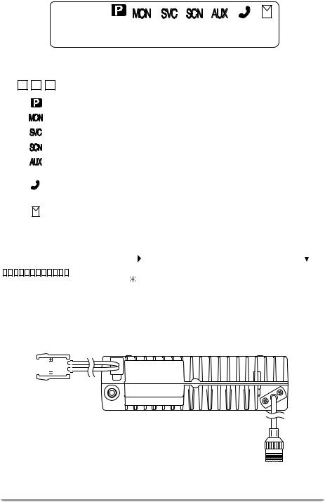
|
Power input |
External |
connector |
speaker jack |
Antenna connector
* The above diagram shows the TK-780/ TK-880 transceiver. The antenna connector of the TK-980 transceiver is different.
5

PROGRAMMABLE AUXILIARY FUNCTIONS
Keys w, r, and y {page 4} can be programmed with the auxiliary functions listed in the following table. The keys can only be programmed with functions, depending on whether you are using Conventional Format or Trunking Format. Please contact your dealer for further details on these functions.
Note:
If “Function” is programmed onto one of the above mentioned keys, the microphone keypad can also be used for additional programmable keys.
Only the TK-780 and TK-880 transceivers support Conventional Format.
Function |
Conventional |
Trunking |
|
Format |
Format |
||
|
|||
Auto Tel |
No |
Yes |
|
|
|
|
|
AUX A |
Yes |
Yes |
|
|
|
|
|
AUX B 1 |
Yes |
Yes |
|
Channel Down |
Yes |
No |
|
|
|
|
|
Channel Up |
Yes |
No |
|
|
|
|
|
Display Character |
Yes |
Yes |
|
|
|
|
|
DTMF ID (BOT) |
Yes |
Yes |
|
|
|
|
|
DTMF ID (EOT) |
Yes |
Yes |
|
|
|
|
|
Function |
Yes |
Yes |
|
|
|
|
|
Group Down |
Yes |
Yes |
|
|
|
|
|
Group Up |
Yes |
Yes |
|
|
|
|
|
Home Channel |
Yes |
No |
|
|
|
|
|
Home Group |
No |
Yes |
|
|
|
|
|
Horn Alert |
Yes |
Yes |
|
|
|
|
|
Key Lock |
Yes |
Yes |
|
|
|
|
|
Memory (RCL/STO) |
Yes |
Yes |
|
|
|
|
|
Memory (RCL) |
Yes |
Yes |
|
|
|
|
|
Memory (STO) |
Yes |
Yes |
|
|
|
|
|
Message Mode |
Yes |
Yes |
|
|
|
|
|
Monitor A (Monitor Unmute (Momentary)) |
Yes |
Yes |
|
|
|
|
|
Monitor B (Monitor Unmute (Toggle)) |
Yes |
Yes |
|
|
|
|
|
Monitor C (Carrier Squelch (Momentary)) |
Yes |
Yes |
|
|
|
|
|
Monitor D (Carrier Squelch (Toggle)) |
Yes |
Yes |
|
|
|
|
|
Operator Sel Tone |
Yes |
No |
|
|
|
|
|
Public Address |
Yes |
Yes |
|
|
|
|
6
Function |
Conventional |
Trunking |
|
Format |
Format |
||
|
|||
Redial |
Yes |
Yes |
|
|
|
|
|
Scan |
Yes |
Yes |
|
|
|
|
|
Scan Del/Add |
Yes |
Yes |
|
|
|
|
|
Scan Temporary Delete |
No |
Yes |
|
|
|
|
|
Scrambler 2 |
Yes |
Yes |
|
Send GPS 3 |
Yes |
Yes |
|
System Down |
No |
Yes |
|
|
|
|
|
System Up |
No |
Yes |
|
|
|
|
|
Talk Around |
Yes |
No |
|
|
|
|
|
Tel Disconnect |
No |
Yes |
|
|
|
|
|
Volume Down |
Yes |
Yes |
|
|
|
|
|
Volume Up |
Yes |
Yes |
|
|
|
|
1This function can be selected only when the Scrambler/ ANI board has not been installed.
2This function can be selected only when the Scrambler board has been installed.
3This function can be selected only when a GPS receiver has been installed.
The Emergency function can also be programmed. However, it can only be used with a foot switch.
7

BASIC OPERATIONS
OPERATION OVERVIEW
■Trunking Format
This format can handle up to 600 channels in conventional mode, and 32 systems with up to 250 groups in each system in trunking mode. Systems, groups, channels, and their functions are programmed by your dealer.
■Conventional Format (TK-780 and TK-880 only)
This format can handle up to 250 groups with 250 channels in each group. The transceiver can be used only in conventional mode. Groups, channels, and their functions are programmed by your dealer.
SWITCHING POWER ON/OFF
Press the IO switch to switch the transceiver ON (or OFF).
ADJUSTING THE VOLUME
Press the keys programmed as Volume Up and Volume Down to adjust the volume. Volume Up increases the volume and Volume Down decreases it.
SELECTING A SYSTEM/ GROUP/ CHANNEL
Select the desired system and group (Trunking Format) using the keys programmed with the System and Group functions.
Select the desired group and channel (Conventional Format) using the keys programmed with the Group and Channel functions.
TIME-OUT TIMER (TOT)
The purpose of the Time-out Timer is to prevent any caller from using a channel for an extended period of time.
If you continuously transmit for a period of time that exceeds the programmed time, the transceiver will stop transmitting and an alert tone will sound. To stop the tone, release the PTT switch.
Your dealer can program the TOT time in the range of 15 seconds to 10 minutes.
HORN ALERT
If Horn Alert has been installed by your dealer, your vehicle horn, or some other type of external alert, will sound when certain calls are received. This is a useful function when you are away from your vehicle.
8

TRUNKING FORMAT
TRUNKED OPERATION
■Placing a Dispatch Call
1 Select the desired system and group using the System and Group keys.
2 Press the PTT switch.
3 If a tone does not sound, communication is possible; start speaking into the microphone. Release the PTT switch to receive.
•For best sound quality at the receiving station, hold the microphone approximately 1.5 inches (3 ~ 4 cm) from your mouth.
4When your conversation is finished, return the microphone to its hanger.
■Receiving a Dispatch Call
1Select the desired system and group using the System and Group keys. (If the Scan function has been programmed, you can switch it ON or OFF as desired.)
2When you hear the dispatcher’s voice, readjust the volume as necessary.
■Placing a Telephone Call
Note: You can make a telephone call only if the telephone service is available and you have an optional keypad microphone. Refer to “MAKING A DTMF CALL” on page 17. Consult your dealer for further details.
1Select the desired system and group using the System and Group keys.
2Press and hold the PTT switch for approximately 1 second to ensure a connection.
•Confirm that there is a dial tone after releasing the PTT switch.
3Dial using the microphone keypad.
•After dialing, wait for a response from the called party.
4When the called party responds, press the PTT switch and speak into the microphone. Release the PTT switch to receive.
•Only one person can speak at a time.
5To end the call, press the # key or the key programmed as Tel Disconnect.
9

■Receiving a Telephone Call
1Select the desired system and group using the System and Group keys. (If the Scan function has been programmed, you can switch it ON or OFF as desired.)
•A ringing tone will sound when a call is received.
2Press and hold the PTT switch to speak, and release it to listen.
•Only one person can speak at a time.
3To end the call, press the # key or the key programmed as Tel Disconnect.
CONVENTIONAL OPERATION
■ Transmitting
Note: Before transmitting, monitor the channel to make sure it is not already in use. If the selected group is programmed with QT (Quiet Talk) or DQT (Digital Quiet Talk), remove the microphone from the hook to disable QT or DQT, then listen to the channel to make sure nobody is talking on it. If the selected group is not programmed with QT or DQT, simply listen to the channel to make sure nobody is talking on it. In this case, you need not remove the microphone from the hook.
1Select the desired system and group using the System and Group keys.
•If the channel is busy, wait until it becomes free.
2Press the PTT switch and speak into the microphone. Release the PTT switch to receive.
•For best sound quality at the receiving station, hold the microphone approximately 1.5 inches (3 ~ 4 cm) from your mouth.
3When your conversation is finished, return the microphone to its hanger.
■Receiving
1Select the desired system and group using the System and Group keys. (If the Scan function has been programmed, you can switch it ON or OFF as desired.)
2When you hear the dispatcher’s voice, readjust the volume as necessary.
SYSTEM SCAN
If the Scan function is programmed, systems can be scanned by pressing the key programmed as Scan. When the Scan key is pressed, the SCN indicator and “-SCAN-” or the revert system/ group number, appear on the display and scanning starts. The systems not locked out of the scanning sequence are scanned.
When a call is received, scanning stops and the system and group digits appear. Press the PTT switch and speak into the microphone to respond to the call. The transceiver will continue scanning after an adjustable time delay if the PTT switch is released and no further signal is received.
10
 Loading...